EP0012702A1 - Procédé et dispositif pour emboutissage hydromécanique - Google Patents
Procédé et dispositif pour emboutissage hydromécanique Download PDFInfo
- Publication number
- EP0012702A1 EP0012702A1 EP79420066A EP79420066A EP0012702A1 EP 0012702 A1 EP0012702 A1 EP 0012702A1 EP 79420066 A EP79420066 A EP 79420066A EP 79420066 A EP79420066 A EP 79420066A EP 0012702 A1 EP0012702 A1 EP 0012702A1
- Authority
- EP
- European Patent Office
- Prior art keywords
- ring
- blank
- liquid
- stamping
- punch
- Prior art date
- Legal status (The legal status is an assumption and is not a legal conclusion. Google has not performed a legal analysis and makes no representation as to the accuracy of the status listed.)
- Withdrawn
Links
- 238000000034 method Methods 0.000 title claims abstract description 21
- 239000007788 liquid Substances 0.000 claims abstract description 51
- 239000011159 matrix material Substances 0.000 claims abstract description 15
- 238000004891 communication Methods 0.000 claims description 4
- 238000004519 manufacturing process Methods 0.000 abstract description 4
- 229910052751 metal Inorganic materials 0.000 description 4
- 239000002184 metal Substances 0.000 description 4
- 238000005461 lubrication Methods 0.000 description 2
- XLYOFNOQVPJJNP-UHFFFAOYSA-N water Substances O XLYOFNOQVPJJNP-UHFFFAOYSA-N 0.000 description 2
- 229910000838 Al alloy Inorganic materials 0.000 description 1
- 230000015572 biosynthetic process Effects 0.000 description 1
- 238000007796 conventional method Methods 0.000 description 1
- 230000002950 deficient Effects 0.000 description 1
- 238000005238 degreasing Methods 0.000 description 1
- 230000005484 gravity Effects 0.000 description 1
- 239000004519 grease Substances 0.000 description 1
- 239000000314 lubricant Substances 0.000 description 1
- 239000000203 mixture Substances 0.000 description 1
- 230000001105 regulatory effect Effects 0.000 description 1
- 230000000717 retained effect Effects 0.000 description 1
- 238000012552 review Methods 0.000 description 1
- 239000007787 solid Substances 0.000 description 1
- 238000012546 transfer Methods 0.000 description 1
- 238000004804 winding Methods 0.000 description 1
Images
Classifications
-
- B—PERFORMING OPERATIONS; TRANSPORTING
- B21—MECHANICAL METAL-WORKING WITHOUT ESSENTIALLY REMOVING MATERIAL; PUNCHING METAL
- B21D—WORKING OR PROCESSING OF SHEET METAL OR METAL TUBES, RODS OR PROFILES WITHOUT ESSENTIALLY REMOVING MATERIAL; PUNCHING METAL
- B21D22/00—Shaping without cutting, by stamping, spinning, or deep-drawing
- B21D22/20—Deep-drawing
- B21D22/205—Hydro-mechanical deep-drawing
Definitions
- the present invention relates to an improvement to the method of stamping in a liquid matrix and to a device allowing the implementation of the method.
- stamping consists in mechanically deforming a flat element called a blank using a punch and a die to obtain an object in the form of a case or bucket.
- the punch pushes back the central part of the blank at the bottom of the matrix and drives the edge of the blank or flange which is "swallowed" in the space between punch and matrix.
- the collar most often circular of maximum diameter (F), thus forms the cylindrical side wall of the object of diameter (D) corresponding to that of the punch.
- the flange must be initially applied to the upper flat face of the matrix by a blank holder.
- the metallic matrix is replaced by a chamber filled with liquid in which the blank can sink when it is pushed back by the punch.
- the liquid pressurizes and applies the blank against the surface of the punch during its movement.
- the pressurized liquid thus acts as a matrix.
- the blank flange must however be mechanically guided during its deformation.
- the upper free section of the chamber is closed by a drawing ring comprising an opening whose section corresponds to that of the stamped object, that is to say the largest section of the punch increased by the thickness of the blank, with the clearance required to allow passage of the flange metal when it is driven to form the side wall of the object.
- the level of the liquid must be exactly flush with the upper level of the ring.
- the blank placed on the ring at the start of the stamping operation thus very exactly flushes the level of the liquid without leaving any air pocket.
- the blank flange is tightened on the ring by a blank holder.
- the pressure in the chamber and the leak rate are determined at all times by the speed of descent of the punch, the clamping pressure of the blank holder and the width of the flange portion which remains applied against the blank holder forming the joint.
- the punch must drive the flange in the chamber very regularly and symmetrically to form the side wall of the stamped part.
- the flange must therefore be tightened and braked under the blank holder very regularly during its deformation. It is important to carefully clean the surface of the ring as well as that of the blank holder, this to remove any drop of liquid which would cause irregularity, and even often break the blank.
- the blank must be lubricated very homogeneously to facilitate its sliding against the ring and the blank holder, this from the start of stamping, before the liquid escapes between ring and collar and serve as a lubricant.
- the pressures in the chamber are generally very high, of the order of 1000 bars, which increases the power demanded of the press.
- the process which is the subject of the invention overcomes the various drawbacks of stamping in a liquid matrix while retaining all of its advantages.
- This process consists in not making the level of liquid coincide at the start of the drawing operation with the upper plane of the ring, but, on the contrary, in maintaining this level above that of the drawing ring and even above the blank. The blank is thus completely submerged from the start of stamping.
- the blank being constantly submerged, it is the pressurizing liquid which ensures lubrication between the blank and ring from the start of the drawing.
- the liquid can be simply water or, preferably, a dilute solution of soluble oil.
- the blank being completely submerged, there is no fear that it will remain below drops or pockets of liquid or air causing tensions asymmetrical when lowering the punch. Wiping surfaces is unnecessary.
- the blank being completely submerged, an absolutely perfect horizontality of the ring or a rigorous adjustment of the liquid level is not necessary. It is not useful to grease the blank.
- the pressure chamber and its drawing ring can be simply immersed in a tank filled with liquid.
- the liquid expelled from the pressure chamber by the punch naturally overflows into the tank.
- the liquid then naturally returns by gravity to the chamber at the end of the operation, when the punch is raised and the manufactured object is expelled. It is obvious, however, that, for particularly delicate stampings, or very fast production rates, the transfer of liquid and its pressure in the chamber can be controlled by pump.
- the solution is to produce a centering device with respect to the ring and in which the blank comes to be embedded with a very slight clearance.
- This device can simply be a centering ring, of thickness greater than the height of liquid above the above the drawing ring so as to emerge from the liquid.
- This centering ring must include.-gutters or radial communication holes to allow good equalization of the liquid levels inside and outside at all times.
- the centering device must be securely attached to the drawing ring, for example by a concentric fitting.
- the height (h) between the lower generatrices of the channels or holes and the surface of the ring will preferably be greater than the thickness (e) of the blank.
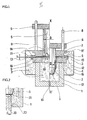
- Figure 1 shows, in section, a stamping tool comprising a centering ring according to the invention. This figure is cut in half along the axis XX '.
- the half-figure on the left represents the tool at the start of stamping, the half-figure on the right represents the same tool at the end of stamping.
- Figure 2 shows a detail of the tool which has been added an ejector.
- the level (11) of the liquid having stamped is above the upper plane of the stamping ring (2) and even of the blank (10) which is completely submerged.
- This blank is centered by a centering ring (12) according to the invention.
- the lateral clearance of the blank (10) in the ring (12) is only a few tenths of a millimeter.
- the ring (12) has eight radial holes (13) which allow the liquid levels inside and outside of the ring to equalize constantly, this although in the rest position the upper face (14 ) from the centering ring (12) emerges from the liquid (3) as shown in the left half-figure.
- the blank holder (7) to play its role, it must have a central allowance (15) which fits together with a play of a few tenths in the centering ring (12).
- the ring (12) is itself fixed according to a fitting (16) on the drawing ring.
- the liquid discharged from the pressure chamber (1) cannot escape directly to the tank (4) but must follow a winding path comprising a vertical portion first between the blank (10) and the ring (12) then between the blank holder (7) and the ring (12) before exiting towards the tank (4) through the holes (13).
- This rupture of the film would cause metal to metal contact between the blank (10) and the ring (2). It would therefore cause the breakage of the blank in the area where the deformation begins, giving rise to the skirt of the part (17).
- the stamped part (17) is a solid of revolution around the axis XX ', but by the process it is also possible to obtain objects the section of which by horizontal planes n is not circular, for example rectangular with rounded edges.
- the pressure chamber (1) finally has a drain opening (18) which can also be used for pump-controlled filling.
- the pressure rises rapidly in the chamber (1); the liquid (3) applies the blank (10) against the punch (5) and escapes under the collar (9) by applying it against the blank holder (7). It raises the level in the tank (4) to (11 ').
- the part (17) can then be ejected by any device, for example a spring device fixed to the bottom of the chamber (1).
- Stamping can be carried out very quickly without risk of bad centering, faulty filling of the chamber, or defective lubrication of the blank.
- radial holes (13) are advantageous to make radial holes (13) as numerous and wide as possible. It can be open channels at the upper part of the ring (12). It suffices that the upper face (14) of the ring (12) is visible so that the establishment of the blank is easy.
- the metal used was an aluminum alloy quality 3003.
- an ejector in the form of a cylindrical ring (19) similar to that shown in partial section in FIG. 2.
- This ejector (19) is applied from the start of stamping against the blank (10) opposite the punch (5) and accompanies the bottom of the case (17) during its descent into the chamber (1). Thanks to the seals (20) and (21), there is no liquid neither pressure between the blank (10) and the ejector (19) on a circle of diameter (d) inside the seal (21), The punch (5) has to overcome only the pressure exerted on an inner diameter (d) and outer diameter (D) crown.
- the ejector (19) is raised by ejecting the part (17).
- a liquid pressure limiter or regulator can be provided connected to an orifice such as the orifice (18) passing through the wall of the chamber (1).
- This process avoids greasing the blank before stamping and degreasing the part after stamping.
Landscapes
- Engineering & Computer Science (AREA)
- Mechanical Engineering (AREA)
- Shaping Metal By Deep-Drawing, Or The Like (AREA)
Applications Claiming Priority (2)
| Application Number | Priority Date | Filing Date | Title |
|---|---|---|---|
| FR7835301A FR2443888A1 (fr) | 1978-12-11 | 1978-12-11 | Emboutissage en matrice liquide |
| FR7835301 | 1978-12-11 |
Publications (1)
| Publication Number | Publication Date |
|---|---|
| EP0012702A1 true EP0012702A1 (fr) | 1980-06-25 |
Family
ID=9216151
Family Applications (1)
| Application Number | Title | Priority Date | Filing Date |
|---|---|---|---|
| EP79420066A Withdrawn EP0012702A1 (fr) | 1978-12-11 | 1979-12-06 | Procédé et dispositif pour emboutissage hydromécanique |
Country Status (10)
| Country | Link |
|---|---|
| US (1) | US4314468A (OSRAM) |
| EP (1) | EP0012702A1 (OSRAM) |
| JP (1) | JPS5581025A (OSRAM) |
| BE (1) | BE880561A (OSRAM) |
| CH (1) | CH632682A5 (OSRAM) |
| ES (1) | ES486718A1 (OSRAM) |
| FR (1) | FR2443888A1 (OSRAM) |
| GR (1) | GR66520B (OSRAM) |
| IT (1) | IT1126540B (OSRAM) |
| LU (1) | LU81978A1 (OSRAM) |
Families Citing this family (21)
| Publication number | Priority date | Publication date | Assignee | Title |
|---|---|---|---|---|
| JPS58181431A (ja) * | 1982-04-20 | 1983-10-24 | Kazuhiko Nakamura | 周液圧重畳式対向液圧成形法 |
| JPS60133933A (ja) * | 1983-12-21 | 1985-07-17 | Honda Motor Co Ltd | プレス成形法 |
| US5353618A (en) | 1989-08-24 | 1994-10-11 | Armco Steel Company, L.P. | Apparatus and method for forming a tubular frame member |
| US4989482A (en) * | 1989-11-17 | 1991-02-05 | Ti Corporate Services Limited | Method and apparatus for punching a hole in sheet material |
| US5157969A (en) * | 1989-11-29 | 1992-10-27 | Armco Steel Co., L.P. | Apparatus and method for hydroforming sheet metal |
| DE19928422A1 (de) * | 1999-06-23 | 2000-12-28 | Mueller Weingarten Maschf | Presse zum Außenhochdruckformen |
| KR100345288B1 (ko) * | 1999-07-06 | 2002-07-25 | 한국과학기술연구원 | 무금형 성형장치 |
| EP1292405B1 (en) * | 2000-06-19 | 2005-12-07 | CROWN Packaging Technology, Inc. | Drive for a hold down assembly of a can bodymaker and method of use thereof |
| US6631630B1 (en) * | 2000-09-22 | 2003-10-14 | Board Of Trustees Of Michigan State University | Hydroforming of composite materials |
| DE10110161A1 (de) * | 2001-03-02 | 2003-01-02 | Audi Ag | Umformwerkzeug zum hydromechanischen Tiefziehen von Werkstücken aus Blechzuschnitten |
| AT4663U3 (de) * | 2001-03-16 | 2002-03-25 | Hmt Umformtechnik Engineering | Einrichtung zur herstellung von werkstücken an presseinrichtungen |
| DE10205393B4 (de) * | 2002-02-09 | 2010-10-07 | Bayerische Motoren Werke Aktiengesellschaft | Verfahren zum Ziehen eines Blechbauteils |
| JP2006212695A (ja) * | 2005-02-07 | 2006-08-17 | Toyota Motor Corp | 液圧成形装置および液圧成形方法 |
| US7266982B1 (en) * | 2005-06-10 | 2007-09-11 | Guza David E | Hydroforming device and method |
| US7614270B2 (en) * | 2008-02-14 | 2009-11-10 | Ford Global Technologies, Llc | Method and apparatus for superplastic forming |
| US8596106B2 (en) * | 2008-05-21 | 2013-12-03 | The Hong Kong Polytechnic University | Isothermal forming system for production of sheet metal parts |
| US8534106B2 (en) * | 2009-10-19 | 2013-09-17 | Ford Global Technologies, Llc | Hydromechanical drawing process and machine |
| RU2486025C1 (ru) * | 2011-12-14 | 2013-06-27 | Федеральное государственное бюджетное образовательное учреждение высшего профессионального образования "Московский государственный технологический университет "СТАНКИН"" (ФГБОУ ВПО МГТУ "СТАНКИН") | Способ изготовления полых деталей |
| US20140020534A1 (en) * | 2012-07-17 | 2014-01-23 | National Taiwan Ocean University | Fine hydro-blanking device |
| US9713833B2 (en) * | 2015-09-20 | 2017-07-25 | Ahmad Shirazi | Hydro ironing |
| CN116351938B (zh) * | 2023-03-16 | 2024-03-19 | 江阴市伦一金属制品有限公司 | 一种汽车驱动电机用高强度无取向硅钢片的生产工艺及设备 |
Citations (5)
| Publication number | Priority date | Publication date | Assignee | Title |
|---|---|---|---|---|
| US3286496A (en) * | 1961-07-07 | 1966-11-22 | Siemens Elektrogeraete Gmbh | Apparatus for hydraulic deep-drawing of sheet metal |
| GB1142311A (en) * | 1965-02-17 | 1969-02-05 | Rheinmetall Gmbh | Improvements in or relating to smoke cartridges and to methods and apparatus for producing containers for said cartridges |
| FR1561102A (OSRAM) * | 1966-09-09 | 1969-03-28 | ||
| FR2124624A1 (OSRAM) * | 1971-02-10 | 1972-09-22 | Western Electric Co | |
| BE852015A (fr) * | 1977-03-02 | 1977-07-01 | Centre Rech Metallurgique | Perfectionnements aux procedes d'emboutissage de materiaux metalliques tels que des toles en acier |
Family Cites Families (6)
| Publication number | Priority date | Publication date | Assignee | Title |
|---|---|---|---|---|
| US3020633A (en) * | 1959-04-24 | 1962-02-13 | Olin Mathieson | Fabrication of hollow articles |
| US3383891A (en) * | 1965-10-20 | 1968-05-21 | Robert C. Geitz | Superhydraulic forging method and apparatus |
| US3516274A (en) * | 1967-02-15 | 1970-06-23 | Stanley Lewis Graham | Method and device for shaping metal |
| DE1777153C3 (de) * | 1968-09-12 | 1974-05-09 | Siemens-Electrogeraete Gmbh, 1000 Berlin U. 8000 Muenchen | Vorrichtung zum hydromechanischen Tiefziehen |
| US3748887A (en) * | 1971-10-01 | 1973-07-31 | Ladish Co | Method and apparatus for locating stock in forming dies |
| US3769824A (en) * | 1972-06-14 | 1973-11-06 | Armco Steel Corp | Deep drawing method |
-
1978
- 1978-12-11 FR FR7835301A patent/FR2443888A1/fr active Granted
-
1979
- 1979-11-29 US US06/098,559 patent/US4314468A/en not_active Expired - Lifetime
- 1979-12-06 EP EP79420066A patent/EP0012702A1/fr not_active Withdrawn
- 1979-12-07 IT IT27958/79A patent/IT1126540B/it active
- 1979-12-10 JP JP16020879A patent/JPS5581025A/ja active Pending
- 1979-12-10 CH CH1091579A patent/CH632682A5/fr not_active IP Right Cessation
- 1979-12-10 ES ES486718A patent/ES486718A1/es not_active Expired
- 1979-12-10 LU LU81978A patent/LU81978A1/fr unknown
- 1979-12-11 BE BE8/163A patent/BE880561A/fr not_active IP Right Cessation
- 1979-12-11 GR GR60729A patent/GR66520B/el unknown
Patent Citations (5)
| Publication number | Priority date | Publication date | Assignee | Title |
|---|---|---|---|---|
| US3286496A (en) * | 1961-07-07 | 1966-11-22 | Siemens Elektrogeraete Gmbh | Apparatus for hydraulic deep-drawing of sheet metal |
| GB1142311A (en) * | 1965-02-17 | 1969-02-05 | Rheinmetall Gmbh | Improvements in or relating to smoke cartridges and to methods and apparatus for producing containers for said cartridges |
| FR1561102A (OSRAM) * | 1966-09-09 | 1969-03-28 | ||
| FR2124624A1 (OSRAM) * | 1971-02-10 | 1972-09-22 | Western Electric Co | |
| BE852015A (fr) * | 1977-03-02 | 1977-07-01 | Centre Rech Metallurgique | Perfectionnements aux procedes d'emboutissage de materiaux metalliques tels que des toles en acier |
Non-Patent Citations (1)
| Title |
|---|
| MACHINE MODERNE, Septembre 1966, Paris FR E. BURCK: "Le procede d'emboutissage hydromecanique", pages 17-23. * L'ensemble de l'article * * |
Also Published As
| Publication number | Publication date |
|---|---|
| IT1126540B (it) | 1986-05-21 |
| FR2443888B1 (OSRAM) | 1982-03-26 |
| GR66520B (OSRAM) | 1981-03-24 |
| LU81978A1 (fr) | 1980-07-01 |
| JPS5581025A (en) | 1980-06-18 |
| ES486718A1 (es) | 1980-06-16 |
| BE880561A (fr) | 1980-06-11 |
| IT7927958A0 (it) | 1979-12-07 |
| CH632682A5 (fr) | 1982-10-29 |
| FR2443888A1 (fr) | 1980-07-11 |
| US4314468A (en) | 1982-02-09 |
Similar Documents
| Publication | Publication Date | Title |
|---|---|---|
| EP0012702A1 (fr) | Procédé et dispositif pour emboutissage hydromécanique | |
| FR2605910A1 (fr) | Procede et appareil pour former des panneau x d'extremites de recipients | |
| BE1003573A5 (fr) | Procede et appareil pour former un panneau d'extremite de recipient a partir d'une feuille de matiere. | |
| FR2516478A1 (fr) | Corps de recipient | |
| CH675380A5 (OSRAM) | ||
| FR2553686A1 (fr) | Procede d'usinage de pignon d'arbre primaire pour boite de vitesses de vehicule automobile | |
| FR2492690A1 (fr) | Procede et appareil pour le formage sous pression interne d'articles creux | |
| FR2532246A1 (fr) | Presse verticale executant plusieurs operations en une seule course | |
| EP0126015B1 (fr) | Procédé de sertissage d'un couvercle métallique | |
| CA2031859C (fr) | Procede et dispositif d'emboutissage de recipients de forme tronconique, et recipient ainsi embouti | |
| FR2523485A1 (fr) | Procede et appareil de formage d'une tole avec reduction importante | |
| EP0323931B1 (fr) | Procédé et outillage de fabrication de rivets matricés | |
| EP3496876B1 (fr) | Outil, dispositif et procédé de formage par emboutissage électrohydraulique indirect | |
| EP0678351B1 (fr) | Procédé de fabrication d'une poulie à gorges multiples, outil de formage mis en oeuvre par ce procédé et poulie ainsi obtenue | |
| FR3092504A1 (fr) | Procédé de formage hybride et dispositif de formage correspondant | |
| WO2016107888A1 (fr) | Dispositif d'electro-hydroformage | |
| FR2475947A1 (fr) | Procede de production d'articles creux par emboutissage profond, presse pour la mise en oeuvre de ce procede et articles creux obtenus | |
| FR2481190A1 (fr) | Outil de formage pour la fabrication par emboutissage de recipients en forme de coupe | |
| EP0148066A2 (fr) | Procédé et outillage de réalisation d'une roue de véhicule à jante amincie en une seule pièce d'acier | |
| EP3548198B1 (fr) | Outillage de presse pour la formation d'un collet par tombage | |
| FR2723867A1 (fr) | Procede d'emboutissage hydraulique a volume constant | |
| BE451677A (OSRAM) | ||
| FR2533472A1 (fr) | Procede pour l'assemblage etanche, par expansion de metal, de deux pieces metalliques et pieces assemblees conformement audit procede | |
| FR2975612A1 (fr) | Outil de faconnage d'une piece de tole | |
| BE507071A (OSRAM) |
Legal Events
| Date | Code | Title | Description |
|---|---|---|---|
| PUAI | Public reference made under article 153(3) epc to a published international application that has entered the european phase |
Free format text: ORIGINAL CODE: 0009012 |
|
| AK | Designated contracting states |
Designated state(s): DE GB NL SE |
|
| 17P | Request for examination filed | ||
| STAA | Information on the status of an ep patent application or granted ep patent |
Free format text: STATUS: THE APPLICATION IS DEEMED TO BE WITHDRAWN |
|
| 18D | Application deemed to be withdrawn |
Effective date: 19820705 |
|
| RIN1 | Information on inventor provided before grant (corrected) |
Inventor name: BARIL, JACQUES Inventor name: GABORIEAU, JEAN-YVES |