EP0011552B1 - Marine propeller with foldable blades - Google Patents
Marine propeller with foldable blades Download PDFInfo
- Publication number
- EP0011552B1 EP0011552B1 EP19790400834 EP79400834A EP0011552B1 EP 0011552 B1 EP0011552 B1 EP 0011552B1 EP 19790400834 EP19790400834 EP 19790400834 EP 79400834 A EP79400834 A EP 79400834A EP 0011552 B1 EP0011552 B1 EP 0011552B1
- Authority
- EP
- European Patent Office
- Prior art keywords
- propeller
- blades
- propeller shaft
- tip
- connecting member
- Prior art date
- Legal status (The legal status is an assumption and is not a legal conclusion. Google has not performed a legal analysis and makes no representation as to the accuracy of the status listed.)
- Expired
Links
- 230000007246 mechanism Effects 0.000 claims description 13
- 241000940835 Pales Species 0.000 description 8
- 206010033546 Pallor Diseases 0.000 description 8
- 238000010276 construction Methods 0.000 description 5
- 238000004519 manufacturing process Methods 0.000 description 4
- 241000920340 Pion Species 0.000 description 2
- 239000000463 material Substances 0.000 description 2
- 241000520223 Helice Species 0.000 description 1
- 240000008042 Zea mays Species 0.000 description 1
- 230000000903 blocking effect Effects 0.000 description 1
- 239000000470 constituent Substances 0.000 description 1
- 238000003754 machining Methods 0.000 description 1
- 229910001220 stainless steel Inorganic materials 0.000 description 1
- 239000010935 stainless steel Substances 0.000 description 1
- 239000013589 supplement Substances 0.000 description 1
Images

Classifications
-
- B—PERFORMING OPERATIONS; TRANSPORTING
- B63—SHIPS OR OTHER WATERBORNE VESSELS; RELATED EQUIPMENT
- B63H—MARINE PROPULSION OR STEERING
- B63H1/00—Propulsive elements directly acting on water
- B63H1/02—Propulsive elements directly acting on water of rotary type
- B63H1/12—Propulsive elements directly acting on water of rotary type with rotation axis substantially in propulsive direction
- B63H1/14—Propellers
- B63H1/20—Hubs; Blade connections
- B63H1/22—Hubs; Blade connections the blades being foldable
- B63H1/24—Hubs; Blade connections the blades being foldable automatically foldable or unfoldable
Definitions
- the invention relates to marine propellers with folding blades, that is to say to marine propellers whose branches can occupy either a rest position for which the blades are folded in the extension of the propeller shaft, or an active position for which the blades are deployed transversely relative to the propeller shaft.
- the blades move from their rest position to their active position is caused by the rotation of the propeller shaft (rotation which generates, on each blade, a centrifugal force) and the passage of the blades from their active position to their rest position is caused by the advancement of the boat (advancement which generates, on each blade, a drag force).
- the blades of the propeller are articulated with respect to the propeller shaft around a transverse axis and it is therefore conceivable that a synchronization mechanism must be provided between each blade to avoid any asymmetry of the propeller in case one (or more) blade remains trapped between its rest position and its active position.
- Mechanisms for synchronizing the movement of the blades have already been proposed, which are constituted by devices with toothed sectors or by connecting rod devices as described, for example, in the patents US-A-2,500,382 and DE-C-712,934 respectively. both relate to aerodyne propellers.
- the object of the invention is precisely to remedy these drawbacks.
- the propeller with folding blades comprises at least two blades articulated with respect to a propeller shaft, the aforementioned blades being able to move between two positions (rest position and active position), and a movement synchronization mechanism. blades for synchronizing their movement of movement between their two aforementioned positions, this synchronization mechanism comprising a connecting piece slidably mounted axially with respect to the propeller shaft and cooperating with each of the blades of the propeller, this propeller being characterized in that the feet of the propeller blades are housed in an axial slot in the end of the propeller shaft and are articulated, relative to the propeller shaft, by means of a single transverse axis.
- the propeller blades are arranged so as to be contiguous when they occupy their rest position.
- the invention consists, apart from the main arrangement which has just been mentioned, in certain other arrangements which are preferably used at the same time and which will be more explicitly discussed below.
- the blades 1 and 2 of the propeller are articulated relative to the propeller shaft 3 around a transverse axis 4 cooperating with a nozzle 3a carried by this propeller shaft 3.
- This tip can be arranged to constitute a propeller hub.
- the end piece 3a of the propeller shaft 3 has, at its end, an axial slot 5 in which the two blade feet 1a and 2a of the two blades 1 and 2 are housed respectively.
- a synchronization mechanism is provided between each of the two blades 1 and 2 to avoid any asymmetry of the propeller in the event that one of its two branches remains trapped between its rest position and its active position.
- This synchronization mechanism 6 is constituted by a connecting piece 7 slidably mounted axially in the end piece 3a of the propeller shaft 3.
- This connecting piece 7 cooperates with each of the blades 1 and 2 of the propeller, respectively by a connection to pin 8 and groove 9 in the case of blade 1, and to pin 10 and groove 11 in terms of blade 2.
- This connecting piece 7 has a narrowed portion 7a guided in a correspondingly shaped housing 12 formed in the end piece 3a of the propeller shaft 3 beyond the slot 5 presented by said end piece.
- This connecting piece 7 has a wide portion 7b located between the two blade feet 1 and 2a .
- This wide part 7b comprises the two grooves 9 and 11 with which the pins 8 and 10 cooperate respectively.
- transverse axis 4 extend through the parts of the end piece 3 a of the propeller shaft 3 located on either side of the slot 5, through the two blade feet 1a and 2a of the blades 1 and 2, as well as through the connecting piece 7.
- this connecting piece is provided with a light 13 axially elongated surrounding the transverse axis 4.
- the end piece 3a of the propeller shaft 3 is made integral with the latter by a conical fitting 14 and a nut 15.
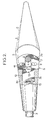
- the blades 1 and 2 of the propeller are arranged so as to be contiguous when they occupy their rest position (fig. 2).
Landscapes
- Chemical & Material Sciences (AREA)
- Engineering & Computer Science (AREA)
- Combustion & Propulsion (AREA)
- Mechanical Engineering (AREA)
- Ocean & Marine Engineering (AREA)
- Structures Of Non-Positive Displacement Pumps (AREA)
- Mixers Of The Rotary Stirring Type (AREA)
Description
L'invention est relative aux hélices marines à pales repliables, c'est-à-dire aux hélices marines dont les branches peuvent occuper, soit une position de repos pour laquelle les pales sont repliées dans le prolongement de l'arbre porte-hélice, soit une position active pour laquelle les pales sont déployées transversalement par rapport à l'arbre porte-hélice.The invention relates to marine propellers with folding blades, that is to say to marine propellers whose branches can occupy either a rest position for which the blades are folded in the extension of the propeller shaft, or an active position for which the blades are deployed transversely relative to the propeller shaft.
Dans de telles hélices, montées généralement sur des voiliers à moteur auxiliaire intérieur, le passage des pales de leur position de repos à leur position active est provoqué par la mise en rotation de l'arbre porte-hélice (mise en rotation qui engendre, sur chaque pale, une force centrifuge) et le passage des pales de leur position active à leur position de repos est provoqué par l'avancement du bateau (avancement qui engendre, sur chaque pale, une force de trainée).In such propellers, generally mounted on sailboats with an internal auxiliary motor, the blades move from their rest position to their active position is caused by the rotation of the propeller shaft (rotation which generates, on each blade, a centrifugal force) and the passage of the blades from their active position to their rest position is caused by the advancement of the boat (advancement which generates, on each blade, a drag force).
A cet effet, les pales de l'hélice sont articulées par rapport à l'arbre porte-hélice autour d'un axe transversal et on conçoit alors qu'il faut prévoir un mécanisme de synchronisation entre chaque pale pour éviter toute dissymétrie de l'hélice au cas où une (ou plusieurs) pale resterait coincée entre sa position de repos et sa position active.To this end, the blades of the propeller are articulated with respect to the propeller shaft around a transverse axis and it is therefore conceivable that a synchronization mechanism must be provided between each blade to avoid any asymmetry of the propeller in case one (or more) blade remains trapped between its rest position and its active position.
On a déjà proposé des mécanismes de synchronisation du mouvement des pales qui sont constitués par des dispositifs à secteurs dentés ou par des dispositifs à biellettes comme décrit, par exemple, respectivement dans les brevets US-A-2,500,382 et DE-C-712 934 qui ont tous deux trait à des hélices d'aérodyne.Mechanisms for synchronizing the movement of the blades have already been proposed, which are constituted by devices with toothed sectors or by connecting rod devices as described, for example, in the patents US-A-2,500,382 and DE-C-712,934 respectively. both relate to aerodyne propellers.
Cependant, ces mécanismes de synchronisation présentent divers inconvénients, notamment en ce qui concerne leur complexité, leur manque de protection par rapport aux coquillages et/ou à la végétation sous-marine, leur tendance à se coincer, leur encombrement lorsque les pales occupent leur position de repos.However, these synchronization mechanisms have various drawbacks, in particular with regard to their complexity, their lack of protection with regard to shells and / or underwater vegetation, their tendency to get stuck, their size when the blades occupy their position. rest.
L'invention a précisément pour but de remédier à ces inconvénients.The object of the invention is precisely to remedy these drawbacks.
L'hélice à pales repliables conforme à l'invention comporte au moins deux pales articulées par rapport à un arbre porte-hélice, les susdites pales pouvant évoluer entre deux positions (position de repos et position active), et un mécanisme de synchronisation du mouvement des pales pour synchroniser leur mouvement de débattement entre leurs deux susdites positions, ce mécanisme de synchronisation comprenant une pièce de liaison montée coulissante axialement par rapport à l'arbre porte-hélice et coopérant avec chacune des pales de l'hélice, cette hélice étant caractérisée en ce que les pieds des pales de l'hélice sont logés dans une fente axiale de l'extrémité de l'arbre porte-hélice et sont articulés, par rapport à l'arbre porte-hélice, par l'intermédiaire d'un seul axe transversal.The propeller with folding blades according to the invention comprises at least two blades articulated with respect to a propeller shaft, the aforementioned blades being able to move between two positions (rest position and active position), and a movement synchronization mechanism. blades for synchronizing their movement of movement between their two aforementioned positions, this synchronization mechanism comprising a connecting piece slidably mounted axially with respect to the propeller shaft and cooperating with each of the blades of the propeller, this propeller being characterized in that the feet of the propeller blades are housed in an axial slot in the end of the propeller shaft and are articulated, relative to the propeller shaft, by means of a single transverse axis.
De préférence, les pales de l'hélice sont agencées de façon à être jointives lorsqu'elles occupent leur position de repos.Preferably, the propeller blades are arranged so as to be contiguous when they occupy their rest position.
On conçoit alors qu'on dispose d'une hélice qui présente les avantages suivants:
- - l'hélice est de construction simple puisqu'elle comporte un seul axe transversal de pivotement alors que les hélices selon l'art antérieur comportaient généralement un axe de pivotement par pale;
- - le mécanisme de synchronisation de l'hélice est bien protégé (surtout lorsque les pales de l'hélice sont jointives lorsqu'elles occupent leur position de repos) contre les coquillages et/ou la végétation sous-marine puiseque ce mécanisme peut être logé dans les pieds de pales et dans l'arbre porte-hélice ou dans son embout qui peut être agencé pour constituer un moyeu d'hélice;
- -l'hélice présente des caractéristiques de fiabilité éliminant pratiquement toute tendance à se coincer;
- - l'hélice présente un encombrement très faible en position de repos;
- - l'helice comporte deux pales d'un seul type;
- - les moyens de blocage de l'axe trans- verasl autorisant le pivotement des pales de l'hélice peuvent être réalisés très simplement;
- - la construction de l'hélice est simplifiée, notamment en raison du fait qu'il est prévu un seul axe de pivotement;
- - il est possible de réaliser toutes les pièces constitutives de l'hélice en un même matériau, ce qui permet d'éviter les couples électrolytiques (il convient de noter que cette possibilité n'était pas toujours réalisable avec les mécanismes connus jusqu'à ce jour qui étaient plus complexes et qui impliquaient la réalisation de pièces en matériau résistant, tel par exemple que l'acierinoxydable),
- - la réalisation des pièces constitutives de l'hélice est simplifiée du fait que la totalité de ces pièces peut venir directement de fonderie avec un minimum d'usinage; on peut donc obtenir un prix de fabrication réduit.
- - The propeller is of simple construction since it has a single transverse pivot axis while the propellers according to the prior art generally included a pivot axis per blade;
- - the propeller synchronization mechanism is well protected (especially when the propeller blades are contiguous when they occupy their rest position) against shells and / or underwater vegetation since this mechanism can be housed in the blade feet and in the propeller shaft or in its endpiece which can be arranged to constitute a propeller hub;
- the propeller has reliability characteristics which virtually eliminate any tendency to get stuck;
- - The propeller has a very small footprint in the rest position;
- - the propeller comprises two blades of a single type;
- the means for blocking the transverse axis allowing the blades of the propeller to pivot can be made very simply;
- - The construction of the propeller is simplified, in particular because of the fact that there is only one pivot axis;
- - it is possible to make all the constituent parts of the propeller in the same material, which makes it possible to avoid electrolytic couples (it should be noted that this possibility was not always achievable with the mechanisms known until which were more complex and which involved the production of parts made of resistant material (such as stainless steel),
- - The production of the component parts of the propeller is simplified by the fact that all of these parts can come directly from the foundry with a minimum of machining; we can therefore obtain a reduced manufacturing price.
Il résulte de ces avantages qu'on dispose d'une hélice dont les pales se présentent toujours symétriquement par rapport à l'arbre porte-hélice, ce qui évite tout risque de balourd particul-ièrement gênant lorsque l'hélice est entrainée en rotation par l'arbre porte-hélice.It follows from these advantages that there is a propeller whose blades are always symmetrically with respect to the propeller shaft, which avoids any risk of unbalance particularly annoying when the propeller is rotated by the propeller shaft.
L'invention consiste, mise à part la disposition principale dont il vient d'être question, en certaines autres dispositions qui s'utilisent de préférence en même temps et dont il sera plus explicitement parlé ci-après.The invention consists, apart from the main arrangement which has just been mentioned, in certain other arrangements which are preferably used at the same time and which will be more explicitly discussed below.
L'invention sera, de toute façon, mieux comprise à l'aide du complément de description qui suit ainsi que des dessins ci-annexés, lesquels complément et dessins sont relatifs à un mode de réalisation préféré de l'invention et ne comportent aucun caractère limitatif.
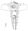
- La fig. 1, de ces dessins, est une vue en coupe axiale d'une hélice établie conformément à l'invention, les pales de cette hélice étant montrées en position active.
- La fig. 2 montre la même hélice dans les mêmes conditions mais les pales dans leur position de repos.
- La fig. 3 est une coupe selon III―III fig. 1.
- Fig. 1, of these drawings, is an axial sectional view of a propeller established in accordance with the invention, the blades of this propeller being shown in the active position.
- Fig. 2 shows the same propeller under the same conditions but the blades in their rest position.
- Fig. 3 is a section on III ― III fig. 1.
L'hélice montrée sur les fig. 1 à 3 comporte deux pales 1 et 2 qui peuvent occuper,
- -soit une position de repos (fig. 2) pour laquelle les
pales 1 et 2 sont repliées dans le prolongement de l'arbre porte-hélice 3, - - soit une position active (fig. 1) pour laquelle les
pales 1 et 2 sont déployées transversalement par rapport à l'arbre porte-hélice 3.
- -or a rest position (fig. 2) for which the
blades propeller shaft 3, - - either an active position (fig. 1) for which the
blades propeller shaft 3.
Les pales 1 et 2 de l'hélice sont articulées par rapport à l'arbre porte-hélice 3 autour d'un axe transversal 4 coopérant avec un embout 3a porté par cet arbre porte-hélice 3.The
Cet embout peut être agencé pour constituer un moyeu d'hélice.This tip can be arranged to constitute a propeller hub.
A cet effet et comme montré clairement sur la fig. 3, l'embout 3a de l'arbre porte-hélice 3 présente, à son extrémité, une fente axiale 5 dans laquelle viennent se loger respectivement les deux pieds de pales 1 a et 2a des deux pales 1 et 2.For this purpose and as clearly shown in FIG. 3, the
Un mécanisme de synchronisation, désigné d'une façon générale par le chiffre de référence 6, est prévu entre chacune des deux pales 1 et 2 pour éviter toute dissymétrie de l'hélice au cas où l'une de ses deux branches resterait coincée entre sa position de repos et sa position active.A synchronization mechanism, generally designated by the reference numeral 6, is provided between each of the two
Ce mécanisme de synchronisation 6 est constitué par une pièce de liaison 7 montée coulissante axialement dans l'embout 3a de l'arbre porte-hélice 3.This synchronization mechanism 6 is constituted by a connecting piece 7 slidably mounted axially in the
Cette pièce de liaison 7 coopère avec chacune des pales 1 et 2 de l'hélice, respectivement par une liaison à pion 8 et gorge 9 pour ce qui est de la pale 1, et à pion 10 et gorge 11 pour ce qui est de la pale 2.This connecting piece 7 cooperates with each of the
Cette pièce de liaison 7 comporte une partie rétrécie 7a guidée dans un logement de forme correspondante 12 ménagé dans l'embout 3a de l'arbre porte-hélice 3 au-delà de la fente 5 que présente ledit embout.This connecting piece 7 has a narrowed
Cette pièce de liaison 7 comporte une partie large 7b située entre les deux pieds de pales 1 et 2a.This connecting piece 7 has a wide portion 7b located between the two
Cette partie large 7b comprend les deux gorges 9 et 11 avec lesquelles coopèrent respectivement les pions 8 et 10.This wide part 7b comprises the two
Ces deux pions 8 et 10 sont portés,
- - pour le
pion 8, par le pied depale 1 a de lapale 1, - ― et, pour le
pion 10, par le pied de pale 2a de lapale 2.
- - for
pin 8, byblade root 1a ofblade 1, - - And, for the
pin 10, by the blade root 2a of theblade 2.
Au point de vue simplicité de construction, il est avantageux que l'axe transversal 4 s'étende à travers les parties de l'embout 3a de l'arbre porte-hélice 3 situées de part et d'autre de la fente 5, à travers les deux pieds de pales 1 a et 2a des pales 1 et 2, ainsi qu'à travers la pièce de liaison 7.From the point of view of simplicity of construction, it is advantageous for the
Ceci étant et pour autoriser le coulissement de cette pièce de liaison, celle-ci est munie d'une lumière 13 allongée axialement entourant l'axe transversal 4.This being the case, and in order to allow this connecting piece to slide, it is provided with a
De façon en soi connue, l'embout 3a de l'arbre porte-hélice 3 est rendu solidaire de ce dernier par un emmanchement conique 14 et un écrou 15.In known manner, the
De préférence et comme il a déjà été indiqué ci-dessus, les pales 1 et 2 de l'hélice sont agencées de façon à être jointives lorsqu'elles occupent leur position de repos (fig. 2).Preferably and as already indicated above, the
Claims (7)
Applications Claiming Priority (2)
| Application Number | Priority Date | Filing Date | Title |
|---|---|---|---|
| FR7831593 | 1978-11-08 | ||
| FR7831593A FR2440869A1 (en) | 1978-11-08 | 1978-11-08 | IMPROVEMENTS TO MARINE PROPELLERS WITH FOLDABLE BLADES |
Publications (2)
| Publication Number | Publication Date |
|---|---|
| EP0011552A1 EP0011552A1 (en) | 1980-05-28 |
| EP0011552B1 true EP0011552B1 (en) | 1983-10-19 |
Family
ID=9214614
Family Applications (1)
| Application Number | Title | Priority Date | Filing Date |
|---|---|---|---|
| EP19790400834 Expired EP0011552B1 (en) | 1978-11-08 | 1979-11-08 | Marine propeller with foldable blades |
Country Status (3)
| Country | Link |
|---|---|
| EP (1) | EP0011552B1 (en) |
| DE (1) | DE2966338D1 (en) |
| FR (1) | FR2440869A1 (en) |
Cited By (1)
| Publication number | Priority date | Publication date | Assignee | Title |
|---|---|---|---|---|
| US6972956B2 (en) | 2003-01-16 | 2005-12-06 | Hewlett-Packard Development Company, L.P. | Collapsible fan and system and method incorporating same |
Family Cites Families (3)
| Publication number | Priority date | Publication date | Assignee | Title |
|---|---|---|---|---|
| DE411631C (en) * | 1924-06-13 | 1925-03-28 | Hellmuth Hirth | Auxiliary propeller for gliders |
| DE712934C (en) * | 1936-07-01 | 1941-10-29 | Hermann Dorner Dipl Ing | Double-bladed propeller with blades that can be pivoted into the rotating axis of the screw |
| US2500382A (en) * | 1945-07-20 | 1950-03-14 | Elton H Rowley | Folding propeller |
-
1978
- 1978-11-08 FR FR7831593A patent/FR2440869A1/en active Granted
-
1979
- 1979-11-08 DE DE7979400834T patent/DE2966338D1/en not_active Expired
- 1979-11-08 EP EP19790400834 patent/EP0011552B1/en not_active Expired
Cited By (1)
| Publication number | Priority date | Publication date | Assignee | Title |
|---|---|---|---|---|
| US6972956B2 (en) | 2003-01-16 | 2005-12-06 | Hewlett-Packard Development Company, L.P. | Collapsible fan and system and method incorporating same |
Also Published As
| Publication number | Publication date |
|---|---|
| DE2966338D1 (en) | 1983-11-24 |
| EP0011552A1 (en) | 1980-05-28 |
| FR2440869B1 (en) | 1981-12-31 |
| FR2440869A1 (en) | 1980-06-06 |
Similar Documents
| Publication | Publication Date | Title |
|---|---|---|
| EP0357494B1 (en) | Thrust reverser with auxiliary flaps for a jet engine | |
| FR2612249A1 (en) | MOBILE AUBAGE FOR STEAM TURBINES | |
| EP0011582B1 (en) | Improvement in roller reefing systems | |
| FR2835562A1 (en) | STATOR BLADE SWIVEL ARRANGEMENT IN A TURBOMACHINE | |
| CA2470089C (en) | Guiding device for a blade with variable blade angle | |
| CA2472876C (en) | Turbojet nacelle hood locking mechanism | |
| FR2473462A1 (en) | FOLDING BOAT PROPELLER | |
| EP0011552B1 (en) | Marine propeller with foldable blades | |
| EP2295928B1 (en) | Device for deploying and locking of a canard wing | |
| EP0428480B1 (en) | Plate safety binding | |
| EP1057954B1 (en) | Electromagnetic security lock | |
| EP1535119B1 (en) | Wristwatch | |
| WO2006063781A1 (en) | Arrangement for self-releasing connection of a windscreen wiper arm on a driving shaft | |
| FR2607107A1 (en) | HELICOPTER ROTOR | |
| FR2573489A1 (en) | Electrical pump for liquids | |
| FR2571021A1 (en) | DEVICE FOR THE AUTOMATIC CONTROL OF AERODYNAMIC COMPENSATOR ASSOCIATED WITH AERODYNAMIC CONTROL SURFACE OF AN AIRCRAFT | |
| EP4257004B1 (en) | Bracelet clasp | |
| FR2568131A1 (en) | Ice piton | |
| FR2765549A1 (en) | STABILIZATION DEVICE FOR SAILING BOAT | |
| EP3650953B1 (en) | Timepiece mechanism comprising a star and a jumper spring | |
| CA2789462A1 (en) | Turboprop provided with a blade-positioning device | |
| FR2951397A1 (en) | Knife for edging thermoformed or flexibly injected plastic pieces of laminated windscreens, comprises elongated body whose rear part forms handle and front part forms a blade according to respective longitudinal axes, and hinged cover | |
| FR3066174B1 (en) | PEDALO WITH ELECTRICAL ASSISTANCE, EQUIPPED WITH A DEVICE FOR LIFTING / IMMERSION OF ITS PROPULSION PROPELLER | |
| CH719582A2 (en) | Bracelet clasp. | |
| FR2797946A1 (en) | Fin mounting for tube launched missile munition has rotary support mounted in fuselage to carry fin via secondary pivot |
Legal Events
| Date | Code | Title | Description |
|---|---|---|---|
| PUAI | Public reference made under article 153(3) epc to a published international application that has entered the european phase |
Free format text: ORIGINAL CODE: 0009012 |
|
| AK | Designated contracting states |
Designated state(s): DE GB IT NL SE |
|
| 17P | Request for examination filed |
Effective date: 19800423 |
|
| ITF | It: translation for a ep patent filed | ||
| GRAA | (expected) grant |
Free format text: ORIGINAL CODE: 0009210 |
|
| RAP1 | Party data changed (applicant data changed or rights of an application transferred) |
Owner name: FRANCE HELICES |
|
| AK | Designated contracting states |
Designated state(s): DE GB IT NL SE |
|
| REF | Corresponds to: |
Ref document number: 2966338 Country of ref document: DE Date of ref document: 19831124 |
|
| PLBE | No opposition filed within time limit |
Free format text: ORIGINAL CODE: 0009261 |
|
| STAA | Information on the status of an ep patent application or granted ep patent |
Free format text: STATUS: NO OPPOSITION FILED WITHIN TIME LIMIT |
|
| PGFP | Annual fee paid to national office [announced via postgrant information from national office to epo] |
Ref country code: DE Payment date: 19840921 Year of fee payment: 6 |
|
| PGFP | Annual fee paid to national office [announced via postgrant information from national office to epo] |
Ref country code: SE Payment date: 19840930 Year of fee payment: 6 |
|
| 26N | No opposition filed | ||
| PGFP | Annual fee paid to national office [announced via postgrant information from national office to epo] |
Ref country code: NL Payment date: 19851130 Year of fee payment: 7 |
|
| PG25 | Lapsed in a contracting state [announced via postgrant information from national office to epo] |
Ref country code: SE Effective date: 19861109 |
|
| PG25 | Lapsed in a contracting state [announced via postgrant information from national office to epo] |
Ref country code: NL Effective date: 19870601 |
|
| NLV4 | Nl: lapsed or anulled due to non-payment of the annual fee | ||
| GBPC | Gb: european patent ceased through non-payment of renewal fee | ||
| PG25 | Lapsed in a contracting state [announced via postgrant information from national office to epo] |
Ref country code: DE Effective date: 19870801 |
|
| PG25 | Lapsed in a contracting state [announced via postgrant information from national office to epo] |
Ref country code: GB Effective date: 19881118 |
|
| EUG | Se: european patent has lapsed |
Ref document number: 79400834.2 Effective date: 19870812 |