EP1535119B1 - Wristwatch - Google Patents
Wristwatch Download PDFInfo
- Publication number
- EP1535119B1 EP1535119B1 EP03769577A EP03769577A EP1535119B1 EP 1535119 B1 EP1535119 B1 EP 1535119B1 EP 03769577 A EP03769577 A EP 03769577A EP 03769577 A EP03769577 A EP 03769577A EP 1535119 B1 EP1535119 B1 EP 1535119B1
- Authority
- EP
- European Patent Office
- Prior art keywords
- bracelet
- connection element
- watch bracelet
- watch
- main
- Prior art date
- Legal status (The legal status is an assumption and is not a legal conclusion. Google has not performed a legal analysis and makes no representation as to the accuracy of the status listed.)
- Expired - Lifetime
Links
- 230000000295 complement effect Effects 0.000 claims description 2
- 238000006073 displacement reaction Methods 0.000 claims description 2
- 210000000707 wrist Anatomy 0.000 abstract description 5
- 230000037230 mobility Effects 0.000 description 4
- 238000002955 isolation Methods 0.000 description 1
- 239000010985 leather Substances 0.000 description 1
- 239000002184 metal Substances 0.000 description 1
- 238000000034 method Methods 0.000 description 1
- 238000004804 winding Methods 0.000 description 1
Images


Classifications
-
- G—PHYSICS
- G04—HOROLOGY
- G04B—MECHANICALLY-DRIVEN CLOCKS OR WATCHES; MECHANICAL PARTS OF CLOCKS OR WATCHES IN GENERAL; TIME PIECES USING THE POSITION OF THE SUN, MOON OR STARS
- G04B37/00—Cases
- G04B37/14—Suspending devices, supports or stands for time-pieces insofar as they form part of the case
- G04B37/1486—Arrangements for fixing to a bracelet
Definitions
- the present invention relates to a wristwatch intended to be worn on the wrist of a user.
- a wristwatch is a watch mounted on a bracelet that can be made for example of leather, metal and / or plastic.
- a wristwatch is essentially composed of a dial case containing a clockwork movement, as well as a removable bracelet whose ends are reversibly fixed to the middle of the box.
- the box is generally provided with two pairs of horns, forming connecting elements, which are respectively integral with two opposite sides of the middle and which extend in the same direction but in opposite directions as indicated, for example, in the document CH 331316 .
- the free end of each horn generally comprises a blind bore for receiving the end of a telescopic axis, commonly called pump, itself secured to one end of the bracelet.
- This type of wristwatch however has the disadvantage of not being always very comfortable to wear since it has a portion of relatively large dimensions, the structural rigidity does not allow the wristwatch to easily adapt to the wrist size of the user.
- This rigid part corresponds to the middle part combined with the two pairs of connecting horns. Of course, it is essentially these two pairs of horns, arranged cantilevered with respect to the middle part, which generate an excessive length to the rigid part of the wristwatch.
- the technical problem to be solved by the object of the present invention is to propose a wristwatch having a middle and a removable bracelet, each end of the bracelet being secured to the respective free ends of two connecting elements integral with the middle part, a wristwatch which would make it possible to avoid the problems of the state of the art by being able to best adapt to the wearer's morphology, while offering a significantly improved user comfort.
- each connecting element is mounted movably in displacement relative to the middle part, the free end of each connecting element being capable of being oriented in different directions.
- the invention as thus defined has the advantage of reducing the dimensions of the rigid part of the wristwatch.
- the cantilever connecting elements are not here rigidly attached to the middle part. Due to their relative mobility, each connecting element is able to orient itself naturally in a direction substantially tangent to the curvature of the wrist of the user.
- the assembly, formed by the middle part and the connecting elements, thus offers a sufficiently flexible structure to be able to marry at best the wrist of the user, resulting in a greatly improved user comfort.
- the present invention also relates to the features which will emerge during the following description, which should be considered in isolation or in all their possible technical combinations.
- the figure 1 illustrates a wristwatch 1 essentially composed of a dial box 2 and a removable bracelet 3.
- the box 2 comprises a caseband 4 containing a clockwork movement not shown here for the sake of clarity.
- the ends 5, 6 of the bracelet 3 are removably attached to the middle part 4, in particular by means of two pairs of connecting elements 10, 30; 20, 40 respectively disposed in opposition on the periphery 7 of said caseband 4. Note also the presence of a winding 8.
- each connecting element 10, 20, 30, 40 is movably mounted relative to the middle part 4.
- the free end 11, 21, 31, 41 of each connecting element 10 , 20, 30, 40 is thus capable of being oriented in different directions.
- each connecting element 10, 20, 30, 40 is articulated so as to extend in any direction included in a cone whose vertex is located in the middle part 4.
- each connecting element 10, 20, 30, 40 comprises a spherical portion 12, 22, 32, 42 forming a ball joint, and a radial portion 13, 23, 33, 43 provided with a first assembly means 14, 24, 34, 44.
- the spherical portion 12, 22, 32, 42 is rotatably shaped in a hollow seat housing 15, 25, 35, 45.
- the first assembly means 14, 24, 34, 44 is itself configured so as to cooperate by fixing with a second assembly means 50, 60 secured to the corresponding free end 5, 6 of the bracelet 3.
- the hollow housing 15, 25, 35, 45 is constituted, on the one hand, by a substantially hemispherical cavity 16, 26, 36, 46 formed in the middle part 4, and on the other hand, by a removable yoke 17, 27, 37, 47 whose internal face has a shape substantially complementary to the spherical portion 12, 22, 32, 42 when said spherical portion 12, 22, 32, 42 is housed in said hemispherical cavity 16, 26, 36, 46.
- the removable yoke 17, 27, 37, 47 further comprises an opening 18, 28, 38, 48 allowing the passage of the radial portion 13, 23, 33, 43, and consequently the mobility of the connecting element 10, 20, 30, 40 corresponding.
- each yoke 17, 27, 37, 47 is secured to the middle part 4 by fastening screws not shown in the various figures, again for the sake of clarity.
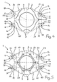
- each connecting element 10, 20, 30, 40 has several mobilities. So, and as we can see on the figure 3 each connecting element 10, 20, 30, 40 is able to tilt vertically about 90 °. In this embodiment, each connecting element 10, 20, 30, 40 is more precisely able to swing vertically with respect to the plane of the wristwatch, about 30 ° upwards as in the case of the connecting element 40, and up to about 60 ° downwards as for the element of the wristwatch. liaison 30.
- each connecting element 10, 20, 30, 40 is also capable of tilting horizontally about 35 °.
- each connecting element 10, 20, 30, 40 is thus able to tilt horizontally up to 5 ° inwards and 30 ° outwards, with respect to a plane P which is orthogonal to the plane of the wristwatch 1 on the one hand, and orthogonal to the sagittal plane S passing through the winder on the other hand.
- This feature is particularly advantageous to compensate for possible assembly gaps that may exist between the first assembly means 14, 24, 34, 44 and the second assembly means 50, 60 associated.
- each connecting element 10, 20, 30, 40 is furthermore able to rotate axially on itself, ie around the direction in which said connecting element 10, 20, 30, 40 is extends.
- each first assembly means 14, 24, 34, 44 and each second assembly means 50, 60 is constituted by a through bore, forming a bearing 19, 29, 39, 49, which is adapted to cooperate with a connecting pin 51, 61, forming second connecting means 50, 60.
- Each connecting pin 51 ; 61 is held in two corresponding bearings 19, 39; 29, 49 by means of two locking screws 52a, 52b; 62a, 62b forming a stop at the respective ends of each connecting pin 51; 61. All known assembly techniques, equivalent to those linking the first assembly means 14, 24, 34, 44 to the second fastening means 50, 60, can obviously be adopted as long as the assembly function is well filled.
- the figure 5 shows more specifically the lower part of each yoke 17, 27, 37, 47. It also makes it possible to observe the presence of a bottom 9 allowing access to the inside of the box 2, from below the watch. bracelet 1. This bottom 9 is also attached to the lower edge of the middle part 4 by a set of fixing screws.
Abstract
Description
La présente invention concerne une montre-bracelet destinée à être portée au poignet d'un utilisateur.The present invention relates to a wristwatch intended to be worn on the wrist of a user.
Comme son nom l'indique, une montre-bracelet est une montre montée sur un bracelet qui peut être réalisé par exemple en cuir, en métal et/ou en matière plastique. Une telle montre-bracelet est essentiellement composée d'une boîte à cadran contenant un mouvement d'horlogerie, ainsi que d'un bracelet amovible dont les extrémités sont fixées de manière réversible à la carrure de la boîte. Pour cela, la boîte est généralement dotée de deux paires de cornes, formant éléments de liaison, qui sont respectivement solidaires de deux cotés opposés de la carrure et qui s'étendent suivant une même direction mais dans des sens contraires comme indiqué, par example, dans le document
Ce type de montre-bracelet présente toutefois l'inconvénient de ne pas être toujours très confortable à porter puisqu'elle présente une partie, de dimensions relativement importantes, dont la rigidité structurelle ne permet pas à la montre-bracelet de s'adapter facilement à la taille du poignet de l'utilisateur. Cette partie rigide correspond à la carrure combinée au deux paires de cornes de liaison. Bien entendu, ce sont essentiellement ces deux paires de cornes, disposées en porte-à-faux par rapport à la carrure, qui génèrent une longueur excessive à la partie rigide de la montre-bracelet.This type of wristwatch however has the disadvantage of not being always very comfortable to wear since it has a portion of relatively large dimensions, the structural rigidity does not allow the wristwatch to easily adapt to the wrist size of the user. This rigid part corresponds to the middle part combined with the two pairs of connecting horns. Of course, it is essentially these two pairs of horns, arranged cantilevered with respect to the middle part, which generate an excessive length to the rigid part of the wristwatch.
Aussi le problème technique à résoudre, par l'objet de la présente invention, est de proposer une montre-bracelet comportant une carrure et un bracelet amovible, chaque extrémité du bracelet étant solidarisée aux extrémités libres respectives de deux éléments de liaison solidaires de la carrure, montre-bracelet qui permettrait d'éviter les problèmes de l'état de la technique en étant capable de s'adapter au mieux à la morphologie du porteur, tout en offrant un confort d'utilisation sensiblement amélioré.Also the technical problem to be solved by the object of the present invention is to propose a wristwatch having a middle and a removable bracelet, each end of the bracelet being secured to the respective free ends of two connecting elements integral with the middle part, a wristwatch which would make it possible to avoid the problems of the state of the art by being able to best adapt to the wearer's morphology, while offering a significantly improved user comfort.
La solution au problème technique posé consiste, selon la présente invention, définie dans la revendication 1, en ce que chaque élément de liaison est monté mobile en déplacement par rapport à la carrure, l'extrémité libre de chaque élément de liaison étant apte à être orientée dans différentes directions.The solution to the technical problem posed, according to the present invention, defined in claim 1, in that each connecting element is mounted movably in displacement relative to the middle part, the free end of each connecting element being capable of being oriented in different directions.
L'invention telle qu'ainsi définie présente l'avantage de réduire les dimensions de la partie rigide de la montre-bracelet. En effet, les éléments de liaison en porte-à-faux ne sont pas ici solidarisés de manière rigide à la carrure. Grâce à leur mobilité relative, chaque élément de liaison est en mesure de s'orienter naturellement suivant une direction sensiblement tangente à la courbure du poignet de l'utilisateur. L'ensemble, formé par la carrure et les éléments de liaison, offre ainsi une structure suffisamment flexible pour pouvoir épouser au mieux le poignet de l'utilisateur, d'où un confort d'utilisation grandement amélioré.The invention as thus defined has the advantage of reducing the dimensions of the rigid part of the wristwatch. Indeed, the cantilever connecting elements are not here rigidly attached to the middle part. Due to their relative mobility, each connecting element is able to orient itself naturally in a direction substantially tangent to the curvature of the wrist of the user. The assembly, formed by the middle part and the connecting elements, thus offers a sufficiently flexible structure to be able to marry at best the wrist of the user, resulting in a greatly improved user comfort.
La présente invention concerne également les caractéristiques qui ressortiront au cours de la description qui va suivre, et qui devront être considérées isolément ou selon toutes leurs combinaisons techniques possibles.The present invention also relates to the features which will emerge during the following description, which should be considered in isolation or in all their possible technical combinations.
Cette description donnée à titre d'exemple non limitatif, fera mieux comprendre comment l'invention peut être réalisée, en référence aux dessins annexés sur lesquels:
- La
figure 1 est une vue de dessus d'une montre-bracelet conforme à l'invention. - La
figure 2 constitue un éclaté montrant plus en détail la carrure et les éléments de liaison de la montre-bracelet de lafigure 1 . - La
figure 3 représente, en coupe longitudinale, la montre-bracelet de lafigure 1 . - La
figure 4 est une vue de dessus de la montre-bracelet de lafigure 1 , illustrant certaines mobilités des éléments de liaison lorsque le bracelet n'est pas solidaire de la carrure. - La
figure 5 constitue une vue de dessous de la montre-bracelet représentée à lafigure 4 .
- The
figure 1 is a top view of a wristwatch according to the invention. - The
figure 2 constitutes an exploded showing in more detail the middle and connecting elements of the wristwatch of thefigure 1 . - The
figure 3 represents, in longitudinal section, the wristwatch of thefigure 1 . - The
figure 4 is a top view of the wristwatch of thefigure 1 , illustrating certain mobilities of the connecting elements when the bracelet is not secured to the middle part. - The
figure 5 is a bottom view of the wristwatch shown in thefigure 4 .
Pour des raisons de clarté, les mêmes éléments ont été désignés par des références identiques. De même, seuls les éléments essentiels pour la compréhension de l'invention ont été représentés, et ceci sans respect de l'échelle et de manière schématique.For the sake of clarity, the same elements have been designated by identical references. Likewise, only the essential elements for understanding the invention have been represented, and this without regard to the scale and in a schematic manner.
La
Conformément à l'objet de la présente invention, chaque élément de liaison 10, 20, 30, 40 est monté mobile en déplacement par rapport à la carrure 4. L'extrémité libre 11, 21, 31, 41 de chaque élément de liaison 10, 20, 30, 40 est ainsi susceptible d'être orientée dans différentes directions. Dans cet exemple de réalisation, chaque élément de liaison 10, 20, 30, 40 est articulé de manière à pouvoir s'étendre suivant toute direction comprise dans un cône dont le sommet se situerait dans la carrure 4.In accordance with the subject of the present invention, each connecting
Comme le montre la
Selon une particularité de l'invention, le logement creux 15, 25, 35, 45 est constitué, d'une part, par une cavité sensiblement hémisphérique 16, 26, 36, 46 ménagée dans la carrure 4, et d'autre part, par une chape amovible 17, 27, 37, 47 dont la face interne présente une forme sensiblement complémentaire de la partie sphérique 12, 22, 32, 42 lorsque ladite partie sphérique 12, 22, 32, 42 est logée dans ladite cavité hémisphérique 16, 26, 36, 46. la chape amovible 17, 27, 37, 47 comporte par ailleurs une ouverture 18, 28, 38, 48 permettant le passage de la partie radiale 13, 23, 33, 43, et conséquemment la mobilité de l'élément de liaison 10, 20, 30, 40 correspondant.According to a feature of the invention, the
Selon une autre particularité de l'invention, chaque chape 17, 27, 37, 47 est solidarisée sur la carrure 4 par des vis de fixation non représentées sur les différentes figures, là encore pour des raisons de clarté.According to another feature of the invention, each
De manière particulièrement avantageuse, chaque élément de liaison 10, 20, 30, 40 bénéficie de plusieurs mobilités. Ainsi donc, et comme on peut le voir sur la
Conformément à la
Comme le montre également la
Les
La
Claims (11)
- A watch bracelet (1) including a watch case main (4) and a removable bracelet (3), each end (5, 6) of the bracelet (3) being connected to free respective ends (11, 31; 21, 41) of two connection elements (10, 30; 20, 40) that are connected to the main 4, characterized in that each connection element (10, 20, 30, 40) is movably mounted in a recess provided in the main for displacement in relation to said main, the free end (11, 21, 31, 41) of each connection element (10, 20, 30, 40) being capable of being oriented in different directions.
- A watch bracelet (1) according to claim 1, characterized in that each connection element (10, 20, 30, 40) is capable of tilting vertically to about 90°.
- A watch bracelet (1) according to either claim 1 or 2 characterized in that each connection element (10, 20, 30, 40) is capable of tilting vertically up to about 30° toward the top and about 60° toward the bottom, relative to a plane of the watch bracelet (1).
- A watch bracelet (1) according to any one of claims 1 to 3, characterized in that each connection element (10, 20, 30, 40) is capable of tilting horizontally to about 35°.
- A watch bracelet (1) according to any one of the claims 1 to 4, characterized in that each connection element (10, 20, 30, 40) is capable of horizontally tilting to about 5° toward the interior and about 30° toward the exterior, in relation to a plane (P) that is orthogonal to the plane of the watch bracelet (1) on the one hand and on the other hand orthogonal to the sagittal plane (S) passing through the crown (8).
- A watch bracelet (1) according to any one of the claims 4-5, characterized in that each connection element (10, 20, 30, 40) is capable of turning axially around the direction in which the connection element (10, 20, 30, 40) extends.
- A watch bracelet (1) according to any one of the claims1- 6 characterized in that each connection element (10, 20, 30, 40) comprises a spherical part (12, 22, 32, 42) forming a ball joint and a radial part (13, 23, 33, 43) resulting in a first assembly means (14, 24, 34, 44), the spherical part (12,22, 32,42) being capable of turning in the recess (15, 25, 35, 45) forming a seat, and the first assembly means (14, 24, 34, 44) being capable of cooperating by securement with a second assembly means (50, 60), connected at corresponding free end of the bracelet.
- A watch bracelet (1) according to any one of claims 1-7 characterized in that the recess (15, 25, 35, 45) includes on the one hand, a generally hemispherical cavity (16, 26, 36,46) housed in the main (4), and on the other hand by a removable clevis (17, 27, 37, 47), the internal face of which presents a generally complementary form for the spherical part (12,22, 32, 42) when the spherical part (12, 22, 32, 42) is received in the cavity (16, 26, 36, 46), the clevis (17,27, 37, 47) including an opening (18, 28, 38, 48) allowing the passage of the radial part (13, 23, 33, 43) to achieve corresponding mobility of the connection element (10, 20, 30, 40).
- A watch bracelet (1) according to claim 8 characterized in that each clevis (17, 27, 37, 47) is connected onto the main (4) by screws.
- A watch bracelet (1) according to any one of claims 7-9 characterized in that each first assembly means (14, 24, 34, 44) comprises a pass through bore, forming a bearing (19, 29, 39, 49), this is capable of cooperating with a connection pin (51, 61) forming second assembly means (50, 60).
- A watch bracelet (1) according to claim 10 characterized in that each connection pin (51, 61) is connected to two corresponding bearings (19, 39; 29, 49) by two intermediary set screws (52a, 52b; 62a, 62b) forming a stop at the respective ends of the connection pin (51, 61).
Applications Claiming Priority (3)
| Application Number | Priority Date | Filing Date | Title |
|---|---|---|---|
| FR0211025 | 2002-09-05 | ||
| FR0211025A FR2844367B1 (en) | 2002-09-05 | 2002-09-05 | SQUARE WATCH PROVIDED WITH MOVABLE BINDING ELEMENTS WITH THE BRACELET |
| PCT/FR2003/002653 WO2004023221A1 (en) | 2002-09-05 | 2003-09-05 | Wristwatch |
Publications (2)
| Publication Number | Publication Date |
|---|---|
| EP1535119A1 EP1535119A1 (en) | 2005-06-01 |
| EP1535119B1 true EP1535119B1 (en) | 2009-08-12 |
Family
ID=31725871
Family Applications (1)
| Application Number | Title | Priority Date | Filing Date |
|---|---|---|---|
| EP03769577A Expired - Lifetime EP1535119B1 (en) | 2002-09-05 | 2003-09-05 | Wristwatch |
Country Status (7)
| Country | Link |
|---|---|
| US (1) | US20090225633A1 (en) |
| EP (1) | EP1535119B1 (en) |
| AT (1) | ATE439620T1 (en) |
| AU (1) | AU2003278269A1 (en) |
| DE (1) | DE60328795D1 (en) |
| FR (1) | FR2844367B1 (en) |
| WO (1) | WO2004023221A1 (en) |
Families Citing this family (5)
| Publication number | Priority date | Publication date | Assignee | Title |
|---|---|---|---|---|
| EP2431825A1 (en) | 2010-09-16 | 2012-03-21 | Thomas Gneuss | Watch case |
| FR3002726B1 (en) * | 2013-03-04 | 2016-01-01 | Samia Ferrad | REMOVABLE BONDING BETWEEN TWO ELEMENTS OF A JEWELING ARTICLE OR A FASHION ACCESSORY |
| JP6201960B2 (en) * | 2014-11-05 | 2017-09-27 | カシオ計算機株式会社 | Watches |
| CH714110A1 (en) * | 2017-09-01 | 2019-03-15 | Carlo Ferrara Sa C/O Arc Fiduciaire Sa | Watch case with moving horns. |
| US20210278806A1 (en) * | 2020-03-05 | 2021-09-09 | Sebastian Rios | Interchangeable wristwatch |
Family Cites Families (16)
| Publication number | Priority date | Publication date | Assignee | Title |
|---|---|---|---|---|
| US1160616A (en) * | 1914-01-30 | 1915-11-16 | Wadsworth Watch Case Co | Bracelet. |
| US1371932A (en) * | 1920-09-01 | 1921-03-15 | Walenty M Przybyla | Combined watch-chain and charm |
| CH331316A (en) * | 1957-07-08 | 1958-07-15 | Taubert Bernard | Wristwatch |
| CH405170A (en) * | 1964-02-28 | 1965-09-15 | Omega Brandt & Freres Sa Louis | Wristwatch |
| US4401388A (en) * | 1982-04-29 | 1983-08-30 | Timex Corporation | Rotatable connector for bangle wristwatch attachment |
| CH648719GA3 (en) * | 1982-09-15 | 1985-04-15 | ||
| US4722179A (en) * | 1986-07-23 | 1988-02-02 | Bernard Tesch | Hinge for a watchband, bracelet or the like |
| CH667968GA3 (en) * | 1987-05-11 | 1988-11-30 | ||
| US4862435A (en) * | 1988-06-15 | 1989-08-29 | Timex Corporation | Combination bracelet and wristwatch |
| US5639000A (en) * | 1995-08-21 | 1997-06-17 | Mcdaniel; V. Robin | Watch band assembly |
| US5577007A (en) * | 1996-02-28 | 1996-11-19 | Timex Corporation | Lugs for a wrist-carried instrument |
| US5779113A (en) * | 1996-12-02 | 1998-07-14 | Huang; Chen-Chung | Watch holder system |
| IT1292141B1 (en) * | 1997-06-12 | 1999-01-25 | Vigano Franco | DOUBLE CASE OF THE NUT AND SCREW TYPE |
| US6130862A (en) * | 1998-08-17 | 2000-10-10 | E. Gluck Corporation | Wristwatch assembly with swingable watchcase support |
| US6519207B1 (en) * | 1998-10-05 | 2003-02-11 | Jason B. Lukacsko | Outdoor glove watch |
| TW517181B (en) * | 2001-06-27 | 2003-01-11 | Swatch Group Man Serv Ag | Device for attaching wristband strands to a case |
-
2002
- 2002-09-05 FR FR0211025A patent/FR2844367B1/en not_active Expired - Fee Related
-
2003
- 2003-09-05 WO PCT/FR2003/002653 patent/WO2004023221A1/en active Application Filing
- 2003-09-05 US US10/526,666 patent/US20090225633A1/en not_active Abandoned
- 2003-09-05 AU AU2003278269A patent/AU2003278269A1/en not_active Abandoned
- 2003-09-05 AT AT03769577T patent/ATE439620T1/en not_active IP Right Cessation
- 2003-09-05 EP EP03769577A patent/EP1535119B1/en not_active Expired - Lifetime
- 2003-09-05 DE DE60328795T patent/DE60328795D1/en not_active Expired - Fee Related
Also Published As
| Publication number | Publication date |
|---|---|
| US20090225633A1 (en) | 2009-09-10 |
| FR2844367A1 (en) | 2004-03-12 |
| EP1535119A1 (en) | 2005-06-01 |
| AU2003278269A1 (en) | 2004-03-29 |
| WO2004023221A1 (en) | 2004-03-18 |
| DE60328795D1 (en) | 2009-09-24 |
| FR2844367B1 (en) | 2004-12-31 |
| ATE439620T1 (en) | 2009-08-15 |
Similar Documents
| Publication | Publication Date | Title |
|---|---|---|
| EP2672337B1 (en) | Removable, pivoting attachment device for watch strap | |
| EP2309349B1 (en) | Case for a timepiece with multiple configurations | |
| EP1857892B1 (en) | Watch with a rotary element | |
| EP3333643B1 (en) | Attachment device | |
| EP2322997B1 (en) | Portable object with an interchangeable bracelet | |
| EP1902641A1 (en) | Reversible wristwatch | |
| EP1535119B1 (en) | Wristwatch | |
| WO2003005850A1 (en) | Articulated open ring | |
| EP0385822B1 (en) | Spectacle bow and spectacle frame therefor | |
| EP4176755A1 (en) | Assembly of a watch strap on a watch case | |
| EP3941300B1 (en) | Clasp for a watchstrap or bracelet | |
| FR3068794B1 (en) | GLASSES WITH HINGES WITH REDUCED THICKNESS | |
| BE1014865A3 (en) | Removable fixing device for rowing on | |
| EP3593667B1 (en) | Link for bracelet | |
| CH713974B1 (en) | Mechanical connection device for watch components, in particular in the form of a fixing bar. | |
| EP2945008A1 (en) | Device for connecting temples to the frame of a pair of spectacles | |
| EP1071976A1 (en) | Adjustable spectacle frame | |
| WO2010032084A1 (en) | Reversible wristwatch | |
| WO2023078836A1 (en) | Joining of a strap strand to a watch case | |
| CH701923A2 (en) | Box for clock element that is used as e.g. montre bracelet, of wrist type watch, has fastener body arranged to fix chain using clock element, and bottom part mechanically connected to breadth by intermediary of hinge | |
| EP2434929B1 (en) | Method for tilting the backrest of a seat | |
| EP3309627A1 (en) | Watch with indexed hinge | |
| CH716349A2 (en) | Device for attaching a bracelet. | |
| CH719481A2 (en) | DEPLOYANT CLASP. | |
| CH718030A1 (en) | Wristwatch comprising a mobile bracelet. |
Legal Events
| Date | Code | Title | Description |
|---|---|---|---|
| PUAI | Public reference made under article 153(3) epc to a published international application that has entered the european phase |
Free format text: ORIGINAL CODE: 0009012 |
|
| 17P | Request for examination filed |
Effective date: 20050323 |
|
| AK | Designated contracting states |
Kind code of ref document: A1 Designated state(s): AT BE BG CH CY CZ DE DK EE ES FI FR GB GR HU IE IT LI LU MC NL PT RO SE SI SK TR |
|
| AX | Request for extension of the european patent |
Extension state: AL LT LV MK |
|
| DAX | Request for extension of the european patent (deleted) | ||
| GRAP | Despatch of communication of intention to grant a patent |
Free format text: ORIGINAL CODE: EPIDOSNIGR1 |
|
| GRAS | Grant fee paid |
Free format text: ORIGINAL CODE: EPIDOSNIGR3 |
|
| GRAA | (expected) grant |
Free format text: ORIGINAL CODE: 0009210 |
|
| AK | Designated contracting states |
Kind code of ref document: B1 Designated state(s): AT BE BG CH CY CZ DE DK EE ES FI FR GB GR HU IE IT LI LU MC NL PT RO SE SI SK TR |
|
| REG | Reference to a national code |
Ref country code: GB Ref legal event code: FG4D Free format text: NOT ENGLISH |
|
| REG | Reference to a national code |
Ref country code: CH Ref legal event code: EP |
|
| REG | Reference to a national code |
Ref country code: IE Ref legal event code: FG4D |
|
| REF | Corresponds to: |
Ref document number: 60328795 Country of ref document: DE Date of ref document: 20090924 Kind code of ref document: P |
|
| REG | Reference to a national code |
Ref country code: CH Ref legal event code: NV Representative=s name: ISLER & PEDRAZZINI AG |
|
| PG25 | Lapsed in a contracting state [announced via postgrant information from national office to epo] |
Ref country code: FI Free format text: LAPSE BECAUSE OF FAILURE TO SUBMIT A TRANSLATION OF THE DESCRIPTION OR TO PAY THE FEE WITHIN THE PRESCRIBED TIME-LIMIT Effective date: 20090812 Ref country code: ES Free format text: LAPSE BECAUSE OF FAILURE TO SUBMIT A TRANSLATION OF THE DESCRIPTION OR TO PAY THE FEE WITHIN THE PRESCRIBED TIME-LIMIT Effective date: 20091123 Ref country code: AT Free format text: LAPSE BECAUSE OF FAILURE TO SUBMIT A TRANSLATION OF THE DESCRIPTION OR TO PAY THE FEE WITHIN THE PRESCRIBED TIME-LIMIT Effective date: 20090812 Ref country code: SE Free format text: LAPSE BECAUSE OF FAILURE TO SUBMIT A TRANSLATION OF THE DESCRIPTION OR TO PAY THE FEE WITHIN THE PRESCRIBED TIME-LIMIT Effective date: 20090812 |
|
| NLV1 | Nl: lapsed or annulled due to failure to fulfill the requirements of art. 29p and 29m of the patents act | ||
| PG25 | Lapsed in a contracting state [announced via postgrant information from national office to epo] |
Ref country code: NL Free format text: LAPSE BECAUSE OF FAILURE TO SUBMIT A TRANSLATION OF THE DESCRIPTION OR TO PAY THE FEE WITHIN THE PRESCRIBED TIME-LIMIT Effective date: 20090812 Ref country code: SI Free format text: LAPSE BECAUSE OF FAILURE TO SUBMIT A TRANSLATION OF THE DESCRIPTION OR TO PAY THE FEE WITHIN THE PRESCRIBED TIME-LIMIT Effective date: 20090812 |
|
| REG | Reference to a national code |
Ref country code: IE Ref legal event code: FD4D |
|
| BERE | Be: lapsed |
Owner name: LEPINE, JEAN-PIERRE Effective date: 20090930 |
|
| PG25 | Lapsed in a contracting state [announced via postgrant information from national office to epo] |
Ref country code: PT Free format text: LAPSE BECAUSE OF FAILURE TO SUBMIT A TRANSLATION OF THE DESCRIPTION OR TO PAY THE FEE WITHIN THE PRESCRIBED TIME-LIMIT Effective date: 20091212 Ref country code: BG Free format text: LAPSE BECAUSE OF FAILURE TO SUBMIT A TRANSLATION OF THE DESCRIPTION OR TO PAY THE FEE WITHIN THE PRESCRIBED TIME-LIMIT Effective date: 20091112 |
|
| PG25 | Lapsed in a contracting state [announced via postgrant information from national office to epo] |
Ref country code: RO Free format text: LAPSE BECAUSE OF FAILURE TO SUBMIT A TRANSLATION OF THE DESCRIPTION OR TO PAY THE FEE WITHIN THE PRESCRIBED TIME-LIMIT Effective date: 20090812 Ref country code: IE Free format text: LAPSE BECAUSE OF FAILURE TO SUBMIT A TRANSLATION OF THE DESCRIPTION OR TO PAY THE FEE WITHIN THE PRESCRIBED TIME-LIMIT Effective date: 20090812 Ref country code: MC Free format text: LAPSE BECAUSE OF NON-PAYMENT OF DUE FEES Effective date: 20090930 Ref country code: CZ Free format text: LAPSE BECAUSE OF FAILURE TO SUBMIT A TRANSLATION OF THE DESCRIPTION OR TO PAY THE FEE WITHIN THE PRESCRIBED TIME-LIMIT Effective date: 20090812 Ref country code: EE Free format text: LAPSE BECAUSE OF FAILURE TO SUBMIT A TRANSLATION OF THE DESCRIPTION OR TO PAY THE FEE WITHIN THE PRESCRIBED TIME-LIMIT Effective date: 20090812 Ref country code: DK Free format text: LAPSE BECAUSE OF FAILURE TO SUBMIT A TRANSLATION OF THE DESCRIPTION OR TO PAY THE FEE WITHIN THE PRESCRIBED TIME-LIMIT Effective date: 20090812 |
|
| PG25 | Lapsed in a contracting state [announced via postgrant information from national office to epo] |
Ref country code: SK Free format text: LAPSE BECAUSE OF FAILURE TO SUBMIT A TRANSLATION OF THE DESCRIPTION OR TO PAY THE FEE WITHIN THE PRESCRIBED TIME-LIMIT Effective date: 20090812 |
|
| PLBE | No opposition filed within time limit |
Free format text: ORIGINAL CODE: 0009261 |
|
| STAA | Information on the status of an ep patent application or granted ep patent |
Free format text: STATUS: NO OPPOSITION FILED WITHIN TIME LIMIT |
|
| 26N | No opposition filed |
Effective date: 20100517 |
|
| GBPC | Gb: european patent ceased through non-payment of renewal fee |
Effective date: 20091112 |
|
| PG25 | Lapsed in a contracting state [announced via postgrant information from national office to epo] |
Ref country code: DE Free format text: LAPSE BECAUSE OF NON-PAYMENT OF DUE FEES Effective date: 20100401 |
|
| PG25 | Lapsed in a contracting state [announced via postgrant information from national office to epo] |
Ref country code: BE Free format text: LAPSE BECAUSE OF NON-PAYMENT OF DUE FEES Effective date: 20090930 |
|
| PG25 | Lapsed in a contracting state [announced via postgrant information from national office to epo] |
Ref country code: GR Free format text: LAPSE BECAUSE OF FAILURE TO SUBMIT A TRANSLATION OF THE DESCRIPTION OR TO PAY THE FEE WITHIN THE PRESCRIBED TIME-LIMIT Effective date: 20091113 |
|
| PG25 | Lapsed in a contracting state [announced via postgrant information from national office to epo] |
Ref country code: GB Free format text: LAPSE BECAUSE OF NON-PAYMENT OF DUE FEES Effective date: 20091112 |
|
| PG25 | Lapsed in a contracting state [announced via postgrant information from national office to epo] |
Ref country code: IT Free format text: LAPSE BECAUSE OF FAILURE TO SUBMIT A TRANSLATION OF THE DESCRIPTION OR TO PAY THE FEE WITHIN THE PRESCRIBED TIME-LIMIT Effective date: 20090812 |
|
| PG25 | Lapsed in a contracting state [announced via postgrant information from national office to epo] |
Ref country code: LU Free format text: LAPSE BECAUSE OF NON-PAYMENT OF DUE FEES Effective date: 20090905 |
|
| PG25 | Lapsed in a contracting state [announced via postgrant information from national office to epo] |
Ref country code: HU Free format text: LAPSE BECAUSE OF FAILURE TO SUBMIT A TRANSLATION OF THE DESCRIPTION OR TO PAY THE FEE WITHIN THE PRESCRIBED TIME-LIMIT Effective date: 20100213 |
|
| PG25 | Lapsed in a contracting state [announced via postgrant information from national office to epo] |
Ref country code: TR Free format text: LAPSE BECAUSE OF FAILURE TO SUBMIT A TRANSLATION OF THE DESCRIPTION OR TO PAY THE FEE WITHIN THE PRESCRIBED TIME-LIMIT Effective date: 20090812 |
|
| PG25 | Lapsed in a contracting state [announced via postgrant information from national office to epo] |
Ref country code: CY Free format text: LAPSE BECAUSE OF FAILURE TO SUBMIT A TRANSLATION OF THE DESCRIPTION OR TO PAY THE FEE WITHIN THE PRESCRIBED TIME-LIMIT Effective date: 20090812 |
|
| PGFP | Annual fee paid to national office [announced via postgrant information from national office to epo] |
Ref country code: FR Payment date: 20140929 Year of fee payment: 12 Ref country code: CH Payment date: 20141016 Year of fee payment: 12 |
|
| REG | Reference to a national code |
Ref country code: CH Ref legal event code: PL |
|
| REG | Reference to a national code |
Ref country code: FR Ref legal event code: ST Effective date: 20160531 |
|
| PG25 | Lapsed in a contracting state [announced via postgrant information from national office to epo] |
Ref country code: CH Free format text: LAPSE BECAUSE OF NON-PAYMENT OF DUE FEES Effective date: 20150930 Ref country code: LI Free format text: LAPSE BECAUSE OF NON-PAYMENT OF DUE FEES Effective date: 20150930 |
|
| PG25 | Lapsed in a contracting state [announced via postgrant information from national office to epo] |
Ref country code: FR Free format text: LAPSE BECAUSE OF NON-PAYMENT OF DUE FEES Effective date: 20150930 |