EP0011552B1 - Schiffsschraube mit zusammenfaltbaren Blättern - Google Patents
Schiffsschraube mit zusammenfaltbaren Blättern Download PDFInfo
- Publication number
- EP0011552B1 EP0011552B1 EP19790400834 EP79400834A EP0011552B1 EP 0011552 B1 EP0011552 B1 EP 0011552B1 EP 19790400834 EP19790400834 EP 19790400834 EP 79400834 A EP79400834 A EP 79400834A EP 0011552 B1 EP0011552 B1 EP 0011552B1
- Authority
- EP
- European Patent Office
- Prior art keywords
- propeller
- blades
- propeller shaft
- tip
- connecting member
- Prior art date
- Legal status (The legal status is an assumption and is not a legal conclusion. Google has not performed a legal analysis and makes no representation as to the accuracy of the status listed.)
- Expired
Links
- 230000007246 mechanism Effects 0.000 claims description 13
- 241000940835 Pales Species 0.000 description 8
- 206010033546 Pallor Diseases 0.000 description 8
- 238000010276 construction Methods 0.000 description 5
- 238000004519 manufacturing process Methods 0.000 description 4
- 241000920340 Pion Species 0.000 description 2
- 239000000463 material Substances 0.000 description 2
- 241000520223 Helice Species 0.000 description 1
- 240000008042 Zea mays Species 0.000 description 1
- 230000000903 blocking effect Effects 0.000 description 1
- 239000000470 constituent Substances 0.000 description 1
- 238000003754 machining Methods 0.000 description 1
- 229910001220 stainless steel Inorganic materials 0.000 description 1
- 239000010935 stainless steel Substances 0.000 description 1
- 239000013589 supplement Substances 0.000 description 1
Images

Classifications
-
- B—PERFORMING OPERATIONS; TRANSPORTING
- B63—SHIPS OR OTHER WATERBORNE VESSELS; RELATED EQUIPMENT
- B63H—MARINE PROPULSION OR STEERING
- B63H1/00—Propulsive elements directly acting on water
- B63H1/02—Propulsive elements directly acting on water of rotary type
- B63H1/12—Propulsive elements directly acting on water of rotary type with rotation axis substantially in propulsive direction
- B63H1/14—Propellers
- B63H1/20—Hubs; Blade connections
- B63H1/22—Hubs; Blade connections the blades being foldable
- B63H1/24—Hubs; Blade connections the blades being foldable automatically foldable or unfoldable
Definitions
- the invention relates to marine propellers with folding blades, that is to say to marine propellers whose branches can occupy either a rest position for which the blades are folded in the extension of the propeller shaft, or an active position for which the blades are deployed transversely relative to the propeller shaft.
- the blades move from their rest position to their active position is caused by the rotation of the propeller shaft (rotation which generates, on each blade, a centrifugal force) and the passage of the blades from their active position to their rest position is caused by the advancement of the boat (advancement which generates, on each blade, a drag force).
- the blades of the propeller are articulated with respect to the propeller shaft around a transverse axis and it is therefore conceivable that a synchronization mechanism must be provided between each blade to avoid any asymmetry of the propeller in case one (or more) blade remains trapped between its rest position and its active position.
- Mechanisms for synchronizing the movement of the blades have already been proposed, which are constituted by devices with toothed sectors or by connecting rod devices as described, for example, in the patents US-A-2,500,382 and DE-C-712,934 respectively. both relate to aerodyne propellers.
- the object of the invention is precisely to remedy these drawbacks.
- the propeller with folding blades comprises at least two blades articulated with respect to a propeller shaft, the aforementioned blades being able to move between two positions (rest position and active position), and a movement synchronization mechanism. blades for synchronizing their movement of movement between their two aforementioned positions, this synchronization mechanism comprising a connecting piece slidably mounted axially with respect to the propeller shaft and cooperating with each of the blades of the propeller, this propeller being characterized in that the feet of the propeller blades are housed in an axial slot in the end of the propeller shaft and are articulated, relative to the propeller shaft, by means of a single transverse axis.
- the propeller blades are arranged so as to be contiguous when they occupy their rest position.
- the invention consists, apart from the main arrangement which has just been mentioned, in certain other arrangements which are preferably used at the same time and which will be more explicitly discussed below.
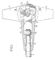
- the blades 1 and 2 of the propeller are articulated relative to the propeller shaft 3 around a transverse axis 4 cooperating with a nozzle 3a carried by this propeller shaft 3.
- This tip can be arranged to constitute a propeller hub.
- the end piece 3a of the propeller shaft 3 has, at its end, an axial slot 5 in which the two blade feet 1a and 2a of the two blades 1 and 2 are housed respectively.
- a synchronization mechanism is provided between each of the two blades 1 and 2 to avoid any asymmetry of the propeller in the event that one of its two branches remains trapped between its rest position and its active position.
- This synchronization mechanism 6 is constituted by a connecting piece 7 slidably mounted axially in the end piece 3a of the propeller shaft 3.
- This connecting piece 7 cooperates with each of the blades 1 and 2 of the propeller, respectively by a connection to pin 8 and groove 9 in the case of blade 1, and to pin 10 and groove 11 in terms of blade 2.
- This connecting piece 7 has a narrowed portion 7a guided in a correspondingly shaped housing 12 formed in the end piece 3a of the propeller shaft 3 beyond the slot 5 presented by said end piece.
- This connecting piece 7 has a wide portion 7b located between the two blade feet 1 and 2a .
- This wide part 7b comprises the two grooves 9 and 11 with which the pins 8 and 10 cooperate respectively.
- transverse axis 4 extend through the parts of the end piece 3 a of the propeller shaft 3 located on either side of the slot 5, through the two blade feet 1a and 2a of the blades 1 and 2, as well as through the connecting piece 7.
- this connecting piece is provided with a light 13 axially elongated surrounding the transverse axis 4.
- the end piece 3a of the propeller shaft 3 is made integral with the latter by a conical fitting 14 and a nut 15.
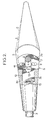
- the blades 1 and 2 of the propeller are arranged so as to be contiguous when they occupy their rest position (fig. 2).
Landscapes
- Chemical & Material Sciences (AREA)
- Engineering & Computer Science (AREA)
- Combustion & Propulsion (AREA)
- Mechanical Engineering (AREA)
- Ocean & Marine Engineering (AREA)
- Structures Of Non-Positive Displacement Pumps (AREA)
- Mixers Of The Rotary Stirring Type (AREA)
Claims (7)
Applications Claiming Priority (2)
| Application Number | Priority Date | Filing Date | Title |
|---|---|---|---|
| FR7831593 | 1978-11-08 | ||
| FR7831593A FR2440869A1 (fr) | 1978-11-08 | 1978-11-08 | Perfectionnements apportes aux helices marines a pales repliables |
Publications (2)
| Publication Number | Publication Date |
|---|---|
| EP0011552A1 EP0011552A1 (de) | 1980-05-28 |
| EP0011552B1 true EP0011552B1 (de) | 1983-10-19 |
Family
ID=9214614
Family Applications (1)
| Application Number | Title | Priority Date | Filing Date |
|---|---|---|---|
| EP19790400834 Expired EP0011552B1 (de) | 1978-11-08 | 1979-11-08 | Schiffsschraube mit zusammenfaltbaren Blättern |
Country Status (3)
| Country | Link |
|---|---|
| EP (1) | EP0011552B1 (de) |
| DE (1) | DE2966338D1 (de) |
| FR (1) | FR2440869A1 (de) |
Cited By (1)
| Publication number | Priority date | Publication date | Assignee | Title |
|---|---|---|---|---|
| US6972956B2 (en) | 2003-01-16 | 2005-12-06 | Hewlett-Packard Development Company, L.P. | Collapsible fan and system and method incorporating same |
Family Cites Families (3)
| Publication number | Priority date | Publication date | Assignee | Title |
|---|---|---|---|---|
| DE411631C (de) * | 1924-06-13 | 1925-03-28 | Hellmuth Hirth | Hilfsluftschraube fuer Segelflugzeuge |
| DE712934C (de) * | 1936-07-01 | 1941-10-29 | Hermann Dorner Dipl Ing | Zweifluegelige Luftschraube mit in die Schraubenumlaufachse schwenkbaren Fluegelblaettern |
| US2500382A (en) * | 1945-07-20 | 1950-03-14 | Elton H Rowley | Folding propeller |
-
1978
- 1978-11-08 FR FR7831593A patent/FR2440869A1/fr active Granted
-
1979
- 1979-11-08 DE DE7979400834T patent/DE2966338D1/de not_active Expired
- 1979-11-08 EP EP19790400834 patent/EP0011552B1/de not_active Expired
Cited By (1)
| Publication number | Priority date | Publication date | Assignee | Title |
|---|---|---|---|---|
| US6972956B2 (en) | 2003-01-16 | 2005-12-06 | Hewlett-Packard Development Company, L.P. | Collapsible fan and system and method incorporating same |
Also Published As
| Publication number | Publication date |
|---|---|
| DE2966338D1 (en) | 1983-11-24 |
| EP0011552A1 (de) | 1980-05-28 |
| FR2440869B1 (de) | 1981-12-31 |
| FR2440869A1 (fr) | 1980-06-06 |
Similar Documents
| Publication | Publication Date | Title |
|---|---|---|
| EP0357494B1 (de) | Schubumkehrvorrichtung mit Hilfsklappen für einen Strahlmotor | |
| FR2612249A1 (fr) | Aubage mobile pour turbines a vapeur | |
| EP0011582B1 (de) | Verbesserung an Systemen zum Aufrollen eines Segels | |
| FR2835562A1 (fr) | Agencement de pivotement d'aube de stator dans une turbomachine | |
| CA2470089C (fr) | Dispositif de guidage d'une aube a angle de calage variable | |
| CA2472876C (fr) | Verrouillage des capots de nacelle d'un turboreacteur | |
| FR2473462A1 (fr) | Helice de bateau pliante | |
| EP0011552B1 (de) | Schiffsschraube mit zusammenfaltbaren Blättern | |
| EP2295928B1 (de) | Vorrichtung zum Öffnen und Verriegeln eines Canard-Flügels | |
| EP0428480B1 (de) | Sicherheitsbindung mit einer Platte | |
| EP1057954B1 (de) | Elektromagnetisches Sicherheitsschloss | |
| EP1535119B1 (de) | Armbanduhr | |
| WO2006063781A1 (fr) | Agencement de liaison debrayable d’un bras d’essuie glace sur un arbre moteur | |
| FR2607107A1 (fr) | Rotor d'helicoptere | |
| FR2573489A1 (fr) | Pompe electrique pour liquide | |
| FR2571021A1 (fr) | Dispositif pour la commande automatique d'un compensateur aerodynamique associe a une surface aerodynamique de commande d'un aeronef | |
| EP4257004B1 (de) | Armbandverschluss | |
| FR2568131A1 (fr) | Broche a glace | |
| FR2765549A1 (fr) | Dispositif de stabilisation pour bateau a voile | |
| EP3650953B1 (de) | Uhrmechanismus, der einen stern und eine sperrfeder umfasst | |
| CA2789462A1 (fr) | Turbopropulseur muni d'un dispositif d'orientation de pales | |
| FR2951397A1 (fr) | Couteau d'ebavurage | |
| FR3066174B1 (fr) | Pedalo a assistance electrique, muni d'un dispositif de relevage / d'immersion de son helice de propulsion | |
| CH719582A2 (fr) | Fermoir de bracelet. | |
| FR2797946A1 (fr) | Dispositif de montage d'un appendice rigide sur un engin apte a etre lance depuis le tube, et engin correspondant |
Legal Events
| Date | Code | Title | Description |
|---|---|---|---|
| PUAI | Public reference made under article 153(3) epc to a published international application that has entered the european phase |
Free format text: ORIGINAL CODE: 0009012 |
|
| AK | Designated contracting states |
Designated state(s): DE GB IT NL SE |
|
| 17P | Request for examination filed |
Effective date: 19800423 |
|
| ITF | It: translation for a ep patent filed | ||
| GRAA | (expected) grant |
Free format text: ORIGINAL CODE: 0009210 |
|
| RAP1 | Party data changed (applicant data changed or rights of an application transferred) |
Owner name: FRANCE HELICES |
|
| AK | Designated contracting states |
Designated state(s): DE GB IT NL SE |
|
| REF | Corresponds to: |
Ref document number: 2966338 Country of ref document: DE Date of ref document: 19831124 |
|
| PLBE | No opposition filed within time limit |
Free format text: ORIGINAL CODE: 0009261 |
|
| STAA | Information on the status of an ep patent application or granted ep patent |
Free format text: STATUS: NO OPPOSITION FILED WITHIN TIME LIMIT |
|
| PGFP | Annual fee paid to national office [announced via postgrant information from national office to epo] |
Ref country code: DE Payment date: 19840921 Year of fee payment: 6 |
|
| PGFP | Annual fee paid to national office [announced via postgrant information from national office to epo] |
Ref country code: SE Payment date: 19840930 Year of fee payment: 6 |
|
| 26N | No opposition filed | ||
| PGFP | Annual fee paid to national office [announced via postgrant information from national office to epo] |
Ref country code: NL Payment date: 19851130 Year of fee payment: 7 |
|
| PG25 | Lapsed in a contracting state [announced via postgrant information from national office to epo] |
Ref country code: SE Effective date: 19861109 |
|
| PG25 | Lapsed in a contracting state [announced via postgrant information from national office to epo] |
Ref country code: NL Effective date: 19870601 |
|
| NLV4 | Nl: lapsed or anulled due to non-payment of the annual fee | ||
| GBPC | Gb: european patent ceased through non-payment of renewal fee | ||
| PG25 | Lapsed in a contracting state [announced via postgrant information from national office to epo] |
Ref country code: DE Effective date: 19870801 |
|
| PG25 | Lapsed in a contracting state [announced via postgrant information from national office to epo] |
Ref country code: GB Effective date: 19881118 |
|
| EUG | Se: european patent has lapsed |
Ref document number: 79400834.2 Effective date: 19870812 |