EP0011495B2 - Méthode et appareil pour commander la rotation d'un disque d'enregistrement d'information - Google Patents
Méthode et appareil pour commander la rotation d'un disque d'enregistrement d'information Download PDFInfo
- Publication number
- EP0011495B2 EP0011495B2 EP79302594A EP79302594A EP0011495B2 EP 0011495 B2 EP0011495 B2 EP 0011495B2 EP 79302594 A EP79302594 A EP 79302594A EP 79302594 A EP79302594 A EP 79302594A EP 0011495 B2 EP0011495 B2 EP 0011495B2
- Authority
- EP
- European Patent Office
- Prior art keywords
- disc
- transducer
- information
- velocity
- signal
- Prior art date
- Legal status (The legal status is an assumption and is not a legal conclusion. Google has not performed a legal analysis and makes no representation as to the accuracy of the status listed.)
- Expired
Links
Images
Classifications
-
- G—PHYSICS
- G11—INFORMATION STORAGE
- G11B—INFORMATION STORAGE BASED ON RELATIVE MOVEMENT BETWEEN RECORD CARRIER AND TRANSDUCER
- G11B19/00—Driving, starting, stopping record carriers not specifically of filamentary or web form, or of supports therefor; Control thereof; Control of operating function ; Driving both disc and head
- G11B19/20—Driving; Starting; Stopping; Control thereof
- G11B19/24—Arrangements for providing constant relative speed between record carrier and head
Definitions
- This invention relates to methods and apparatus for rotating an information disc relative to a radially movable transducer.
- IBM's French Specification No. 2 208 161 relates to a magnetic disc dictation apparatus in which the speed of rotation of the disc is controlled in dependence upon the radial position of a transducer so that the linear speed of the disc in relation to the transducer as the disc rotates is constant, and that enables the information to be packed on the disc uniformly densely. There is no disclosure about the method of driving the transducer.
- the present invention is, more particularly, concerned with discs and transducers between which there is no direct mechanical coupling between the disc drive and the transducer drive.
- Licentia's German Specification No. 2 029 909 discloses a gramophone record system in which there is mechanical transmission between the disc spindle and the transducer carriage.
- the present application is, more particularly, concerned with the type of drive in which disc rotation drive and transducer carriage drive are only connected electrically.
- Discs for storing large quantities of video information have come into increasing usage in recent years as a result of an increasing need for storage media that provide instantaneous playback, fast random access, and relatively high recording density.
- the information is typically encoded on the disc in the form of an optically readable sequence of light-reflective and light-scattering regions arranged in substantially circular tracks forming a spiral or concentric circular pattern over the information bearing surface of the disc.
- the light-reflective and light-scattering regions are initially formed in the disc using an optical transducer for directing onto the disc a collimated beam of high intensity light that is modulated by the information to be recorded.
- the disc is rotated about its central axis at a substantially constant angular velocity relative to the transducer, while the beam of light is moved radially with respect to the disc at a relatively slow, but constant, velocity.
- Each revolution of the disc thus results in the production of a separate, substantially circular information track.
- the disc is ordinarily rotated at approximately 1800 r.p.m., whereby each information track contains the information for one video frame.
- a typical system for rotating a disc at a constant angular velocity includes an oscillator for producing a reference signal having a prescribed constant frequency, and a servo for locking the angular velocity of the disc onto the frequency of the reference signal.
- the servo typically includes a spindle motor for rotating the disc, an AC tachometer coupled to the motor for producing a signal having a frequency indicative of the angular velocity of the motor and a phase detector for comparing the tachometer signal with the reference signal and producing a control signal proportional to the difference in their respective phase angles.
- This control signal is suitably processed in a compensation circuit for producing a prescribed frequency response for the servo, and, in turn, amplified and coupled to the spindle motor to appropriately control its angular velocity.
- apparatus for rotating an information storage disc in relation to a transducer is characterised by means for producing from a radius signal dependent on the radius of the particular track where the transducer is positioned, an alternating current velocity signal having an instantaneous frequency inversely related to the radius of that track, means for rotating the disc at an angular velocity in synchronism with the frequency of that velocity signal, and means for driving the transducer at a radial velocity controlled by the velocity signal.
- the provision of the radius signal with its instantaneous frequency inversely related to the radius of the track enables the angular velocity of rotation of the disc to be very accurately and substantially instantaneously controlled in accordance with the radius.
- the velocity signal is also used for controlling the radial velocity of the transducer to provide a very efficient electronic coupling between the two drives. What is more the pitch between tracks can be varied substantially instantaneously by a simple electronic operation on the velocity signal. It is then simple to ensure that the tracks are substantially evenly spaced with respect to each other to assist further in getting maximum density of information storage on the disc.
- the invention includes the use of such apparatus to record information tracks on the disc and a method according to the precharacterising part of Claim 6 and controlling the drive by generation of the alternating current velocity signal with its frequency inversely proportional to the radius of the selected track in combination with synchronism with the rotation of the disc with the frequency of that velocity signal and moving the transducer at a radial velocity controlled by the velocity signal.
- the velocity signal produced by the VCO is applied to a spindle motor servo for synchronising the angular velocity of a spindle motor that rotates the disc with instantaneous frequency of the velocity signal, whereby the disc is moved at a substantially constant linear velocity relative to the transducer.
- the velocity signal is coupled to a lens carriage driver for controllably rotating the lead screw, and thereby moving the focusing lens in a radial direction, at a corresponding velocity proportional to the frequency of the velocity signal.
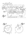
- a servo apparatus for rotating an information storage disc 11 about its central axis 13 at a precisely controlled angular velocity.
- the disc 11 is rotated relative to an optical transducer 15, which operates to record onto the disc information such as a conventional color television signal frequency modulated on a carrier.
- the optical transducer 15 includes means for producing a collimated beam of light (not shown) modulated by the information to be recorded, along with a lens carriage 17, which is controllably movable by a lead screw 19, in a radial direction relative to the disc 11, to direct the light beam onto a selected portion of the disc as the disc is rotated with respect to it.
- This produces a series of substantially circular information tracks (see Figure 2) forming a spiral on the surface of the disc, each track comprising an alternating sequence of light-reflective regions 21 and light-scattering regions 23 ( Figure 3).
- the servo apparatus is shown to include means for producing a velocity signal having a frequency corresponding to the desired angular velocity of the information storage disc 11, along with a spindle motor servo 25, responsive to the velocity signal, for controllably rotating the disc at a corresponding angular velocity.
- the velocity signal has an instantaneous frequency substantially inversely proportional to the radius of the information track being recorded, whereby the track is moved at a substantially constant linear velocity relative to the lens carriage 17 and a uniform information recording density over the entire surface of the disc is achieved.
- the apparatus of Figure 1 further includes a lens carriage driver 37, responsive to the velocity signal, for moving the lens carriage 17 radially relative to the disc 11 at a velocity corresponding to the frequency of the signal.
- a lens carriage driver 37 responsive to the velocity signal, for moving the lens carriage 17 radially relative to the disc 11 at a velocity corresponding to the frequency of the signal.
- FIG. 2 shows, in schematic form, one frame 27 of the video signal, extending over one complete information track near the centre of the disc 11, along with a plurality of consecutive video signal frames 29, 31, 33 and 35 extending over a pair of tracks located near the periphery of the disc, each of these latter frames extending over substantially less than a complete circumference of the disc.
- Figure 3 shows, in enlarged form, the successive light-reflective and light-scattering regions 21 and 23 for a portion of the video signal frame designated 27, along with corresponding regions 21' and 23' for a portion of the frame designated 33. It should be noted that, since all video signal frames recorded on the disc 11 are substantially of equal length, the lengths of the respective light-scattering regions 23 and 23' are, likewise, substantially equal. Thus, a maximum information recording density over the entire surface of the disc 11 can be maintained, and the disc can be used to store a substantially longer- playing video signal than was possibie with conventional constant angular velocity discs.
- the velocity signal which is at a frequency inversely proportional to the radius of the information track being recorded, is produced by a voltage-controlled oscillator (VCO) 39 that is controlled by a control signal received over line 41 from an amplifier circuit 43.
- VCO voltage-controlled oscillator
- This amplifier circuit is appropriately coupled to the lead screw 19, such that as the lens carriage 17 is moved radially, the voltage of the control signal will automatically vary substantially inversely with the radius of the information track being recorded.
- the VCO 39 generates a frequency substantially directly proportional to the voltage of the control signal input, so the frequency of the velocity signal produced by the VCO will likewise vary substantially inversely with the radius of the information track being recorded.
- the amplifier 43 includes a conventional operational amplifier 47, with a fixed resistor 49 coupled between its output and negative input terminals, and with a potentiometer 45 coupled between its negative input terminal and a fixed voltage reference +V REF .
- the potentiometer is mechanically coupled to the lead screw 19 that moves the lens carriage 17 and is adapted to produce a radius signal in the form of an electrical current that varies inversely with the radius of the lens carriage whereby the control signal produced by the amplifier 43 has a voltage likewise inversely proportional to the radius.
- the spindle motor servo 25 operates in a conventional manner to synchronise the angular velocity of the disc 11 with the varying frequency of the velocity signal, whereby the disc is moved at a substantially constant linear velocity relative to the lens carriage 17.
- the servo includes a spindle motor 51 for rotating the disc 11 about its central axis 13, and an AC tachometer 53 mechanically coupled to the spindle motor for producing a tachometer signal having a frequency proportional to its angular velocity.
- the servo further includes a phase detector 55 for comparing the respective phase angles of the tachometer signal, supplied over line 57 from the tachometer, and the velocity signal, supplied on line 59 from the VCO 39, thereby producing a control signal proportional to the phase difference.
- This control signal is transmitted over line 61 to a conventional phase and amplitude compensator 63, and, in turn, over line 65 to an amplifier 67.
- the output of the amplifier is coupled over line 69 to the spindle motor 51 to appropriately control its angular velocity.
- the lens carriage driver 37 operates in a conventional manner to drive the lens carriage 17 in a radial direction relative to the disc 11, at a velocity that corresponds to the frequency of the velocity signal.
- the driver 37 includes a divide-by-N circuit 71 for frequency dividing the velocity signal, supplied on line 59 from the VCO 39, to produce a carriage velocity control signal having a proportionately lower frequency.
- This carriage velocity control signal is transmitted over line 73 to an amplifier 75, and, in turn, over line 77 to a synchronous lens carriage motor 79 for appropriately rotating the lead screw 15 to controllably move the lens carriage in a radial direction relative to the information disc 11.
- the radial velocity of the lens carriage is made to be inversely proportional to the radius of the information track being recorded, and the successive tracks will be substantially equally spaced with respect to each other.
Claims (8)
Priority Applications (1)
| Application Number | Priority Date | Filing Date | Title |
|---|---|---|---|
| AT79302594T ATE9417T1 (de) | 1978-11-16 | 1979-11-15 | Verfahren und apparat zum antreiben einer informationsspeicherplatte. |
Applications Claiming Priority (2)
| Application Number | Priority Date | Filing Date | Title |
|---|---|---|---|
| US05/961,405 US4228326A (en) | 1978-11-16 | 1978-11-16 | System for recording information on a rotatable storage disc, in a substantially uniform recording density |
| US961405 | 1978-11-16 |
Publications (3)
| Publication Number | Publication Date |
|---|---|
| EP0011495A1 EP0011495A1 (fr) | 1980-05-28 |
| EP0011495B1 EP0011495B1 (fr) | 1984-09-12 |
| EP0011495B2 true EP0011495B2 (fr) | 1989-07-12 |
Family
ID=25504432
Family Applications (1)
| Application Number | Title | Priority Date | Filing Date |
|---|---|---|---|
| EP79302594A Expired EP0011495B2 (fr) | 1978-11-16 | 1979-11-15 | Méthode et appareil pour commander la rotation d'un disque d'enregistrement d'information |
Country Status (11)
| Country | Link |
|---|---|
| US (1) | US4228326A (fr) |
| EP (1) | EP0011495B2 (fr) |
| JP (1) | JPS6014421B2 (fr) |
| AT (1) | ATE9417T1 (fr) |
| AU (1) | AU532366B2 (fr) |
| BR (1) | BR7907413A (fr) |
| CA (1) | CA1143061A (fr) |
| DE (1) | DE2967217D1 (fr) |
| HK (1) | HK49586A (fr) |
| MY (1) | MY8700147A (fr) |
| SG (1) | SG14086G (fr) |
Families Citing this family (44)
| Publication number | Priority date | Publication date | Assignee | Title |
|---|---|---|---|---|
| GB2046979B (en) * | 1979-04-17 | 1983-05-18 | Burroughs Corp | Recording and replay apparatus employing rotary media |
| JPS5625264A (en) * | 1979-08-06 | 1981-03-11 | Victor Co Of Japan Ltd | Rotation contrl system for driving motor of recorder for equal line speed information recording medium disk |
| JPS5787371U (fr) * | 1980-11-17 | 1982-05-29 | ||
| JPS57198586A (en) * | 1981-05-28 | 1982-12-06 | Sony Corp | Digital disc reproducing device |
| JPS57198579A (en) * | 1981-05-29 | 1982-12-06 | Sony Corp | Disc reproducing device |
| JPS57208639A (en) * | 1981-06-18 | 1982-12-21 | Toshiba Corp | Recording method of disk |
| JPS5812149A (ja) * | 1981-07-15 | 1983-01-24 | Nippon Columbia Co Ltd | ビデオ・デイスク及びその記録装置 |
| JPS5819767A (ja) * | 1981-07-29 | 1983-02-04 | Nec Home Electronics Ltd | 回転記録媒体の等線速度制御装置 |
| JPS58101358U (ja) * | 1981-12-29 | 1983-07-09 | 日本圧電気株式会社 | 光学式情報読取装置 |
| JPS58175109A (ja) * | 1982-04-07 | 1983-10-14 | Pioneer Video Kk | 円盤状記録媒体の記録方式 |
| JPS59127271A (ja) * | 1983-01-07 | 1984-07-23 | Canon Inc | トランスデユ−サの送り装置 |
| JPS6070563A (ja) * | 1983-09-27 | 1985-04-22 | Toshiba Corp | 高密度螺旋描画装置 |
| JPS61129778A (ja) * | 1984-11-28 | 1986-06-17 | Pioneer Electronic Corp | デイスク再生方式 |
| JPS6254868A (ja) * | 1985-09-03 | 1987-03-10 | Victor Co Of Japan Ltd | 回転記録媒体の回転数制御装置 |
| JPH0666940B2 (ja) * | 1985-12-20 | 1994-08-24 | ソニー株式会社 | ビデオデイスク再生装置 |
| JP2630375B2 (ja) * | 1986-02-28 | 1997-07-16 | パイオニア株式会社 | アドレス探索機能を有する情報再生装置 |
| GB8906353D0 (en) * | 1989-03-20 | 1989-05-04 | Dewar Productions Inc | Semi-timing optic lathe |
| US6141300A (en) * | 1989-06-20 | 2000-10-31 | Discovision Associates | Optical actuator including lens assembly with optical axis having symmetric suspensory forces acting thereon and optical disc system including same |
| US5265079A (en) | 1991-02-15 | 1993-11-23 | Applied Magnetics Corporation | Seek actuator for optical recording |
| US5182741A (en) * | 1989-08-25 | 1993-01-26 | Sharp Kabushiki Kaisha | Optical disk recording/reproducing device utilizing a constant angular velocity method with a constant linear velocity formatted optical disk |
| US5729511A (en) * | 1991-02-15 | 1998-03-17 | Discovision Associates | Optical disc system having servo motor and servo error detection assembly operated relative to monitored quad sum signal |
| US5808980A (en) * | 1991-02-15 | 1998-09-15 | Discovision Associates | Seek actuator for optical recording |
| US5677899A (en) * | 1991-02-15 | 1997-10-14 | Discovision Associates | Method for moving carriage assembly from initial position to target position relative to storage medium |
| US6069857A (en) * | 1991-02-15 | 2000-05-30 | Discovision Associates | Optical disc system having improved circuitry for performing blank sector check on readable disc |
| US6236625B1 (en) | 1991-02-15 | 2001-05-22 | Discovision Associates | Optical disc system having current monitoring circuit with controller for laser driver and method for operating same |
| SG41937A1 (en) | 1991-12-23 | 2002-02-19 | Nimbus Comm Internat Ltd | A disk recording system and a method of controlling the rotation of a turntable in such a disk recording system |
| AU694947B2 (en) * | 1993-02-02 | 1998-08-06 | Nimbus Communications International Limited | A disk recording system |
| US5590102A (en) * | 1995-01-12 | 1996-12-31 | Discovision Associates | Recording informatioin on an optical disc without using pre-manufactured tracks |
| US5748578A (en) * | 1995-01-25 | 1998-05-05 | Discovision Associates | Colpitts type oscillator having reduced ringing and improved optical disc system utilizing same |
| US5920539A (en) * | 1995-01-25 | 1999-07-06 | Discovision Associates | Apparatus and method for suppression of electromagnetic emissions having a groove on an external surface for passing an electrical conductor |
| US6091684A (en) * | 1995-01-25 | 2000-07-18 | Discovision Associates | Optical disc system and method for changing the rotational rate of an information storage medium |
| US6434087B1 (en) | 1995-01-25 | 2002-08-13 | Discovision Associates | Optical disc system and method for controlling bias coil and light source to process information on a storage medium |
| US5978329A (en) * | 1995-06-07 | 1999-11-02 | Discovision Associates | Technique for closed loop servo operation in optical disc tracking control |
| ATE201277T1 (de) * | 1995-12-06 | 2001-06-15 | Discovision Ass | Gerät und verfahren zum regeln der fokussierung |
| US5787292A (en) * | 1996-04-01 | 1998-07-28 | International Business Machines Corporation | Power saving method and apparatus for use in multiple frequency zone drives |
| US5689485A (en) * | 1996-04-01 | 1997-11-18 | Discovision Associates | Tracking control apparatus and method |
| US5808990A (en) * | 1996-12-17 | 1998-09-15 | Cinram, Inc. | Method and apparatus for controlling the linear velocity between an optical head and a rotation disk |
| US6768709B2 (en) | 2000-02-23 | 2004-07-27 | Doug Carson & Associates, Inc. | Hiding digital data in a digital audio or video carrier signal |
| KR100379750B1 (ko) * | 2000-06-30 | 2003-04-16 | 주승용 | 골프용 티이의 구조 |
| US7568081B2 (en) * | 2000-11-15 | 2009-07-28 | Doug Carson & Associates, Inc. | Authenticating a data storage medium using predetermined inter-sector relationships |
| US6477124B2 (en) | 2000-11-15 | 2002-11-05 | Doug Carson & Associates, Inc. | Varying the rate at which data appear on an optical disc rotated at a constant linear velocity to prevent unauthorized duplication of the disc |
| JP2004265491A (ja) * | 2003-02-28 | 2004-09-24 | Matsushita Electric Ind Co Ltd | 情報記録媒体の回転速度制御装置 |
| US7522481B2 (en) * | 2004-10-28 | 2009-04-21 | Koninklijke Philips Electronics N.V. | Disc drive mechanism and method of operation therefor |
| US20060250977A1 (en) * | 2005-05-04 | 2006-11-09 | International Business Machines Corporation | Method and apparatus for determining data center resource availablilty using multiple time domain segments |
Family Cites Families (11)
| Publication number | Priority date | Publication date | Assignee | Title |
|---|---|---|---|---|
| US2113226A (en) * | 1935-05-08 | 1938-04-05 | Rca Corp | Sound recording and reproducing system |
| US2901737A (en) * | 1955-11-01 | 1959-08-25 | Sperry Rand Corp | Disk recording compensating devices |
| DE1562038B2 (de) * | 1968-02-13 | 1971-05-13 | Telefunken Patentverwertungsgesell schaft mbH, 790OUIm | System zur aufzeichnung und abtastung von bildsignalen und der bildwechselfrequenz entsprechenden impulsen unter ver wendung eines plattenfoermigen aufzeichnungstraegers |
| JPS4875002A (fr) * | 1972-01-05 | 1973-10-09 | ||
| DE2257817A1 (de) * | 1972-11-25 | 1974-05-30 | Hubertus Wentzell | Aufzeichnungs- und wiedergabeverfahren fuer platten-informationstraeger |
| US3826965A (en) * | 1972-11-29 | 1974-07-30 | Ibm | Constant tangential velocity motor control for a disc recording system |
| JPS5841710B2 (ja) * | 1973-03-16 | 1983-09-13 | ソニー株式会社 | ジヨウホウシンゴウキロクホウホウ |
| DE2521821A1 (de) * | 1975-05-16 | 1976-11-25 | Bosch Gmbh Robert | Videoplattengeraet |
| US4079942A (en) * | 1975-09-11 | 1978-03-21 | Edward A. Jazlowiecki | Method of and apparatus for controlling turntable speed |
| GB1572346A (en) * | 1976-03-19 | 1980-07-30 | Rca Corp | Velocity and phase control for a disc recording and reproducing apparatus |
| DE2811761A1 (de) * | 1978-03-17 | 1979-09-20 | Wilhelm Dr Ing Lepper | Verfahren zur aufnahme und wiedergabe von schallaufzeichnungen fuer schallplatten und einrichtung zur durchfuehrung des verfahrens |
-
1978
- 1978-11-16 US US05/961,405 patent/US4228326A/en not_active Expired - Lifetime
-
1979
- 1979-11-14 BR BR7907413A patent/BR7907413A/pt not_active IP Right Cessation
- 1979-11-15 EP EP79302594A patent/EP0011495B2/fr not_active Expired
- 1979-11-15 DE DE7979302594T patent/DE2967217D1/de not_active Expired
- 1979-11-15 CA CA000339916A patent/CA1143061A/fr not_active Expired
- 1979-11-15 AU AU52844/79A patent/AU532366B2/en not_active Expired
- 1979-11-15 AT AT79302594T patent/ATE9417T1/de not_active IP Right Cessation
- 1979-11-16 JP JP54147823A patent/JPS6014421B2/ja not_active Expired
-
1986
- 1986-02-15 SG SG140/86A patent/SG14086G/en unknown
- 1986-07-03 HK HK495/86A patent/HK49586A/xx not_active IP Right Cessation
-
1987
- 1987-12-30 MY MY147/87A patent/MY8700147A/xx unknown
Also Published As
| Publication number | Publication date |
|---|---|
| AU532366B2 (en) | 1983-09-29 |
| EP0011495B1 (fr) | 1984-09-12 |
| HK49586A (en) | 1986-07-11 |
| BR7907413A (pt) | 1980-07-22 |
| US4228326A (en) | 1980-10-14 |
| ATE9417T1 (de) | 1984-09-15 |
| SG14086G (en) | 1990-08-17 |
| CA1143061A (fr) | 1983-03-15 |
| EP0011495A1 (fr) | 1980-05-28 |
| MY8700147A (en) | 1987-12-31 |
| JPS6014421B2 (ja) | 1985-04-13 |
| JPS55101162A (en) | 1980-08-01 |
| DE2967217D1 (en) | 1984-10-18 |
| AU5284479A (en) | 1980-05-22 |
Similar Documents
| Publication | Publication Date | Title |
|---|---|---|
| EP0011495B2 (fr) | Méthode et appareil pour commander la rotation d'un disque d'enregistrement d'information | |
| CA1124395A (fr) | Methode et appareil digitataux pour faire tourner un disque porteur d'information | |
| US4271334A (en) | Apparatus for correcting for temperature-induced tracking errors in a system for recovering information from a recording disc | |
| EP0080256B1 (fr) | Appareil d'enregistrement et de reproduction d'information | |
| EP0035803B1 (fr) | Servo-système pour un arbre moteur d'une mémoire à disques | |
| US4390977A (en) | Apparatus for maintaining rotational speed in disk reproducing device | |
| US4530083A (en) | Rotatable memory disk apparatus | |
| JPS6010459A (ja) | デイスク装置 | |
| JPH06101199B2 (ja) | デイスク装置 | |
| US3361873A (en) | Disc recording system | |
| EP0240678B1 (fr) | Commande de vitesse de rotation par modulation de largeur d'impulsion | |
| JPS6011374B2 (ja) | 情報再生方法及びその装置 | |
| JPH0210482B2 (fr) | ||
| US4814897A (en) | Method and system for retrieving video information from a non-CAV type recording disk in special reproduction modes | |
| JP2544585B2 (ja) | 光ディスクプレ―ヤ | |
| US4897827A (en) | Video disc player with rapid track access means | |
| US3391255A (en) | Transducing system | |
| US4351044A (en) | Recording system using disk-shaped recording medium | |
| US4005260A (en) | Device for reading a disk-shaped record carrier with time base correction | |
| US5063552A (en) | Optical disk apparatus with data transfer rate and rotational speed variable by annular zones | |
| US4719611A (en) | Apparatus for controlling a recording operation of an optical information recording apparatus | |
| JPS59186178A (ja) | Clvデイスクのランダムアクセス装置 | |
| JP2630375B2 (ja) | アドレス探索機能を有する情報再生装置 | |
| US4086520A (en) | Speed and phase control system | |
| JPH0468826B2 (fr) |
Legal Events
| Date | Code | Title | Description |
|---|---|---|---|
| PUAI | Public reference made under article 153(3) epc to a published international application that has entered the european phase |
Free format text: ORIGINAL CODE: 0009012 |
|
| AK | Designated contracting states |
Designated state(s): AT BE CH DE FR GB IT LU NL SE |
|
| 17P | Request for examination filed |
Effective date: 19801007 |
|
| RAP1 | Party data changed (applicant data changed or rights of an application transferred) |
Owner name: DISCOVISION ASSOCIATES |
|
| ITF | It: translation for a ep patent filed |
Owner name: SOCIETA' ITALIANA BREVETTI S.P.A. |
|
| GRAA | (expected) grant |
Free format text: ORIGINAL CODE: 0009210 |
|
| AK | Designated contracting states |
Designated state(s): AT BE CH DE FR GB IT LU NL SE |
|
| REF | Corresponds to: |
Ref document number: 9417 Country of ref document: AT Date of ref document: 19840915 Kind code of ref document: T |
|
| REF | Corresponds to: |
Ref document number: 2967217 Country of ref document: DE Date of ref document: 19841018 |
|
| ET | Fr: translation filed | ||
| PLBI | Opposition filed |
Free format text: ORIGINAL CODE: 0009260 |
|
| 26 | Opposition filed |
Opponent name: N.V. PHILIPS' GLOEILAMPENFABRIEKEN Effective date: 19850612 |
|
| NLR1 | Nl: opposition has been filed with the epo |
Opponent name: N.V. PHILIPS' GLOEILAMPENFABRIEKEN |
|
| RAP2 | Party data changed (patent owner data changed or rights of a patent transferred) |
Owner name: DISCOVISION ASSOCIATES |
|
| PUAH | Patent maintained in amended form |
Free format text: ORIGINAL CODE: 0009272 |
|
| STAA | Information on the status of an ep patent application or granted ep patent |
Free format text: STATUS: PATENT MAINTAINED AS AMENDED |
|
| ITF | It: translation for a ep patent filed |
Owner name: SOCIETA' ITALIANA BREVETTI S.P.A. |
|
| 27A | Patent maintained in amended form |
Effective date: 19890712 |
|
| AK | Designated contracting states |
Kind code of ref document: B2 Designated state(s): AT BE CH DE FR GB IT LU NL SE |
|
| NLR2 | Nl: decision of opposition | ||
| NLR3 | Nl: receipt of modified translations in the netherlands language after an opposition procedure | ||
| ET3 | Fr: translation filed ** decision concerning opposition | ||
| ITTA | It: last paid annual fee | ||
| EPTA | Lu: last paid annual fee | ||
| EAL | Se: european patent in force in sweden |
Ref document number: 79302594.1 |
|
| PGFP | Annual fee paid to national office [announced via postgrant information from national office to epo] |
Ref country code: FR Payment date: 19981020 Year of fee payment: 20 |
|
| PGFP | Annual fee paid to national office [announced via postgrant information from national office to epo] |
Ref country code: SE Payment date: 19981021 Year of fee payment: 20 Ref country code: GB Payment date: 19981021 Year of fee payment: 20 |
|
| PGFP | Annual fee paid to national office [announced via postgrant information from national office to epo] |
Ref country code: DE Payment date: 19981022 Year of fee payment: 20 Ref country code: AT Payment date: 19981022 Year of fee payment: 20 |
|
| PGFP | Annual fee paid to national office [announced via postgrant information from national office to epo] |
Ref country code: NL Payment date: 19981026 Year of fee payment: 20 |
|
| PGFP | Annual fee paid to national office [announced via postgrant information from national office to epo] |
Ref country code: CH Payment date: 19981027 Year of fee payment: 20 |
|
| PGFP | Annual fee paid to national office [announced via postgrant information from national office to epo] |
Ref country code: LU Payment date: 19981105 Year of fee payment: 20 |
|
| PGFP | Annual fee paid to national office [announced via postgrant information from national office to epo] |
Ref country code: BE Payment date: 19981117 Year of fee payment: 20 |
|
| BE20 | Be: patent expired |
Free format text: 19991115 *DISCOVISION ASSOCIATES |
|
| REG | Reference to a national code |
Ref country code: GB Ref legal event code: 7722 Ref country code: GB Ref legal event code: 727G Free format text: ORDERS STAYED PENDING APPEAL |
|
| PG25 | Lapsed in a contracting state [announced via postgrant information from national office to epo] |
Ref country code: GB Free format text: LAPSE BECAUSE OF EXPIRATION OF PROTECTION Effective date: 19991114 Ref country code: CH Free format text: LAPSE BECAUSE OF EXPIRATION OF PROTECTION Effective date: 19991114 |
|
| PG25 | Lapsed in a contracting state [announced via postgrant information from national office to epo] |
Ref country code: NL Free format text: LAPSE BECAUSE OF EXPIRATION OF PROTECTION Effective date: 19991115 Ref country code: LU Free format text: LAPSE BECAUSE OF EXPIRATION OF PROTECTION Effective date: 19991115 Ref country code: AT Free format text: LAPSE BECAUSE OF EXPIRATION OF PROTECTION Effective date: 19991115 |
|
| PG25 | Lapsed in a contracting state [announced via postgrant information from national office to epo] |
Ref country code: SE Free format text: LAPSE BECAUSE OF NON-PAYMENT OF DUE FEES Effective date: 19991116 |
|
| REG | Reference to a national code |
Ref country code: GB Ref legal event code: PE20 Effective date: 19991114 |
|
| REG | Reference to a national code |
Ref country code: CH Ref legal event code: PL |
|
| NLV7 | Nl: ceased due to reaching the maximum lifetime of a patent |
Effective date: 19991115 |
|
| EUG | Se: european patent has lapsed |
Ref document number: 79302594.1 |
|
| REG | Reference to a national code |
Ref country code: GB Ref legal event code: 772R |