EP0010747B1 - Apparatus for filtering solids-containing liquids - Google Patents
Apparatus for filtering solids-containing liquids Download PDFInfo
- Publication number
- EP0010747B1 EP0010747B1 EP79104163A EP79104163A EP0010747B1 EP 0010747 B1 EP0010747 B1 EP 0010747B1 EP 79104163 A EP79104163 A EP 79104163A EP 79104163 A EP79104163 A EP 79104163A EP 0010747 B1 EP0010747 B1 EP 0010747B1
- Authority
- EP
- European Patent Office
- Prior art keywords
- filter
- filter band
- cleaning
- band
- region
- Prior art date
- Legal status (The legal status is an assumption and is not a legal conclusion. Google has not performed a legal analysis and makes no representation as to the accuracy of the status listed.)
- Expired
Links
- 239000007788 liquid Substances 0.000 title claims abstract description 14
- 239000007787 solid Substances 0.000 title claims abstract description 14
- 238000001914 filtration Methods 0.000 title claims abstract description 8
- 238000004140 cleaning Methods 0.000 claims abstract description 41
- XLYOFNOQVPJJNP-UHFFFAOYSA-N water Substances O XLYOFNOQVPJJNP-UHFFFAOYSA-N 0.000 claims abstract description 11
- 241000219310 Beta vulgaris subsp. vulgaris Species 0.000 claims abstract description 7
- 235000021536 Sugar beet Nutrition 0.000 claims abstract description 7
- 238000007873 sieving Methods 0.000 claims abstract 2
- 238000007789 sealing Methods 0.000 claims description 6
- 239000013013 elastic material Substances 0.000 claims description 2
- 230000001174 ascending effect Effects 0.000 claims 1
- 238000010276 construction Methods 0.000 description 6
- 239000004744 fabric Substances 0.000 description 4
- CZMRCDWAGMRECN-UHFFFAOYSA-N Rohrzucker Natural products OCC1OC(CO)(OC2OC(CO)C(O)C(O)C2O)C(O)C1O CZMRCDWAGMRECN-UHFFFAOYSA-N 0.000 description 3
- 230000000694 effects Effects 0.000 description 3
- 239000012065 filter cake Substances 0.000 description 3
- 239000000463 material Substances 0.000 description 3
- 239000002245 particle Substances 0.000 description 3
- 239000004576 sand Substances 0.000 description 3
- 238000005406 washing Methods 0.000 description 3
- 235000016068 Berberis vulgaris Nutrition 0.000 description 2
- 241000335053 Beta vulgaris Species 0.000 description 2
- 230000015572 biosynthetic process Effects 0.000 description 2
- 239000000470 constituent Substances 0.000 description 2
- 230000000284 resting effect Effects 0.000 description 2
- 239000000126 substance Substances 0.000 description 2
- 241000196324 Embryophyta Species 0.000 description 1
- 230000009471 action Effects 0.000 description 1
- 230000009172 bursting Effects 0.000 description 1
- 238000011161 development Methods 0.000 description 1
- 230000018109 developmental process Effects 0.000 description 1
- 230000006872 improvement Effects 0.000 description 1
- 230000003993 interaction Effects 0.000 description 1
- 230000007246 mechanism Effects 0.000 description 1
- 238000000034 method Methods 0.000 description 1
- 230000008569 process Effects 0.000 description 1
- 238000000746 purification Methods 0.000 description 1
- 238000007665 sagging Methods 0.000 description 1
- 238000010408 sweeping Methods 0.000 description 1
Images


Classifications
-
- B—PERFORMING OPERATIONS; TRANSPORTING
- B01—PHYSICAL OR CHEMICAL PROCESSES OR APPARATUS IN GENERAL
- B01D—SEPARATION
- B01D33/00—Filters with filtering elements which move during the filtering operation
- B01D33/04—Filters with filtering elements which move during the filtering operation with filtering bands or the like supported on cylinders which are impervious for filtering
-
- B—PERFORMING OPERATIONS; TRANSPORTING
- B01—PHYSICAL OR CHEMICAL PROCESSES OR APPARATUS IN GENERAL
- B01D—SEPARATION
- B01D33/00—Filters with filtering elements which move during the filtering operation
- B01D33/056—Construction of filtering bands or supporting belts, e.g. devices for centering, mounting or sealing the filtering bands or the supporting belts
Definitions
- the invention relates to a device for filtering liquids containing solids, in particular for filtering water-flush flow for the transport of sugar beets in a beet sugar factory, with an endless, rotating filter belt with sieve or filter openings, the upper strand of which serves as a sieve surface, and with a the filter belt cleaning station located downstream of the upper run, in the area of which the filter belt can be stretched by widening the sieve or filter openings.
- Beet sugar factories are mostly set up so that By J '' ie agriculture are promoted delivered sugar beet ⁇ nem system of channels by a wassiden Schwemmstrom on the Betreospond the factory.
- the sugar beet reached by all foreign bodies, so beet leaves, weeds, sand, stones etc.
- the unwanted constituents and foreign bodies are separated from the beet during transport and removed from the sweeping stream in appropriate stations widely clarified that it can be returned to the wash stream to form a closed circuit.
- the clarifier as the final stage of water purification is usually preceded by a sand trap and a filter.
- the latter is used to separate particularly fine solids, especially organic components, from the water.
- the present invention is concerned with the improvement of the latter device.
- the main aim is to increase the efficiency of the filter device in the simplest possible way by avoiding the sealing of the filter openings of the filter belt.
- GB-A-532750 can be removed, in order to improve the cleaning and thus the filter performance of the filter belt, to stretch it in the area of the cleaning station by widening the sieve or filter openings.
- this is done in such a way that the filter belt is stretched in the longitudinal direction by stretching rollers which are driven much faster than the other deflecting rollers.
- the screen or filter openings are widened or stretched between two pairs of stretching rollers in the conveying direction of the filter belt.
- the filter belt is sprinkled with a cleaning liquid in the cleaning station.
- GB-A-532750 also proposes to simultaneously stretch the filter belt in the cleaning station in the transverse direction by means of a tensioning frame, so that in the cleaning station the sieve or filter openings are widened both in the longitudinal and in the transverse direction of the filter belt .
- a disadvantage of the known construction is that either separate drives or at least one additional gear are required for the stretching rollers. Furthermore, a special clamping frame for the transverse expansion of the filter belt must be provided. The known construction is therefore relatively complex.
- the additional cleaning with a cleaning liquid is also accompanied by a certain effort, since an additional liquid circuit with pumps, catch basins, sieves, filters is required.
- a so-called "cake removal device for drum filters with a running filter cloth is known, in which the filter cloth or filter belt is guided over rollers, one of which has ridges for" the filter cake bursting or flaking off.
- the ridges each have a sinusoidal shape, where they rest in the valley of the sinus curve on the roller jacket of the deflecting roller and move away from the jacket until the upper vertex of the sinus curve is reached.
- the arrangement of the elevations is chosen so that the filter cloth is only stretched at individual points, and that these points “move” over the width of the roller or over the width of a sine curve in the course of one revolution of the deflecting roller.
- DE-B-1 285454 thus conveys the teaching of mounting elevations on a deflecting roller in such a way that the "expansion point moves parallel to the roller axis during one roller revolution and that only in this way can the filter cake be broken into small pieces.
- the present invention is therefore based on the object of providing a filter device of the type mentioned at the outset which, with relatively simple means, permits a higher filter effect due to improved cleaning of the endless filter belt running around.
- the cleaning station contains at least one deflection roller, via which Filter band is guided and which is provided on the outside of its jacket with ribs that stretch the filter band across its entire width in the transverse direction.
- the solution according to the invention is characterized by a conceivably simple, yet highly effective construction. Additional drives for stretching rollers for widening the screen or filter openings in the conveying direction of the filter belt or clamping frames for widening the screen or filter openings transversely to the conveying direction of the filter belt are not required.
- the invention allows. Solution the formation of relatively fine filter openings with the result that a layer of settled solids is constantly formed on the filter belt, which has the effect of an additional filter in the area of the upper run of the liquid. At the same time, however, sealing or clogging of the filter openings is effectively avoided by the measures according to the invention. Additional suction, compressed air or washing facilities are not required.
- the filter device shown here as an exemplary embodiment is primarily intended for use in the operation of a beet sugar factory, that is to say for cleaning or filtering flood water with fine solids, such as sand and organic constituents.
- a filter surface of the device is formed by an endless filter belt 10. According to FIG. 1, this is guided over three deflecting rollers 1.1, 12, 13, which are arranged in the corners of a triangle.
- the filter belt 10 is thereby given an approximately triangular shape in a side view.
- the deflection roller 11 is also designed as a tension roller with a tensioning device 14.
- the drive of the continuously rotating filter belt 10 is effected by the deflection roller 12, which in turn is driven by a motor 15 via a belt drive 16.
- the deflection rollers 11, 12, 13 are otherwise supported in a support frame 17.
- the filter belt 10 is cleaned outside the area of the protruding screen surface.
- the cleaning strands 20 guided between the deflecting rollers 12, 13 are assigned cleaning units to be explained in detail.
- the cleaning strand 20 is guided by the arrangement of the deflecting rollers 12, 13 so that in this area the filter belt 10 is guided somewhat out of the vertical, so that the solids accumulating during the cleaning process can fall down freely.
- the filter band 10 is designed in a special way. It consists of an elastically stretchable material, in particular plastic.
- the filter belt 10 consists of a plurality of webs 21a, 21b, 21c lying side by side in the direction of rotation. These are arranged relative to one another in such a way that there is an overlap 22 between adjacent tracks 21a, 21b.
- Each web 21a, 21b .. in turn in the present case consists of individual rectangular mats 23 of an appropriate size.
- the mats 23 are detachable in the circumferential direction connected, so that each mat 23 can be replaced individually if necessary.
- common, transverse joints 27, 28 are provided for the mats 23 of all webs 21 a, 21 b ..
- the butt and connection points 27, 28 of the mats 23 are formed here by clamping strips 24, 25, which capture the mutually facing edges of successive mats 23 and connect them to one another by positive locking and clamping action.
- a clamping strip 24 or 25 is arranged on both sides of the mats 23. Both terminal strips 24, 25 are gripped and held together by a connecting screw 26 which can be operated from above.
- these are provided with holes 45 on the mutually facing edges in the region of an overlap also formed there. These are pressed with a widening over a holding pin 46 of the terminal strips 24, 25 and thereby fixed or pre-fixed.
- the upper, free end of these holding pins 46 is formed with a barb-like widening 47, by means of which the mats 23 are pressed while the holes 45 are widened.
- two mats 23 with the edges lie one above the other in this area.
- the holding pin 46 is anchored, for example, with a thread in the lower terminal strip 25.
- An internally threaded bore in the holding pin 46 receives the connecting screw 26, whereby the clamping strips 24, 25 are pressed against one another or against the mats 23 while exerting a considerable clamping pressure.
- the terminal strips 24, 25 consist of individual sections, each with a length that corresponds to the width of a track 21a, 21b ..
- the sections of the respective terminal strips 24 in the area of the overlap 22 are provided with an also overlapping joint 27.
- joints 28 of the lower terminal strips 25 are provided.
- the clamping strips 24, 25 which extend in this way over the entire width of the filter belt 10 stabilize the filter belt 10 and at the same time guide in the lateral area.
- support rollers 29 are arranged on the free ends of the clamping strips 24, 25, which protrude beyond the filter belt 10 and are supported on an upright lateral guide rail 30 of the device in the region of the upper strand 18.
- these support rollers 29 are arranged outside the filter area, which is laterally limited by an elastic limitation in the form of a sealing tab 31 resting on the filter belt 10.
- This sealing tab 31 is in turn arranged on a side wall 32 projecting inwards here, which in turn delimits the space or area for receiving the liquid to be cleaned.
- the filter belt 10 can be equipped with relatively small filter openings 33.
- these are rectangular and extend in the longitudinal direction, that is to say in the direction of movement of the filter band 10.
- the filter openings 33 arranged in rows are offset or arranged in a gap with respect to one another.
- a deformation of the filter openings 33 in the sense of FIG. 9 is possible, namely by transverse expansion of the filter belt 10. Any solid particles that may be jammed in the fine filter openings 33 can thereby be removed, particularly in connection with a cleaning unit 35.
- the transverse stretching of the filter belt 10 in the above sense takes place in the region of the deflecting roller 13, which is provided with annularly arranged ribs 34 on its jacket.
- the ribs 34 consist of welded rings made of round material.
- the ribs 34 can be arranged in a helical manner, as a result of which the filter band 10 is stretched or stretched over the width in different areas during the repeating cycles.
- the cross-sectional shape of the filter belt 10 shown in FIG. 7 results in the region of the deflecting roller 13, with the result that the filter openings 33 are widened in the sense of FIG. 9.
- the filter openings 33 can thereby have the smallest width dimensions, for example down to 0.1 mm.
- a cleaning unit 35 assigned to the cleaning strand 20 in the present case comprises a cleaning strip 36 which can be delivered to the cleaning strand 20. This is driven in such a way that it carries out a relative movement to the filter belt 10 such that this cleaning tool knocks or strikes the filter belt 10 is moved up.
- a crank mechanism 37 is provided for the movement of the cleaning bar 36.
- a fixed, elastic scraper 38 Downstream in the direction of movement is a fixed, elastic scraper 38, which also extends over the entire width of the filter belt 10.
- This wiper 38 which is made of elastic material, is constantly in contact with the moving filter belt 10. A certain contact pressure in the area of the widened filter openings 33 pulls out solid particles, particularly threads, etc., which are seated therein.
- the filter surface of the filter belt 10, namely the upper run 18, is accommodated in an upwardly open container which has a greater depth on the inlet side due to the inclined arrangement of the upper run 18.
- the liquid is supplied via an overflow 39.
- the overflow 39 is preceded by a transversely extending collecting trough 40 in which any energy of the inflowing water is destroyed.
- a baffle plate 41 arranged above the collecting trough 40 has the same task.
- the overflow 39 in connection with the side wall 32 and the upper run 18 thus creates a container for holding the liquid to be cleaned, from which the filter surface can be moved continuously by the filter. Band 10 is constantly moved out.
- FIG. 3 shows a detail of the filter belt 10 in the area of the overlaps 22.
- an elastic hold-down 42 above the filter belt 10 is in each case here Area of the overlaps 22 arranged.
- the flap-like or strip-shaped hold-down device 42 is anchored above the filter belt 10 in corresponding holding rails 48 in such a way that the hold-down device 42 deflected in an arc shape by 90 ° rests on the filter belt 10 with a corresponding contact pressure in the region of the overlap 22.
- the relative arrangement and dimensions of the hold-down device 42 are selected such that the free step formed in the area of the overlap 22 is covered.
- the configuration according to FIG. 11 serves the same subject, namely the arrangement of the support rollers 19 along an arc.
- the filter belt 10 is guided in a polygonal manner in the region of the upper run 18.
- the exposed sections of the filter belt 10 are thereby given a higher tension, so that the overlapping edges of the webs 21a, 21b.
- a large-scale container 43 is formed for receiving the cleaned liquid. From this, the water can be discharged via large outlet openings 44 which are preferably arranged on both sides.
- an elastic apron 49 resting on the filter belt 10 is formed, which is designed essentially in the same or similar manner as the sealing tab 31 in the area of the side wall 32.
- the task of this Apron 49 is on the one hand the seal of the “rail container” formed here for holding the liquid to be cleaned on the “valley side” of the filter belt 10.
- the fixed apron 49 which is oriented transversely to the filter belt 10, has the function of a further cleaning element. Any solids still adhering to or on the filter belt 10 in this area are removed here.
- the cleaning elements arranged in a fixed relative position in particular the scraper 38 and the aforementioned apron 49, are in turn permanently freed of the residues collected, namely by the clamping strips 24 arranged as an increase on the filter belt 10. These become corresponding to the length of the mats 23 successively guided past the scraper 38 and the apron 49, with the result that solid parts deposited here are carried along by the terminal strips 24.
Landscapes
- Chemical & Material Sciences (AREA)
- Chemical Kinetics & Catalysis (AREA)
- Filtration Of Liquid (AREA)
Abstract
Description
Die Erfindung betrifft eine Vorrichtung zum Filtern von Feststoffe enthaltenden Flüssigkeiten, insbesondere zum Filtern von Wasser rines Schwemmstroms für den Transport von Zuckerrüben in einer Rübenzuckerfabrik, mit einem endlosen, umlaufenden Filterband mit Sieb- bzw. Filteröffnungen, dessen Obertrum als Siebfläche dient, und mit einer dem Obertrum nachgeordneten Filterband-Reinigungsstation, in deren Bereich das Filterband unter Aufweiten der Sieb- bzw. Filteröffnungen dehnbar ist.The invention relates to a device for filtering liquids containing solids, in particular for filtering water-flush flow for the transport of sugar beets in a beet sugar factory, with an endless, rotating filter belt with sieve or filter openings, the upper strand of which serves as a sieve surface, and with a the filter belt cleaning station located downstream of the upper run, in the area of which the filter belt can be stretched by widening the sieve or filter openings.
Rübenzuckerfabriken sind überwiegend so eingerichtet, daß die durc" 'ie Landwirtschaft angelieferten Zuckerrübe^ nem System von Kanälen durch einen wführenden Schwemmstrom auf dem Betreosgelände der Fabrik gefördert werden. Die Zuckerrüben gelangen mit allen Fremdkörpern, also Rübenblättern, Unkraut, Sand, Steinen etc. in diesen Schwemmstrom. Die unerwünschten Bestandteile und Fremdkörper werden während des Transportes der Zuckerrüben von diesen abgesondert und in entsprechenden Stationen aus dem Schwemmstrom entfernt. Das Wasser des Schwemmstroms wird schließlich - nach Entnahme der zu verarbeitenden Zuckerrüben - einem Klärbecken zügeführt. In diesem wird das Wasser so weit geklärt, daß es unter Bildung eines geschlossenen Kreislaufs in den Schwemmstrom zurückgegeben werden kann.Beet sugar factories are mostly set up so that By J '' ie agriculture are promoted delivered sugar beet ^ nem system of channels by a wführenden Schwemmstrom on the Betreosgelände the factory. The sugar beet reached by all foreign bodies, so beet leaves, weeds, sand, stones etc. The unwanted constituents and foreign bodies are separated from the beet during transport and removed from the sweeping stream in appropriate stations widely clarified that it can be returned to the wash stream to form a closed circuit.
Dem Klärbecken als Endstufe der Wasserreinigung sind gewöhnlich ein Sandfänger und ein Filter vorgeordnet. Letzterer dient der Absonderung von besonders feinen Feststoffanteilen, und zwar vor allem auch organischer Bestandteile, aus dem Wasser.The clarifier as the final stage of water purification is usually preceded by a sand trap and a filter. The latter is used to separate particularly fine solids, especially organic components, from the water.
Mit der Verbesserung der letztgenannten Einrichtung befaßt sich die vorliegende Erfindung. Dabei geht es vornehmlich darum, den Wirkungsgrad der Filtereinrichtung in möglichst einfacher Weise durch Vermeidung des Dichtsetzens der Filteröffnungen des Filterbandes zu erhöhen.The present invention is concerned with the improvement of the latter device. The main aim is to increase the efficiency of the filter device in the simplest possible way by avoiding the sealing of the filter openings of the filter belt.
Der GB-A-532750 kann entnommen werden, zur Verbesserung der Reinigung und damit der Filterleistung des Filterbandes dieses im Bereich der Reinigungsstation unter Aufweiten der Sieb- bzw. Filteröffnungen zu dehnen. Dies erfolgt bei der bekannten Konstruktion derart, daß das Filterband durch gegenüber den übrigen Umlenkwalzen wesentlich schneller angetriebene Streckwalzen in Längsrichtung gedehnt wird. Die Sieb- bzw. Filteröffnungen werden dabei zwischen zwei Streckwalzenpaaren in Förderrichtung des Filterbandes aufgeweitet bzw. gestreckt. Zusätzlich erfolgt in der Reinigungsstation eine Berieselung des Filterbandes mit einer Reinigungsflüssigkeit.GB-A-532750 can be removed, in order to improve the cleaning and thus the filter performance of the filter belt, to stretch it in the area of the cleaning station by widening the sieve or filter openings. In the known construction, this is done in such a way that the filter belt is stretched in the longitudinal direction by stretching rollers which are driven much faster than the other deflecting rollers. The screen or filter openings are widened or stretched between two pairs of stretching rollers in the conveying direction of the filter belt. In addition, the filter belt is sprinkled with a cleaning liquid in the cleaning station.
In der GB-A-532750 ist auch vorgeschlagen, das Filterband in der Reinigungsstation gleichzeitig in Querrichtung mittels eines Spannrahmens zu dehnen, so daß in der Reinigungsstation eine Aufweitung der Sieb- bzw. Filteröffnungen sowohl in Längs- als auch in Querrichtung des Filterbandes erhalten wird.GB-A-532750 also proposes to simultaneously stretch the filter belt in the cleaning station in the transverse direction by means of a tensioning frame, so that in the cleaning station the sieve or filter openings are widened both in the longitudinal and in the transverse direction of the filter belt .
Nachteilig bei der bekannten Konstruktion ist, daß für die Streckwalzen entweder gesonderte Antriebe oder zumindest ein zusätzliches Getriebe erforderlich sind. Ferner muß ein spezieller Spannrahmen für die Querdehnung des Filterbandes vorgesehen werden. Die bekannte Konstruktion ist daher relativ aufwendig.A disadvantage of the known construction is that either separate drives or at least one additional gear are required for the stretching rollers. Furthermore, a special clamping frame for the transverse expansion of the filter belt must be provided. The known construction is therefore relatively complex.
Die zusätzliche Reinigung durch eine Reinigungsflüssigkeit ist ebenfalls von einem gewissen Aufwand begleitet, da ein zusätzlicher Flüssigkeitskreislauf mit Pumpen, Auffangbecken, Sieben, Filter erforderlich ist.The additional cleaning with a cleaning liquid is also accompanied by a certain effort, since an additional liquid circuit with pumps, catch basins, sieves, filters is required.
Aus der DE-B-1 285 454 ist eine sogenannte « Kuchenabnahme-vorrichtung für Trommelfilter mit ablaufendem Filtertuch bekannt, bei der das Filtertuch bzw. Filterband über Walzen geführt ist, von denen eine Erhöhungen zum « Auf- bzw. Abplatzen des Filterkuchens aufweist. Die Erhöhungen haben jeweils einen sinusförmigen Verlauf, wobei sie im Tal der Sinuskurve auf dem Walzenmantel der Umlenkwalze aufliegen und sich bis zum Erreichen des oberen Scheitels der Sinuskurve vom Mantel entfernen. Die Anordnung der Erhöhungen ist dabei so gewählt, daß das Filtertuch immer nur an einzelnen Punkten gedehnt wird, und daß diese Punkte im Verlauf einer Umdrehung der Umlenkwalze über die Breite der Walze bzw. über die Breite einer Sinuskurve « wandert ». Dadurch soll erreicht werden, daß der Filterkuchen nicht mehr parallel zu der Walzenachse aufgerissen wird, sondern daß eine Art Craqueleerisse entsteht. Die DE-B-1 285454 vermittelt also die Lehre, auf einer Umlenkwalze Erhöhungen so anzubringen, daß der « Dehnpunkt während einer Walzenumdrehung parallel zur Walzenachse wandert und daß nur so ein Zerbrechen des Filterkuchens in kleine Stückchen erreichbar ist.From DE-B-1 285 454 a so-called "cake removal device for drum filters with a running filter cloth is known, in which the filter cloth or filter belt is guided over rollers, one of which has ridges for" the filter cake bursting or flaking off. The ridges each have a sinusoidal shape, where they rest in the valley of the sinus curve on the roller jacket of the deflecting roller and move away from the jacket until the upper vertex of the sinus curve is reached. The arrangement of the elevations is chosen so that the filter cloth is only stretched at individual points, and that these points “move” over the width of the roller or over the width of a sine curve in the course of one revolution of the deflecting roller. This is to ensure that the filter cake is no longer torn open parallel to the roller axis, but that a kind of craquelure cracks are created. DE-B-1 285454 thus conveys the teaching of mounting elevations on a deflecting roller in such a way that the "expansion point moves parallel to the roller axis during one roller revolution and that only in this way can the filter cake be broken into small pieces.
Ferner ist auch bei der bekannten Konstruktion gemäß der DE-B-1 285 454 noch eine zusätzliche Reinigung des Filtertuches durch Waschdüsen vorgesehen mit dem bereits erwähnten Nachteil, daß ein zusätzlicher Kreislauf für die Reinigungs- bzw. Waschflüssigkeit mit Pumpe, Filter etc. erforderlich ist. Die bekannte Konstruktion gemäß der DE-B-1 285454 zeichnet sich also ebenfalls durch einen relativ großen Aufwand bei nur mäßigem Wirkungsgrad aus.Furthermore, in the known construction according to DE-B-1 285 454, an additional cleaning of the filter cloth by means of washing nozzles is provided, with the already mentioned disadvantage that an additional circuit for the cleaning or washing liquid with pump, filter etc. is required . The known construction according to DE-B-1 285454 is therefore also characterized by a relatively large outlay with only moderate efficiency.
Der vorliegenden Erfindung liegt daher die Aufgabe zugrunde, eine Filtervorrichtung der eingangs genannten Art zu schaffen, die mit verhältnismäßig einfachen Mitteln eine höhere Filterwirkung aufgrund einer verbesserten Reinigung des umlaufenden endlosen Filterbandes erlaubt.The present invention is therefore based on the object of providing a filter device of the type mentioned at the outset which, with relatively simple means, permits a higher filter effect due to improved cleaning of the endless filter belt running around.
Diese Aufgabe wird erfindungsgemäß dadurch gelöst, daß die Reinigungsstation mindestens eine Umlenkwalze enthält, über die das Filterband geführt ist und die auf der Außenseite ihres Mantels mit Rippen versehen ist, die das Filterband über dessen gesamte Breite in der Querrichtung dehnen.This object is achieved in that the cleaning station contains at least one deflection roller, via which Filter band is guided and which is provided on the outside of its jacket with ribs that stretch the filter band across its entire width in the transverse direction.
Die erfindungsgemäße Lösung zeichnet sich durch eine denkbar einfache, aber dennoch höchst wirkungsvolle Konstruktion aus. Zusätzliche Antriebe für Streckwalzen zum Aufweiten der Sieb- bzw. Filteröffnungen in Förderrichtung des Filterbandes oder Spannrahmen für das Aufweiten der Sieb- bzw. Filteröffnungen quer zur Förderrichtung des Filterbandes sind nicht erforderlich.The solution according to the invention is characterized by a conceivably simple, yet highly effective construction. Additional drives for stretching rollers for widening the screen or filter openings in the conveying direction of the filter belt or clamping frames for widening the screen or filter openings transversely to the conveying direction of the filter belt are not required.
Insbesondere erlaubt die erfindungsgemäße . Lösung die Ausbildung verhältnismäßig feiner Filteröffnungen mit der Folge, daß auf dem Filterband ständig eine Lage von abgesetzten Feststoffen gebildet wird, die im Bereich des Obertrums des im Bereich der Flüssigkeit die Wirkung eines zusätzlichen Filters hat. Gleichzeitig wird jedoch ein Dichtsetzen bzw. Verstopfen der Filteröffnungen durch die erfindungsgemäßen Maßnahmen wirkungsvoll vermieden. Zusätzliche Saug-, Druckluft- oder Wascheinrichtungen sind nicht erforderlich.In particular, the invention allows. Solution the formation of relatively fine filter openings with the result that a layer of settled solids is constantly formed on the filter belt, which has the effect of an additional filter in the area of the upper run of the liquid. At the same time, however, sealing or clogging of the filter openings is effectively avoided by the measures according to the invention. Additional suction, compressed air or washing facilities are not required.
Bevorzugte konstruktive Weiterbildungen der Erfindung sind in den Ansprüchen 2 bis 12 beschrieben, wobei sich die Lösung gemäß Anspruch 12, nämlich die zusätzliche Anordnung eines gegen das Förderband im Bereich der aufgeweiteten Filteröffnungen schlagenden bzw. klopfenden Reinigungserkzeuges als besonders wirkungsvoll erwiesen hat. Durch dieses mechanische Reinigungswerkzeug werden etwaige Feststoffe aus den aufgeweiteten Filteröffnungen restlos entfernt.Preferred constructive developments of the invention are described in claims 2 to 12, the solution according to
Auch die Maßnahmen gemäß den Ansprüchen 2 bis 11 tragen zu einer Erhöhung der Filterwirkung bei, wobei auch der beanspruchte Aufbau des Filterbandes eine gewisse Rolle für die Reinigungsleistung spielt. Dies gilt insbesondere für die im Anspruch 6 beanspruchten Klemmleisten und deren Zusammenwirkung mit dem im Anspruch 2 beanspruchten elastischen Abstreifer und der im Anspruch 3 beanspruchten Schürze.The measures according to claims 2 to 11 also contribute to an increase in the filter effect, the structure of the filter belt also playing a certain role in the cleaning performance. This applies in particular to the clamping strips claimed in claim 6 and their interaction with the elastic wiper claimed in claim 2 and the apron claimed in claim 3.
Ausführungsbeispiele der Erfindung werden nachfolgend anhand der Zeichnungen näher erläutert. Es zeigen
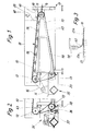
- Figur 1 eine Filtervorrichtung in stark vereinfachter Seitenansicht bzw. im Längsschnitt,
- Figur 2 eine Einzelheit der Vorrichtung gemäß Fig. 1 im Bereich der Reinigung eines Filter- Bandes,
- Figur 3 eine weitere Einzelheit der Vorrichtung gemäß Fig. 1 im Querschnitt, bei stark vergrößertem Maßstab,
- Figur4 eine Einzelheit über die Ausbildung des Filter-Bandes im Querschnitt, bei stark vergrößertem Maßstab,
- Figur 5 eine Einzelheit der Filtervorrichtung, nämlich die Randausbildung desselben, im Querschnitt bei gegenüber Fig. 1 vergrößertem Maßstab,
- Figur 6 einem Ausschnitt des Filter-Bandes im Grundriß,
- Figur 7 eine Einzelheit, nämlich einen Umlenkbereich für das Filter-Band im Querschnitt desselben,
- Figur 8 die Anordnung von Filteröffnungen im Filter-Band bei stark vergrößertem Maßstab,
- Figur 9 die Filteröffnungen gemäß Fig. bei geometrischer Verformung derselben,
Figur 10 einen Querschnitt durch die Filtervorrichtung gemäß Fig. 1,- Figur 11 eine Einzelheit in bezug auf die Führung des Filter-Bandes als Alternative zu Fig. 1.
- FIG. 1 shows a filter device in a greatly simplified side view or in longitudinal section,
- FIG. 2 shows a detail of the device according to FIG. 1 in the area of cleaning a filter belt,
- 3 shows a further detail of the device according to FIG. 1 in cross section, on a greatly enlarged scale,
- FIG. 4 shows a detail about the design of the filter band in cross section, on a greatly enlarged scale,
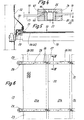
- FIG. 5 shows a detail of the filter device, namely the edge formation thereof, in cross section on a larger scale than in FIG. 1,
- FIG. 6 shows a section of the filter belt in plan view,
- FIG. 7 shows a detail, namely a deflection area for the filter band in cross section thereof,
- FIG. 8 shows the arrangement of filter openings in the filter band on a greatly enlarged scale,
- FIG. 9 shows the filter openings according to FIG. 1 when the same is geometrically deformed,
- FIG. 10 shows a cross section through the filter device according to FIG. 1,
- FIG. 11 shows a detail with regard to the guiding of the filter belt as an alternative to FIG. 1.
Die vorliegend als Ausführungsbeispiel dargestellte Filtervorrichtung ist primär für den Einsatz im Betrieb einer Rübenzuckerfabrik bestimmt, also zum Reinigen bzw. Filtern von Schwemmstrom-Wasser mit feinen Feststoffen, wie Sand und organischen Bestandteilen.The filter device shown here as an exemplary embodiment is primarily intended for use in the operation of a beet sugar factory, that is to say for cleaning or filtering flood water with fine solids, such as sand and organic constituents.
Eine Filterfläche der Vorrichtung wird dabei durch ein endloses Filter-Band 10 gebildet. Dieses wird gemäß Fig.1 über drei Umlenkwalzen 1.1, 12, 13 geführt, die in den Ecken eines Dreiecks angeordnet sind. Das Filter-Band 10 erhält dadurch in Seitenansicht eine annähernd dreieckförmige Gestalt. Die Umlenkwalze 11 ist zugleich als Spannwalze mit einer Spannvorrichtung 14 ausgebildet. Der Antrieb des ständig umlaufendes Filter-Bandes 10 wird durch die Umlenkwalze 12 bewirkt, die ihrerseits durch einen Motor 15 über einen Riementrieb 16 angetrieben ist. Die Umlenkwalzen 11, 12, 13 sind im übrigen in einem Traggestell 17 gelagert.A filter surface of the device is formed by an
Ein sich zwischen den Umlenkwalzen 11 und 12 erstreckender Obertrum 18 des Filter-Bandes 10 wirkt als Siebfläche. Um die dabei auftretenden Belastungen ohne nennenswerte Verformung aufnehmen zu können und ein Durchhängen des Obertrums 18 zu vermeiden, ist dieser durch eine Mehrzahl von unterseitig angeordneten Stützwalzen 19 geführt und unterstützt.An
Außerhalb des Bereichs der vorstehenden Siebfläche wird das Filter-Band 10 gereinigt. Bei dem vorliegenden Ausführungsbeispiel sind dem zwischen den Umlenkwalzen 12, 13 geführten Reinigungstrum 20 im einzelnen noch zu erläuternde Reinigungsaggregate zugeordnet. Der Reinigungstrum 20 ist durch die Anordnung der Umlenkwalzen 12, 13 so geführt, daß in diesem Bereich das Filter-Band 10 etwas aus der Vertikalen herausgeführt ist, so daß die beim Reinigungsprozeß anfallenden Feststoffe frei nach unten fallen können.The
Das Filter-Band 10 ist in besonderer Weise ausgebildet. Es besteht aus einem elastisch dehnbaren Werkstoff, insbesondere Kunststoff. Das Filter-Band 10 besteht aus mehreren, im Umlaufrichtung nebeneinanderliegenden Bahnen 21a, 21b, 21c. Diese sind so relativ zueinander angeordnet, daß sich zwischen benachbarten Bahnen 21a, 21 b.. eine Überlappung 22 ergibt.The
Jede Bahn 21a, 21 b.. wiederum besteht im vorliegenden Fall aus einzelnen rechteckigen Matten 23 von angemessener Größe. Die Matten 23 sind in Umlaufrichtung lösbar miteinander verbunden, so daß jede Matte 23 erforderlichenmalls individuell ausgewechselt werden kann. Beim vorliegenden Fall sind gemeinsame, quergerichtete Stoßstellen 27, 28 für die Matten 23 aller Bahnen 21 a, 21 b.. vorgesehen. Die Stoß- und Verbindungsstellen 27, 28 der Matten 23 werden hier durch Klemmleisten 24, 25 gebildet, die die einander zugekehrten Ränder aufeinanderfolgender Matten 23 erfassen und durch Formschluß sowie durch Klemmwirkung miteinander verbinden. Zu diesem Zweck ist jeweils zu beiden Seiten der Matten 23 eine Klemmleiste 24 bzw. 25 angeordnet. Beide Klemmleisten 24, 25 werden durch eine von oben bedienbare Verbindungsschraube 26 erfaßt und zusammengehalten.Each
Zur Bildung einer leicht herstellbaren, dauerhaften Verbindung zwischen den einzelnen Matten 23 sind diese an den einander zugekehrten Rändern im Bereich einer dort ebenfalls gebildeten Überdeckung mit Löchern 45 versehen. Diese werden unter Aufweiten über einen Haltezapfen 46 der Klemmleisten 24, 25 gedrückt und dadurch fixiert bzw. vorfixiert. Das obere, freie Ende dieser Haltezapfen 46 ist mit einer widerhakenähnlichen Verbreiterung 47 ausgebildet, über die die Matten 23 unter Aufweiten der Löcher45 gedrückt werden. Wie aus Fig.4 ersichtlich, kommen in diesem Bereich je zwei Matten 23 mit den Rändern übereinander zu lie- .gen. Der Haltezapfen 46 ist beispielsweise mit Gewinde in der unteren Klemmleiste 25 verankert. Eine mit Innengewinde versehene Bohrung in dem Haltezapfen 46 nimmt die Verbindungsschraube 26 auf, wodurch die Klemmleisten 24, 25 unter Ausübung eines erheblichen Klemmdruckes gegeneinander bzw. gegen die Matten 23 gedrückt werden.To form an easily produced, permanent connection between the
Die Klemmleisten 24, 25 bestehen aus einzelnen Abschnitten, jeweils mit einer Länge, die der Breite einer Bahn 21a, 21 b.. entspricht. Im vorliegenden Fall sind die Abschnitte der jeweils oben liegenden Klemmleisten 24 im Bereich der Überlappung 22 mit einer ebenfalls überlappend ausgebildeten Stoßstelle 27 versehen. Hierzu versetzt sind Stoßstellen 28 der unteren Klemmleisten 25 vorgesehen.The terminal strips 24, 25 consist of individual sections, each with a length that corresponds to the width of a
Die auf diese Weise über die gesamte Breite des Filter-Bandes 10 durchgehenden Klemmleisten 24, 25 bewirken eine Stabilisierung des Filter-Bandes 10 und zugleich eine Führung im seitlichen Bereich. Zu diesem Zweck sind an den freien, über das Filter-Band 10 hinwegstehenden Enden der Klemmleisten 24, 25 Stützrollen 29 angeordnet, die an einer aufrechten seitlichen Führungsschiene 30 der Vorrichtung im Bereich des Obertrums 18 Anlage erhalten. Wie aus Fig. 5 ersichtlich, sind diese Stützrollen 29 außerhalb des Filterbereichs angeordnet, der seitlich durch eine elastische Begrenzung in Gestalt eines auf dem Filter-Band 10 aufliegenden Dichtlappens 31 begrenzt ist. Dieser Dichtlappen 31 wiederum ist an einer hier nach innen vorspringenden Seitenwand 32 angeordnet, die ihrerseits den Raum bzw. Bereich für die Aufnahme der zu reinigenden Flüssigkeit begrenzt.The clamping strips 24, 25 which extend in this way over the entire width of the
Das Filter-Band 10 kann mit verhältnismäßig kleinen Filteröffnungen 33 ausgestattet sein. Diese sind im vorliegenden Fall (Fig. 8) rechteckig ausgebildet und erstrecken sich in Längsrichtung, also in Bewegungsrichtung des Filter- Bandes 10. Die in Reihen angeordneten Filteröffnungen 33 sind versetzt bzw. « auf Lücke zueinander angeordnet. Dadurch und durch die Materialeigenschaft des Filter-Bandes 10 ist eine Verformung der Filteröffnungen 33 im Sinne von Fig.9 möglich, nämlich durch Querdehnen des Filter-Bandes 10. Eventuell in den feinen Filteröffnungen 33 eingeklemmte Feststoffpartikel können dadurch entfernt werden, insbesondere in Verbindung mit einem Reinigungsaggregat 35.The
Die Querdehnung des Filter-Bandes 10 im vorstehenden Sinne erfolgt im Bereich der Umlenkwalze 13, die auf ihrem Mantel mit ringförmig angeordneten Rippen 34 versehen ist. Die Rippen 34 bestehen im vorliegenden Fall aus aufgeschweißten Ringen aus Rundmaterial. Alternativ können die Rippen 34 schraubenförmig angeordnet sein, wodurch bewirkt ist, daß das Filter-Band 10 während der sich wiederholenden Umläufe in verschiedenen Bereichen über die Breite gesehen gespannt bzw. gereckt wird.The transverse stretching of the
Infolge der Längsspannung des Filter- Bandes 10 ergibt sich die aus Fig. 7 ersichtliche Querschnittsform des Filter-Bandes 10 im Bereich der Umlenkwalze 13, mit der Folge, daß die Filteröffnungen 33 im Sinne von Fig. 9 aufgeweitet werden. Die Filteröffnungen 33 können dadurch kleinste Breitenabmessungen, beispielsweise herab bis zu 0,1 mm, aufweisen.As a result of the longitudinal tension of the
Ein dem Reinigungstrum 20 zugeordnetes Reinigungsaggregat 35 umfaßt im vorliegenden Fall eine dem Reinigungstrum 20 zustellbare Reinigungsleiste 36. Diese wird derart angetrieben, daß sie zu dem Filter-Band 10 eine Relativbewegung ausführt, derart, daß dieses Reinigungswerkzeug klopfend bzw. schlagend an das Filter- Band 10 heranbewegt wird. Zu diesem Zweck ist ein Kurbeltrieb 37 für die Bewegung der Reinigungsleiste36 vorgesehen.A
In Bewegungsrichtung nachgeordnet ist ein feststehender, elastischer Abstreifer 38, der sich ebenfalls über die gesamte Breite des Filter- Bandes 10 erstreckt. Dieser aus elastischem Material bestehende Abstreifer 38 liegt ständig an dem sich bewegenden Filter-Band 10 an. Durch einen gewissen Anpreßdruck werden im Bereich der aufgeweiteten Filteröffnungen 33 in diesen sitzende Feststoffpartikel herausgezogen, insbesondere Fäden etc.Downstream in the direction of movement is a fixed,
Zusätzlich kann in diesem Bereich eine im einzelnen nicht dargestellte chemische Reinigung, also eine Behandlung des Filter-Bandes 10 mit geeigneten Chemikalien, erfolgen.In addition, chemical cleaning, not shown in detail, that is to say treatment of the
Die Filterfläche des Filter-Bandes 10, nämlich der Obertrum 18, findet jeweils Aufnahme in einem nach oben offenen Behälter, der eintrittsseitig durch die geneigte Anordnung des Obertrums 18 eine größere Tiefe aufweist. Hier wird die Flüssigkeit über einen Überlauf 39 zugeführt. Dem Überlauf 39 wiederum ist eine sich quer erstreckende Auffangrinne 40 vorgeordnet, in der gegebenenfalls vorhandene Energie des zuströmenden Wassers vernichtet wird. Gleiche Aufgabe hat auch ein oberhalb der Auffangrinne 40 angeordnetes Prallblech 41. Durch den Überlauf 39 in Verbindung mit der Seitenwand 32 und dem Obertrum 18 wird so ein Behälter für die Aufnahme der zu reinigenden Flüssigkeit geschaffen, aus dem die Filterfläche durch fortlaufende Bewegung des Fllter-Bandes 10 ständig herausbewegt wird.The filter surface of the
Figur 3 zeigt ein Detail des Filter-Bandes 10 im Bereich der Überlappungen 22. Um den Eintritt von Feststoffpartikeln in den Bereich zwischen den einander überlappenden Bahnen 21a, 21b.. zu vermeiden, ist hier ein elastischer Niederhalter42 oberhalb des Filter-Bandes 10 jeweils im Bereich der Überlappungen 22 angeordnet. Der lappenartige bzw. streifenförmige Niederhalter 42 ist oberhalb des Filter-Bandes 10 in entsprechenden Halteschienen 48 verankert, derart, daß der bogenförmig um 90° umgelenkte Niederhalter42 mit einem entsprechenden Anpreßdruck im Bereich der Überlappung 22 auf dem Filter-Band 10 aufliegt. Relativanordnung und Abmessungen des Niederhalters 42 sind so gewählt, daß die im Bereich der Überlappung 22 gebildete freie Stufe überdeckt ist.FIG. 3 shows a detail of the
Dem gleichen Thema dient die Ausgestaltung gemäß Fig. 11, nämlich die Anordnung der Stützwalzen 19 längs eines Bogens. Dadurch wird das Filter-Band 10 im Bereich des Obertrums 18 polygonartig geführt. Die freiliegenden Abschnitte des Filter-Bandes 10 erhalten dadurch eine höhere Spannung, so daß die einander überlappenden Ränder der Bahnen 21a, 21b.. mit größerer Anpreßkraft aneinanderliegen und den Eintritt von Feststoffen verhindern.The configuration according to FIG. 11 serves the same subject, namely the arrangement of the
Unterhalb des nahezu gesamten Obertrums 18 wird ein großräumiger Behälter43 für die Aufnahme der gereinigten Flüssigkeit gebildet. Aus diesem kann das. Wasser über vorzugsweise beidseits angeordnete große Austrittsöffnungen 44 abgeführt werden.Below the almost entire
Unterhalb der Auffangrinne 40, nämlich im Bereich des Überlaufs 39, ist eine elastische, auf dem Filter-Band 10 aufliegende Schürze 49 gebildet, die im wesentlichen in gleicher bzw. ähnlicher Weise ausgebildet ist wie der Dichtlappen 31 im Bereich der Seitenwand 32. Aufgabe dieser Schürze 49 ist einmal die Abdichtung des hier gebildeten « Bahälters zur Aufnahme der zu reinigenden Flüssigkeit auf der « Talseite » des Filter-Bandes 10. Zum anderen hat die fest angeordnete, quer zum Filter-Band 10 gerichtete Schürze 49 die Funktion eines weiteren Reinigungselements. Eventuell auf bzw. an dem Filter- Band 10 in diesem Bereich noch haftende Feststoffe werden hier entfernt.Below the collecting
Die in fester Relativstellung angeordneten Reinigungselemente, insbesondere der Abstreifer 38 sowie die vorgenannte Schürze 49, werden ihrerseits permanent von den aufgefangenen Rückständen befreit, und zwar durch die als Erhöhung auf dem Filter-Band 10 angeordneten Klemmleisten 24. Diese werden entsprechend der Länge der Matten 23 aufeinanderfolgend an dem Abstreifer 38 sowie der Schürze 49 vorbeigeführt, mit der Folge, daß hier abgelagerte Feststoffteile durch die Klemmleisten 24 mitgenommen werden.The cleaning elements arranged in a fixed relative position, in particular the
Claims (12)
Priority Applications (1)
| Application Number | Priority Date | Filing Date | Title |
|---|---|---|---|
| AT79104163T ATE1565T1 (en) | 1978-11-02 | 1979-10-27 | DEVICE FOR FILTERING LIQUIDS CONTAINING SOLIDS. |
Applications Claiming Priority (2)
| Application Number | Priority Date | Filing Date | Title |
|---|---|---|---|
| DE2847503 | 1978-11-02 | ||
| DE19782847503 DE2847503A1 (en) | 1978-11-02 | 1978-11-02 | DEVICE FOR FILTERING SOLIDS CONTAINING SOLIDS |
Publications (2)
| Publication Number | Publication Date |
|---|---|
| EP0010747A1 EP0010747A1 (en) | 1980-05-14 |
| EP0010747B1 true EP0010747B1 (en) | 1982-09-22 |
Family
ID=6053666
Family Applications (1)
| Application Number | Title | Priority Date | Filing Date |
|---|---|---|---|
| EP79104163A Expired EP0010747B1 (en) | 1978-11-02 | 1979-10-27 | Apparatus for filtering solids-containing liquids |
Country Status (3)
| Country | Link |
|---|---|
| EP (1) | EP0010747B1 (en) |
| AT (1) | ATE1565T1 (en) |
| DE (2) | DE2847503A1 (en) |
Families Citing this family (2)
| Publication number | Priority date | Publication date | Assignee | Title |
|---|---|---|---|---|
| NL8300712A (en) * | 1983-02-25 | 1984-09-17 | Esmil Hubert Bv | BAND FILTER. |
| FR2596416A1 (en) * | 1986-03-27 | 1987-10-02 | Siderurgie Fse Inst Rech | METHOD AND DEVICE FOR CONTROLLING THE POSITIONING OF AN INJECTION LANCE IN A METALLURGICAL CONTAINER |
Family Cites Families (5)
| Publication number | Priority date | Publication date | Assignee | Title |
|---|---|---|---|---|
| US1663298A (en) * | 1925-06-17 | 1928-03-20 | Goodrich Co B F | Rubber filter sheet |
| US2173256A (en) * | 1938-10-01 | 1939-09-19 | Us Rubber Co | Method and apparatus for filtering |
| DE1285454B (en) * | 1966-07-30 | 1968-12-19 | Krauss Maffei Imp Gmbh | Cake removal device for drum filter with draining filter cloth |
| US3703963A (en) * | 1969-07-24 | 1972-11-28 | Ebara Infilco | Sludge hydroextractor |
| US3570674A (en) * | 1969-10-14 | 1971-03-16 | American Air Filter Co | Liquid filter apparatus |
-
1978
- 1978-11-02 DE DE19782847503 patent/DE2847503A1/en not_active Withdrawn
-
1979
- 1979-10-27 DE DE7979104163T patent/DE2963748D1/en not_active Expired
- 1979-10-27 AT AT79104163T patent/ATE1565T1/en not_active IP Right Cessation
- 1979-10-27 EP EP79104163A patent/EP0010747B1/en not_active Expired
Also Published As
| Publication number | Publication date |
|---|---|
| ATE1565T1 (en) | 1982-10-15 |
| EP0010747A1 (en) | 1980-05-14 |
| DE2847503A1 (en) | 1980-05-08 |
| DE2963748D1 (en) | 1982-11-04 |
Similar Documents
| Publication | Publication Date | Title |
|---|---|---|
| DE2330915A1 (en) | METHOD AND DEVICE FOR SEPARATING SOLIDS FROM LIQUIDS | |
| DE102007036553A1 (en) | Device for separating paint overspray | |
| EP0581770A1 (en) | Screening rake. | |
| DE3409826A1 (en) | FILTER DEVICE FOR SEPARATING SOLIDS FROM LIQUIDS | |
| EP2563973B1 (en) | Screening belt machine | |
| EP0010747B1 (en) | Apparatus for filtering solids-containing liquids | |
| DE3003827C2 (en) | Device for mechanical purification of water | |
| AT515829B1 (en) | computing device | |
| DE2745141A1 (en) | DUST FILTER | |
| EP2868822A1 (en) | Sieve device for separating and removing contaminants from waste water | |
| DE102007036551B4 (en) | Device for separating overspray | |
| EP0563081B1 (en) | Process for cleaning a drop separator and drop separator with cleaning device | |
| DE2318729A1 (en) | WASHING DEVICE FOR BEETS OD. DGL | |
| DE19727354A1 (en) | Waste water screening apparatus to remove coarse solid objects | |
| DE3725651C1 (en) | Band filter for cleansing liq. - includes upper chamber to hold dirty liq. filter band drive unit and cleansing chamber | |
| DE19746368A1 (en) | Sieve band machine for removal of solids from e.g. power station cooling water | |
| DE1407956A1 (en) | Dry filter cleaning system | |
| DE102011011759A1 (en) | Magnetic separator for separating ferromagnetic particles from liquid, has sheet made of stainless steel provided with stationary flat bottom, where liquid is applied directly on sheet by liquid application device | |
| DE2925974C2 (en) | Computing device for removing foreign bodies from a computing grate | |
| DE1700712U (en) | FILTER. | |
| DE19919690C2 (en) | Filter stage rake for collecting and dispensing solid components from flowing liquids | |
| DE3445123A1 (en) | Filter unit for air dedusting, particulary usable in mining | |
| DE20215591U1 (en) | Conveyor belt filtering device used for mechanically cleaning liquids contaminated with solids comprises endless filter belt having filtering elements connected to each other by hinge, drive for belt, and frame | |
| DE3433435A1 (en) | Sieve apparatus for purifying waters and waste waters | |
| DE1817484C (en) | Horizontally movable wall parts of a chamber for the production of glass fiber mats and strands |
Legal Events
| Date | Code | Title | Description |
|---|---|---|---|
| PUAI | Public reference made under article 153(3) epc to a published international application that has entered the european phase |
Free format text: ORIGINAL CODE: 0009012 |
|
| AK | Designated contracting states |
Designated state(s): AT BE DE FR GB IT NL SE |
|
| 17P | Request for examination filed | ||
| ITF | It: translation for a ep patent filed | ||
| GRAA | (expected) grant |
Free format text: ORIGINAL CODE: 0009210 |
|
| AK | Designated contracting states |
Designated state(s): AT BE DE FR GB IT NL SE |
|
| PG25 | Lapsed in a contracting state [announced via postgrant information from national office to epo] |
Ref country code: SE Free format text: THE PATENT HAS BEEN ANNULLED BY A DECISION OF A NATIONAL AUTHORITY Effective date: 19820922 |
|
| REF | Corresponds to: |
Ref document number: 1565 Country of ref document: AT Date of ref document: 19821015 Kind code of ref document: T |
|
| REF | Corresponds to: |
Ref document number: 2963748 Country of ref document: DE Date of ref document: 19821104 |
|
| PGFP | Annual fee paid to national office [announced via postgrant information from national office to epo] |
Ref country code: AT Payment date: 19901011 Year of fee payment: 12 |
|
| PGFP | Annual fee paid to national office [announced via postgrant information from national office to epo] |
Ref country code: FR Payment date: 19901012 Year of fee payment: 12 |
|
| PGFP | Annual fee paid to national office [announced via postgrant information from national office to epo] |
Ref country code: GB Payment date: 19901018 Year of fee payment: 12 |
|
| PGFP | Annual fee paid to national office [announced via postgrant information from national office to epo] |
Ref country code: DE Payment date: 19901026 Year of fee payment: 12 |
|
| ITTA | It: last paid annual fee | ||
| PGFP | Annual fee paid to national office [announced via postgrant information from national office to epo] |
Ref country code: NL Payment date: 19901031 Year of fee payment: 12 |
|
| PGFP | Annual fee paid to national office [announced via postgrant information from national office to epo] |
Ref country code: BE Payment date: 19901129 Year of fee payment: 12 |
|
| PG25 | Lapsed in a contracting state [announced via postgrant information from national office to epo] |
Ref country code: GB Effective date: 19911027 Ref country code: AT Effective date: 19911027 |
|
| PG25 | Lapsed in a contracting state [announced via postgrant information from national office to epo] |
Ref country code: BE Effective date: 19911031 |
|
| BERE | Be: lapsed |
Owner name: GERLACH GUNTER Effective date: 19911031 |
|
| PG25 | Lapsed in a contracting state [announced via postgrant information from national office to epo] |
Ref country code: NL Effective date: 19920501 |
|
| NLV4 | Nl: lapsed or anulled due to non-payment of the annual fee | ||
| GBPC | Gb: european patent ceased through non-payment of renewal fee | ||
| PG25 | Lapsed in a contracting state [announced via postgrant information from national office to epo] |
Ref country code: FR Effective date: 19920630 |
|
| PG25 | Lapsed in a contracting state [announced via postgrant information from national office to epo] |
Ref country code: DE Effective date: 19920701 |
|
| REG | Reference to a national code |
Ref country code: FR Ref legal event code: ST |
|
| PLBE | No opposition filed within time limit |
Free format text: ORIGINAL CODE: 0009261 |
|
| STAA | Information on the status of an ep patent application or granted ep patent |
Free format text: STATUS: NO OPPOSITION FILED WITHIN TIME LIMIT |