EP0010492A2 - Akusto-optische Flüssigkristallzelle und ein eine solche Zelle enthaltendes Sichtgerät - Google Patents
Akusto-optische Flüssigkristallzelle und ein eine solche Zelle enthaltendes Sichtgerät Download PDFInfo
- Publication number
- EP0010492A2 EP0010492A2 EP79400745A EP79400745A EP0010492A2 EP 0010492 A2 EP0010492 A2 EP 0010492A2 EP 79400745 A EP79400745 A EP 79400745A EP 79400745 A EP79400745 A EP 79400745A EP 0010492 A2 EP0010492 A2 EP 0010492A2
- Authority
- EP
- European Patent Office
- Prior art keywords
- cell
- liquid crystal
- acoustic
- walls
- layer
- Prior art date
- Legal status (The legal status is an assumption and is not a legal conclusion. Google has not performed a legal analysis and makes no representation as to the accuracy of the status listed.)
- Granted
Links
Images


Classifications
-
- G—PHYSICS
- G10—MUSICAL INSTRUMENTS; ACOUSTICS
- G10K—SOUND-PRODUCING DEVICES; METHODS OR DEVICES FOR PROTECTING AGAINST, OR FOR DAMPING, NOISE OR OTHER ACOUSTIC WAVES IN GENERAL; ACOUSTICS NOT OTHERWISE PROVIDED FOR
- G10K11/00—Methods or devices for transmitting, conducting or directing sound in general; Methods or devices for protecting against, or for damping, noise or other acoustic waves in general
- G10K11/02—Mechanical acoustic impedances; Impedance matching, e.g. by horns; Acoustic resonators
-
- G—PHYSICS
- G01—MEASURING; TESTING
- G01H—MEASUREMENT OF MECHANICAL VIBRATIONS OR ULTRASONIC, SONIC OR INFRASONIC WAVES
- G01H9/00—Measuring mechanical vibrations or ultrasonic, sonic or infrasonic waves by using radiation-sensitive means, e.g. optical means
- G01H9/002—Measuring mechanical vibrations or ultrasonic, sonic or infrasonic waves by using radiation-sensitive means, e.g. optical means for representing acoustic field distribution
-
- G—PHYSICS
- G01—MEASURING; TESTING
- G01N—INVESTIGATING OR ANALYSING MATERIALS BY DETERMINING THEIR CHEMICAL OR PHYSICAL PROPERTIES
- G01N29/00—Investigating or analysing materials by the use of ultrasonic, sonic or infrasonic waves; Visualisation of the interior of objects by transmitting ultrasonic or sonic waves through the object
- G01N29/04—Analysing solids
- G01N29/06—Visualisation of the interior, e.g. acoustic microscopy
-
- G—PHYSICS
- G01—MEASURING; TESTING
- G01N—INVESTIGATING OR ANALYSING MATERIALS BY DETERMINING THEIR CHEMICAL OR PHYSICAL PROPERTIES
- G01N29/00—Investigating or analysing materials by the use of ultrasonic, sonic or infrasonic waves; Visualisation of the interior of objects by transmitting ultrasonic or sonic waves through the object
- G01N29/22—Details, e.g. general constructional or apparatus details
- G01N29/24—Probes
- G01N29/2418—Probes using optoacoustic interaction with the material, e.g. laser radiation, photoacoustics
- G01N29/2425—Probes using optoacoustic interaction with the material, e.g. laser radiation, photoacoustics optoacoustic fluid cells therefor
-
- G—PHYSICS
- G02—OPTICS
- G02F—OPTICAL DEVICES OR ARRANGEMENTS FOR THE CONTROL OF LIGHT BY MODIFICATION OF THE OPTICAL PROPERTIES OF THE MEDIA OF THE ELEMENTS INVOLVED THEREIN; NON-LINEAR OPTICS; FREQUENCY-CHANGING OF LIGHT; OPTICAL LOGIC ELEMENTS; OPTICAL ANALOGUE/DIGITAL CONVERTERS
- G02F1/00—Devices or arrangements for the control of the intensity, colour, phase, polarisation or direction of light arriving from an independent light source, e.g. switching, gating or modulating; Non-linear optics
- G02F1/01—Devices or arrangements for the control of the intensity, colour, phase, polarisation or direction of light arriving from an independent light source, e.g. switching, gating or modulating; Non-linear optics for the control of the intensity, phase, polarisation or colour
- G02F1/13—Devices or arrangements for the control of the intensity, colour, phase, polarisation or direction of light arriving from an independent light source, e.g. switching, gating or modulating; Non-linear optics for the control of the intensity, phase, polarisation or colour based on liquid crystals, e.g. single liquid crystal display cells
-
- G—PHYSICS
- G01—MEASURING; TESTING
- G01N—INVESTIGATING OR ANALYSING MATERIALS BY DETERMINING THEIR CHEMICAL OR PHYSICAL PROPERTIES
- G01N2291/00—Indexing codes associated with group G01N29/00
- G01N2291/04—Wave modes and trajectories
- G01N2291/042—Wave modes
- G01N2291/0421—Longitudinal waves
Definitions
- the present invention relates to the field of acoustic imaging with liquid crystal detectors and relates more particularly to the production of nematic liquid crystal acousto-optical cells with laminated walls, making it possible to convert the acoustic hologram of an object directly and instantly. and its internal structures into a visible image. These cells make it possible to achieve, with the appropriate methods also described, a sensitivity to acoustic energy, a resolving power and a dynamic range considerably improved compared to the previous methods.
- acoustic imaging or holography we are primarily interested in the various means of obtaining a visual representation of objects or bodies and more particularly of their hidden structure by irradiating them with acoustic energy that they can transmit, reflect. or diffract in a general way, then by detecting the latter to draw an interpretable image.
- Acousto-optic cells make it possible to visualize the various parts of solid or liquid bodies transparent to ultrasound by converting the acoustic image or hologram of these bodies directly into a visible image, using a light source.
- ultrasound ultrasound is commonly used in medicine and non-destructive testing materials to obtain bi-dimensional images of the interior of the bodies.
- axial tomographies of an object or even views along a plane transverse to the ultrasound beam can be obtained by ultrasound.
- Some systems have a single mechanically displaced ultrasonic transducer and operate quite slowly.
- Others have a multiplicity of transducers fixed in a rectilinear or two-dimensional matrix, supplied in phase by very complex electronics.
- Liquid surface relief acoustic holography is also a technique used. Its principles and achievements are particularly described in US patents 3,879,989 and 3,765,403 to BB Brenden. The latter wrote an article on the question: "History and Present Status of Liquid Surface Acoustical Holography", J. Acoust. Soc. Am., Vol. 58, No. 5 (1975), p. 951-955.
- the image of the object is formed by an acoustic lens on a liquid surface which acts as a detector.
- a second beam of coherent acoustic energy is directed towards the surface where a network of wrinkles is formed constituting the acoustic hologram of the object.
- the acoustic imaging systems based on this method are of low sensitivity and the images produced contain significant defects due to the coherence of the ultrasound.
- the detector being a liquid surface, the geometry of use is necessarily limited and it is subject to parasitic vibrations.
- This quadratic detector is formed by a suspension of metallic micro-disks in a dense liquid, in a thin layer between walls transparent to ultrasound. An acoustic field is made visible by the reorientation and migration of the micro-discs it produces. However, the sensitivity of the device is low (1 mW / cm 2 ) and its high response time greater than 1 second.
- Another prior process is the liquid crystal cell described by Gréguss in the article mentioned above. This device is described more precisely in another article by the same author: "A New Liquid Crystal Acoustical-to-Optical Display", Acustica, vol. 29, No. 1 (1973).
- This prior device uses a layer of liquid crystal whose sensitivity is very low: the incident ultrasonic intensity must be several mW / cm 2 to produce a visible interaction. This prior device also has a very narrow acoustic field. Furthermore, the coupling of acoustic modes in the walls produces parasitic shear vibrations giving undesirable visible figures.
- the object of the present invention is a variety making it possible to circumvent the drawbacks mentioned above relating to known acousto-optical detectors and more particularly the production of acousto-optical cells operating according to a new mode of coupling of the acoustic wave vector with the direction of the molecules of a nematic liquid crystal, this mode of coupling producing a distortion of the structure of the liquid crystal and a visible change in the optical properties of the latter for acoustic intensities much lower than those required in the anterior cells.
- the present invention relates to an acousto-optical cell, comprising an oriented liquid crystal layer, comprised between laminated walls having an acoustic impedance adapted to that of the propagation media adjacent to said walls, for extended values of the angles. incidence, the molecules forming said liquid crystal being reorientable in a plane substantially perpendicular to the direction of propagation of the incident ultrasonic energy, each wall including at least two layers transparent to said ultrasonic wave, and at least one of the walls being optically transparent.
- the invention also relates to various methods of using the present acousto-optical liquid crystal cells for acoustic visualization and holography.
- each cell wall used was made up of a single glass slide. This has the effect of considerably limiting the opening of the acoustic field of these cells: for angles of incidence different from 0 °, there is multiple reflection of the ultrasonic waves on the walls, which induces flows or turbulences in the liquid crystal producing disordered reorientations of the molecules and undesirable visible effects.
- the present cell is however based on the discovery of an effect very different from the previous ones, by which the acoustic vibrations produce an ordered molecular reorientation, without appreciable flow of the liquid crystal.
- the effect is manifested for ultrasonic intensities much lower than those used previously.
- This effect is also manifested in other types of liquid crystals, such as cholesterics and smectics.
- the present acousto-optical cell is not limited to any ultrasonic frequency in particular, but nevertheless gives remarkable results in a range of 0.5 to 15 MHz.
- FIG. 1 shows a layer of nematic liquid crystal 73, initially of homotropic structure 98, that is to say of which the molecules are oriented perpendicular to the walls 92 and 93.
- Acoustic radiation 94 is incident at an angle 9, 'and an intensity I which increases in the direction "Y".
- the long organic molecules of the liquid crystal (cl) tend to orient themselves perpendicular to the acoustic displacement so as to minimize the acoustic losses.
- the relative absence of multiple reflections of the acoustic waves between the walls is an essential condition for producing a usable visible effect. These walls must therefore be very transparent to acoustic waves 94.
- a characteristic of the present acousto-optical cells is to fulfill this latter condition almost perfectly at a given frequency, for extended values of the angle of incidence 8.
- the propagation media 96 and 97 can be identical or different liquids, and even one or both of the media can be solid, as long as the previous condition is satisfied.
- light transmission T by a homotropic nematic liquid crystal cell placed between crossed polarizers whose axes are inclined by 45 ° on the plane of incidence of the acoustic energy of the ultrasonic wave varies as illustrated in FIG.
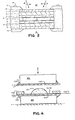
- FIG. 3 shows an embodiment of the present invention where the layer of cl 73 is included between rigid laminated walls 1, 2, 3 and 7, 8, 9.
- the layers 4 and 6 are very thin layers, mono- molecular, of a surfactant used to give the orient This is a well-known technique in the field and is particularly discussed in an article by FJ Kahn et al. : "Surfaceproduced aligment of liquid crystals", Proc. IEEE, vol. 61, No. 7 (1973), p. 823.
- a suitable surfactant for obtaining perpendicular (homotropic) alignment is lecithin, another is ammonium hexadecyl-trimethyl bromide, but they are by no means the only ones.
- the propagation media 90, 91 are the same acoustic impedance liquid: where p is the density of the liquid and c, the speed of sound in this liquid.
- Water is a suitable, but not exclusive, propagation medium.
- Most nematic compounds which have their mesophase or liquid crystal phase centered on a temperature of about 20 ° C can be used suitably.
- One such compound is a eutectic mixture (50% -50%) of MBBA (p-methoxy-benzylidene-pn-butylaniline) and EBBA (p-ethoxy-benzylidene-pn-butylaniline) which has negative dielectric anisotropy.
- a preferred structure is composed of a clear solid material 2 (or 8), of low acoustic impedance: between identical layers 1, 3 (or 7, 9) of a clear solid material of impedance: The value of Z 2 ( OR Z 8 ) is intermediate between Z o and Z 1 (or Z 3 , or Z 7 or Zg). The thickness of the various layers is determined by their acoustic impedance and the frequency of the ultrasound, as discussed below.
- Suitable materials for layers 1, 3, 7, 9 are, for example, glass, molten quartz, or other materials of high acoustic impedance. In one of the walls, one or both of these two layers may be of an opaque and reflective material. For example, in an embodiment where the materials are optically transparent, a reflective metallic film 16 of aluminum or silver can be deposited on the layer 7 or 8, so that the light 96 goes back and forth in cl 73.
- a suitable material for intermediate layers 2 and 3 is a polymer film, bonded to the other layers with clear cement. This material can also be a clear polyester resin injected between the adjacent lamellae 1, 3 (or 7, 9), which polymerizes and hardens over time.
- Figure 4 shows a technique for assembling this structure.
- the layers or lamellae 1, 7 and 3, 9 are applied to flat glass plates 100 and 101 by means of a liquid film 102, 103 which ensures firm adhesion.
- the contour is then sealed with a varnish 104, 105.
- a wedge in the form of a frame 106 determines the thickness of the resin.
- a sufficient quantity of this resin 107 (layer 2 or 8, fig. 3) is then deposited on the lower strip 3, then the upper assembly is applied to the wedge 106.
- the film conductor 15, 16 is placed between the. resin and the layer 3, 9.
- the electrical connection with the outside is provided by a metal tab 108 in contact with the conductive layer 15, 16. This gives a flat laminated wall whose dimensions can exceed 15 x 15 cm 2 and which is not bi-refractive.
- This intermediate medium 2 or 8 can also be a liquid, but at the expense of rigidity and uniformity of thickness.
- the material of high acoustic impedance can, conversely, be placed between layers of intermediate acoustic impedance.
- one or two of the optically transparent layers in the opposite sides of the cell can be made of a polarizing material.
- the cl is a homotropic nematic
- the two polarizers are crossed. But their mutual orientation is in no way restricted to this, particularly if the structure of the cl is homogeneous (molecules parallel to the walls) or twisted, or even if a cholesteric or smectic liquid crystal is used.
- One of the transparent layers can also be bi-refractive and constitute a phase, half-wave or quarter-wave plate.
- a wedge 10 in the form of a frame determines the thickness of the liquid crystal 73 (FIG. 3).
- the structure is held by frames 5 and 12, which are fixed together by bolts 14, and sealed with a putty or epoxy 13.
- These frames can, for example, be made of metal, ceramic or plastic.
- FIG. 5 represents a triple wall of materials with acoustic impedances Z I , Z 2 , Z 3 , of thicknesses d ⁇ , d 2 , d. 3 , between midpoints of propagation 90, 73, of impedances Z o , Z c
- the input impedance Z i presented by the structure to an acoustic wave 94 is a complex function: where f is the frequency of the wave.
- the reflection coefficient is given by formula 2 and the modulus of the transmission coefficient T is therefore:
- the transmission reaches almost 100% for a range of high angles of incidence.
- a characteristic of the embodiments of the present invention is an acoustic transmission close to 100% for incidences ⁇ of approximately -12 ° to + 12 ° and around + 45 °, as illustrated in FIG. 6.
- the ultrasound effect described above occurs visibly for ultrasonic intensities I less than 100 ⁇ W / cm 2 , without parasites.
- An important advantage of these multiple layers is their solidity: at equal thickness, they withstand stresses and shocks much better than simple glass walls, for example.
- the thicknesses d l , d 2 , d 3 of the different layers are of the same order of magnitude and between 100 and 200 ⁇ m for d 1 and d 3 , and between 15 and 125 ⁇ m for d 2 .
- a remarkable feature of the various embodiments is the maximum acousto-optical interaction in the liquid crystal made possible by the high acoustic transparency of the layers. If we refer to FIGS. 1 and 3, an acoustic wave 94, incident with an angle 8 on the laminated layers of the cell to cl will produce a distortion or rotation ⁇ (z) of the molecules, as a result of the torque given by the equation 1. The effective optical bi-refringence of the medium is consequently modified, which produces a phase shift ⁇ between the ordinary and extraordinary light waves coming from the incident wave 96.
- ⁇ can be calculated and deduce the light transmission T through the key by the known formula: where y is the angle between the plane of polarization of the incident light and the plane determined by the axis of the molecules and the normal to the layer.
- This equation shows that a variation in light transmission through the cl layer is consecutive to the incidence of acoustic energy which causes a distortion ⁇ (z) of the molecular structure and a phase shift ⁇ of the components of light.
- This light is monochromatic or quasi-chromatic, but in several cases, white light is sufficient.
- the key cell of FIG. 3 may include a reflective layer 16. In this case, the light 96 coming from the medium 90 goes back and forth in the key, which doubles the phase shift ⁇ .
- Equation (11) shows that for low values of ⁇ , the transmission T will then be four times higher than for a transparent cell seen that T is then proportional to the square of ⁇ . Consequently, to have a higher acousto-optical sensitivity, a reflective layer 16 will be used.
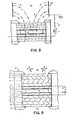
- FIG. 7 represents another embodiment of the acousto-optical cell where an electric field is produced within the cl 73 in order to quickly restore the initial orientation of the molecules which generally have a positive dielectric anisotropy.
- This field is created by electrically conductive layers 15, 16 of which at least one (15) is optically semi-transparent. They are connected to an alternating voltage source 17 with switch 27.
- the frequency used is generally between 50Hz and 25 kHz, with voltages between 2 and 200 volts.
- this embodiment is entirely identical to that of FIG. 3.
- the semi-transparent electrode of FIG. 7 is eliminated and replaced by an external electrode 176 immersed in the liquid medium 90.
- This medium preferably being a moderately ionized liquid, a fairly high fraction of the drop in alternating voltage occurs through the layer of liquid crystal 73, thus creating an alternating electric field E of reorientation of the molecules of the liquid crystal 73 when the source 17 is connected by closing the switch 27.
- FIG. 9 shows an embodiment of an acousto-optical liquid crystal cell, the principles and advantages of which are identical to those of FIGS. 3 and 7, except that the walls have more layers and are therefore stronger.
- the wall composed of the main layers 20, 19, 18, 2, 3 (or the other: 7, 8, 21, 32, 33), without counting the electrodes 15, 16 and the surfactant layers 4, 6, is equivalent to the superposition of two walls such as 1, 2, 3 in FIG. 3.
- the thickness of 18 (or 21) will be double that of 20 and 3 (or 7 and 33).
- the acoustic transmission T of such a structure is substantially the same as in FIG. 6, depending on the incidence ⁇ .
- the electrodes 15, 16 have the same function as in FIG.
- FIG. 7 restore the initial orientation of the molecules of l.s. by an electric field. It is also possible to omit at least one of the electrodes 15, 16 in certain embodiments as was said above with reference to FIG. 8. Other embodiments according to FIG. 9 may also include polarizing layers in the opposite walls. One of the layers can therefore constitute an optical phase plate as before.
- FIG. 10 represents an acoustic-optical liquid crystal cell which incorporates a matrix or network of integrated semiconductor photo-detectors, which directly gives electrical signals corresponding to the acoustic intensity in the liquid crystal 73.
- the input acoustic impedance Z i of the cell is adapted to those of the propagation media 90, 73, 91 by means of laminated walls, so that the acoustic energy 94 freely crosses the entire structure and exerts a maximum distortion action on the liquid crystal molecules 73.
- One of the layers 1, 2, 3 of the entry wall may have a polarizing material such as a dichroic suspension.
- One of the layers 7, 8 of the other wall is polarizing, so that in the rest state of 73 the light 96 does not reach the photodetectors 22.
- One of the layers between the polarizers can also be bi-refringent and act as a half-wave or quarter-wave plate.
- the acoustic energy 94 which passes through 73 produces a distortion of the structure which modifies the polarization state of the light 96 also passing through the liquid crystal 73. This modification is translated into a change in intensity of the light 96 which reaches a network of detectors 22 when the relative orientation of the polarizers is appropriate.
- the polarizers will be crossed.
- the detectors 22 can be an array of photodiodes, phototransistors, photoresistors or any other suitable detector known in the field of integrated circuits, including charge transfer devices.
- This matrix or network 22 is generally composed of mxn elements connected to multiple conductors 24, 25 relaying the signals produced by each element, in the two dimensions X and Y.
- FIG. 11 illustrates a different way of producing a maximum interaction between the incident acoustic energy 94 and the liquid crystal layer 73.
- the walls of the acousto-optical cell are made of polymer membranes 70, 76, stretched and glued to frames 78, 79. These can be joined by bolts 81 and sealed with cement 80.
- a shim 77 determines the thickness of the layer of liquid crystal 73.
- the membranes 70, 76 can also be composed of a polarizing material, the axes of which are crossed if the cl 73 is a nematic compound of homotropic structure. If the thickness of the layers 70, 71, 72 (or 74, 75, 76) is substantially less than a quarter of the wavelength of the incident acoustic energy 94, a high fraction of this will be transmitted through the wall.
- the layer 75 can be metallic, an aluminum deposit for example, and act as a mirror. In this case, the light 96 goes back and forth in the liquid crystal 73, and the cell is four times more sensitive than that which is transparent, as explained above.
- the layers 71, 75 of FIG. 11 are replaced by the electrodes 82, 83 of which at least one (82) is semi-transparent. Their function is to create in the liquid crystal 73, an electric field when they are connected to the voltage source 17. This field quickly restores the resting orientation of the molecules as explained above. Otherwise, the cell is identical in all respects to that of FIG. 11.
- FIG. 13 The arrangement of FIG. 13 is similar to that of FIGS. 11 and 12, except that the membranes 70, 76 are replaced respectively by the membranes 84, 85 and 86, 87.
- One of the joined membranes acts as a polarizer, the other can act either as a phase plate or as a quarter wave plate, or can be simply isotropic, as required. Otherwise, this cell or acousto-optical liquid crystal converter is identical in all respects to those of FIGS. 11 and 12.
- Figure 14 shows the action of two coherent longitudinal ultrasonic waves 200, 201 on the orient tation of a liquid crystal 202, when the initial orientation of its molecules is perpendicular to the walls (homotropic structure).
- the movement of the molecules of cl is elliptical (203) due to the phase shift of the vibrations produced by 200 and 201.
- the molecules then tend to orient themselves along their major axis or director axis, substantially in the direction of the minor axis 204 of the movement. Even more generally, the molecules tend to reorient locally in a direction such that the losses of acoustic energy are minimal. Such a direction exists as a result of the anisotropy of the viscosity of a liquid crystal.
- the vibrations 205A, 206A corresponding respectively to the waves 200, 201 are in phase and the movement 207A of the molecules is rectilinear. It follows that the molecules tend to reorient in the direction 208A perpendicular to 207A.
- the vibration 205B is 180 ° out of phase with respect to 205A, while 206A and 206B are in phase, so that the resulting vibration 207B occurs in a different direction of 207A.
- the molecules then tend towards orientation 208B, different from 208A.
- FIG. 15 represents the effect of these reorientations on the polarized light transmitted by the cl.
- the reorientation 204 of the molecules of cl 202 occurring in the plane of the figure, the cell is placed between crossed polarizers 210, 211, whose axes are inclined by 45 ° in the plane of the figure.
- the incident plane light waves 212 emerge from the liquid crystal 202 with a generally elliptical polarization 213.
- the intensity I of the light 214 transmitted by the analyzer 211 therefore varies periodically as indicated on the graph of I (x) in function of x.
- the spatial variations or modulations of the orientation of the cl molecules are thus translated into spatial variations of light intensity.
- Acoustic interference fringes are therefore directly visible as optical interference fringes. If an acoustic hologram is formed in the key layer in a cell according to the present invention, this hologram is directly and instantly transformed into an optical hologram.
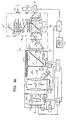
- FIG. 16 illustrates a device using the nematic liquid crystal acousto-optical cells operating by reflection, of one of the types described above.
- the assembly constitutes a holographic ultrasonic camera making it possible to examine objects and their interior by transmission or diffusion of ultrasonic waves.
- the device makes it possible to convert the acoustic hologram of an object and its internal structures, directly and instantly into an optical hologram.
- Another feature of the device is that it can translate the latter hologram instantly into an image of the object by an electronic method.
- an image of acoustic intensity or an image of acoustic phase can be obtained at will.
- the main enclosure 117 is filled with a liquid 125 which may be water or any other liquid which easily transmits ultrasonic energy.
- the acousto-optic cell at cl 120 is substantially perpendicular to axis 116 of the system.
- the object 124 can be placed in a different liquid medium 126, separated from the medium 125 by an acoustically transparent membrane 150.
- a large area ultrasonic transducer 127 produces substantially planar waves for examining the object 124 by transmission.
- This transducer can be in contact with the object if necessary.
- Another transducer 149 can be used independently for the lateral irradiation of 124. In this case, the acoustic energy scattered by the various parts of the object serves to form an acoustic image on the cell 120.
- the same transducer can also occupy alternately positions 127 or 149.
- the transducer 127, for examination by transmission can pivot, with two degrees of freedom, substantially around the center 0 of the acoustic objective 121.
- the transducer 149 for examination by diffusion can likewise pivot around a point located near the object.
- Another transducer 128 produces a plane acoustic wave 116 ′ of substantially uniform intensity which crosses the cell 120 and causes a general reorientation or pre-orientation of the molecules of the cl
- These transducers are excited by the same generator at high frequency 129 which can power amplifiers different for each transducer and giving coherent waves which interfere on 120.
- the image hologram of a transverse plane of the object 124 is thus formed on cell 120, as a result of the spatial modulation described. upper.
- acoustic energy coming from the lenses 121 passes through the cell 120 and is reflected on a plate of glass or any other isotropic transparent material 130 disposed at approximately 45 ° relative to the cell 120. This reflected energy is directed to an absorber 131.
- the latter can be formed of an assembly of prisms of an absorbent material for acoustic energy, such as rubber.
- most of the acoustic energy coming from the pre-orientation transducer 128 passes through the cell 120 and is absorbed by 131.
- the fraction of the energy reflected by the front face of 120 is also absorbed by the part before the absorber 131; in both cases, the point of the prisms is substantially oriented towards the incident energy.
- the plane light waves 160 used to obtain the optical hologram corresponding to the acoustic hologram propagate on the side of the cell 120 opposite to the acoustic lenses 121. They pass through the liquid crystal layer of the reflection cell 120 substantially according to normal and are reflected roughly in the same direction towards the external optical system 161 from which they originate. However, this configuration is in no way limiting.
- the light waves can propagate on the side of the acoustic lenses 121, which involves an optical mirror transparent to ultrasound or acoustic mirrors transparent to light.
- the cell 120 may be transparent to light, which involves either optically transparent acoustic mirrors, or acoustically transparent optical mirrors.
- Light energy can come from an inconsistent or coherent quasi-point source 132 associated with the condenser 133.
- This condenser can particularly include an infrared filter 134 and. a color filter or an interference filter 162, or any other type of optical filter.
- the conical beam 163 passing through the orifice 164 is refracted by the lens 135 which gives a substantially cylindrical beam 165, polarized by the filter 136.
- the axis of polarization of the latter must be parallel or perpendicular to the plane determined by the axes X ' X "and Y" Y “'of the optical system.
- the axis Y"Y''' must be inclined by an angle y on the plane of the figure which is the one, containing the axes XX 'and YY'.
- the angle there is found in formula 11 and preferably has a value of 45 ° or 135 °.
- Fig. 17 specifies this geometry.
- the beam 165 is divided into two parts of substantially equal intensities by the blade 137.
- One part is lost in a light trap or black body 144.
- the other part is refracted into a conical beam 166 by the lens 138.
- the focal points lenses 138 and 139 coinciding at F.
- the conical beam 166 which crosses the cylindrical diaphragm 167 160 after refraction by the collimating lens 139.
- a collimating lens 172 can also be embedded in the enclosure 117 and play both the role of a refracting element like the lens 139 of FIG. 16 and that of the sealed wall.
- the axis X'X "of the optical system can coincide with the axis XX 'of the acoustic part.
- the cylindrical beam 160 passes through the liquid crystal layer of the cell 120, is reflected on the opposite wall which carries a reflective layer and returns substantially in the same direction. Its polarization is then generally elliptical. It passes the lens 139 in the opposite direction, then converges towards the diaphragm 167 and the lens 138. The light beam becomes substantially cylindrical after refraction by the lens 138 and partly crosses the plate 137.
- a polarizer or analyzer 141 is placed on the path of light with its polarization axis substantially at right 'angles to that of 136, so that the light is normally blocked when the key 120 is at rest, without ultrasonic irradiation, since the polarization state of light passing through it is not modified.
- the light emerging from 141 then converges, by means of the lens 142 to an appropriate detector such as the eye of the observer 169, a camera 170, a video camera 143 or any other suitable detector.
- an appropriate detector such as the eye of the observer 169, a camera 170, a video camera 143 or any other suitable detector.
- the opening of the entrance detector or pupil approximately coincides with the focal point of the exit lens 142.
- the adjustment of the detector 169, 170, 143 or the like is done on the image of the cell 120 given by the diopter 140 and the lenses 139, 138 and 142.
- the optical axis X'X "of the optical system 161 makes an angle E by a few degrees with the axis XX ', in the plane of the figure or a neighboring plane, so that the fraction of the light energy which is reflected on the input face 140 of the enclosure 117 is blocked at its return through the diaphragm 167.
- Block 148 designates a central control system for the various functions associated with the liquid crystal cell ultrasonic camera.
- Figure 19 illustrates the stages of acquisition of the acoustic hologram of an object and restitution of a visible image.
- 19-a we see the intensity distribution of an acoustic image formed by the lenses 121 (fig. 16) in the plane of the cell at cl 120: in the MNPQ region, the intensity is uniform and greater than that of the surrounding area; AB is an observation line.
- the hologram-image seen on 120, through the optical system 161 by a detector 143, 169, 170 or other (fig. 16), is represented in 19-b.
- the MNPQ region corresponds to higher contrast interference fringes than those of the surrounding area.
- this hologram as a spatial carrier of period b whose amplitude is modulated by the acoustic intensity and whose phase or position is modulated ( ⁇ x) by the phase of the acoustic wave coming from the object.
- Fig. 19-c shows a period of the video signal corresponding to the line AB, as given by a camera 143 (fig. 16).
- the spatial carrier of period b along AB corresponds the temporal carrier of period T o or frequency f o whose amplitude A (t) is modulated by the contrast of the fringes of the hologram and whose phase ⁇ (t) is modulated by the position ⁇ x of the fringes of the hologram.
- the video signal is substantially of the form: where C (t) is a mean value varying little in the interval.
- the composite video signal synchronization pulses are designated by S.
- This signal is received by the processing system 145 (fig. 16) which can provide a clear, frosted visible image as in fig. 19-f.
- Figure 20 shows the main components of this system which we consider exclusive to the present process.
- the video signal (fig. 19-c) is amplified by 181: its appearance is then as in fig. 19-d.
- the amplitude is detected by a rectifier 182.
- the low-pass filter 183 having a cut-off frequency substantially equal to the fundamental frequency of the rectified signal gives the signal of FIG. 19-e.
- the summator 184 superimposes on the signal 19-e the synchronization pulses lost during the filtering and which are regenerated by the circuit 185.
- the signal is then amplified by 186 and directed towards a selector 190.
- the switches 187, 188 allow the signal to the camera 143 to bypass the demodulation system by the channel 189 and to display the hologram-image directly on the monitor 146.
- a central control device 148 (fig. 16 and 20) allows in particular to interqrconnect via 190 various elements such as the video monitor 146, pn video recorder 191, a video memory 192, a computer image and hologram processing system 193 or any other useful element.
- the signal (fig. 19-e) leaving the demodulation chain 180 to 186 gives on the monitor 146 an image as illustrated in fig. 19-f where the zone of higher luminance M'N'P'Q 'corresponds to the zone of greater ultrasonic intensity of the zone MNPQ of fig. 19-a.
- 19-a shows the hologram-image obtained when there is no object in front of the transducer 127 of FIG. 16: this is the background hologram.
- the expression of the video signal of this last hologram is substantially:
- This background hologram or reference hologram is used in particular to obtain a phase image of the acoustic object by means of the present method. If, in a first time, one takes a hologram of the bottom and one stores it in a video memory 192 or other 193 and which one superimposes in a second time the hologram-image of an acoustic object (fig. 19-b), one obtains the interference image hologram of this object.
- the interference hologram can be directly interpreted on the monitor 146 (fig. 16), or one can obtain the defrocked phase image by routing the video signal (eq. 14) to the input of the demodulation chain 180-186 ( Fig. 20) via link 194 and switch 195.
- This last interferential holography process makes it possible in particular to highlight in a unique and remarkable way minimal modifications s having occurred in a given object, relatively transparent to ultrasound, between two successive instants, or still to make visible very slight differences in structure and shape between two apparently identical objects according to current examination techniques.
- the acoustic hologram of an object and that we save it in a video memory.
- a line in this hologram can be represented by: Suppose now that we take a second hologram of the same object placed in exactly the same place, but which has undergone some deformation in the meantime, or the hologram of a second object, apparently identical, placed in the same place as the first.
- This second acoustic hologram is such that a period or line of the video signal can be represented by: If we subtract this second hologram from the first, the corresponding line becomes, with some algebraic manipulations, We can ask: We assumed that C 1 ⁇ Cz. ⁇ (t) measures the offset of a fringe of the second hologram relative to the fringe corresponding of the first: it is a function of the difference in phase shift of the acoustic waves coming from the same pbint of an object at two successive instants or of corresponding points of two different objects placed successively in the same place.
- this equation shows that the amplitude of the resulting signal is given by:
- This equation shows that the amplitude b (t) of the signal corresponding to the resulting interference hologram is a function of the disturbances ⁇ (t), caused by differences which can be very small between the two holograms and therefore by differences also very small. between two successive states of the same object in the same place or between two slightly different objects placed successively in the same place.
- this interference hologram or difference hologram can be directly interpretable on a video monitor 146 (fig. 16), or one can obtain the cleared difference image by routing the video signal v 3 (t) to the chain. demodulation 180-186 (fig. 20) by the link 194 and the switch 195.
- phase y (t) is given by:
- This difference image made by interference holography can also be obtained by the following methods or processes. Note also that by these same methods and processes, we can subtract the effect of a disturbing medium (or artefacts) intermediate from the object of interest and the camera, by first taking a hologram acoustics of the disturbing medium alone, then a second hologram with the object which is subtracted from the first as described. We thus obtain an image of the object which is much sharper and distinct than by current methods. It should also be mentioned that the disturbances ⁇ (t) can electronically modulate a color video signal so as to obtain a so-called "pseudo-color" image giving additional very interesting information on the object examined by ultrasound.
- Another way of obtaining the intensity image or the phase image of an acoustic object using the present method consists in routing the signal from the video camera 143 via the link 189 to an image processing system. by computer 193 using an appropriate algorithm with Fourier transformations.
- Another practical way of obtaining the phase image of an acoustic object is to record the background hologram on film using a camera 170 (fig. 16) and superimpose it optically on the image hologram of the object as seen on cell 120.
- This can be achieved in particular by means of the device of FIG. 21 which is added to the optical system of FIG. 16.
- the hologram of the background 220 previously photographed by 170 is placed in the vicinity of the focal plane object of a lens 221 which gives a virtual image of it on the uniform luminous background of a screen 222 lit by the blade 223.
- a semi-transparent plate 224 this image of the background hologram is superimposed on the image hologram seen through the output lens 142 of the optical system.
- the exact superimposition can be done by achieving the coincidence of the images of landmarks RSTU (fig. 19-g) recorded on the liquid crystal cell 120.
- An appropriate detector such as 143, 169, 170, or the like can then record the interference hologram image of an acoustic object.
- a phase image of this object can be obtained by demodulating, as explained above, the signal from a video camera 143 by means of the demodulation system 145 (FIGS. 16 and 20).
- a remarkable advantage of this latter method is that it is enough to light the lamp 223 (fig. 21) to instantly replace an intensity image by a phase image from the point of view of a detector 143, 169, 170 or other, with or without demodulation by the chain 180-186.
- a transverse movement 225 of the hologram 220 produced by a micrometric screw makes it possible to modify at will, by inversion of the contrasts, the appearance of the phase images obtained.
- the hologram written in the liquid crystal of cell 120 can be erased quickly by reorienting the molecules in an alternating electric field as it is said in the text relating to FIG. 7.
- the alternating voltage source 177 (fig. 16), actuated by the control system 148 can be connected to conductive layers of which at least one is semi-transparent, like the cell illustrated in fig. 7. Or, it can be connected to the reflective conductive layer 16 of FIG. 7 and to an electrode 176 (fig. 16) immersed in the external liquid 125 which is moderately conductive. In this case, the problem of the reflection of light is eliminated by a semi-transparent electrode such as 15 of FIG. 7.
- the present invention makes it possible to substantially correct the image defects caused by the coherence of the acoustic waves irradiating an object. It is a well known fact that this coherence leads to undesirable diffraction effects by structures of the object outside the plan of interest.
- One way to remedy this in other systems is the use of an acoustic source with a frequency varying between certain limits. In the present system, this defect is corrected by superimposing a series of images obtained by gradually varying the phase relationship between the different points of the object irradiated by an acoustic wave at fixed frequency. This phase variation is obtained essentially by modifying in stages the orientation of the transducers irradiating the object, as indicated in FIG. 16.
- the transducer 127 for transmission imaging can pivot around the point O substantially located at the center of the acoustic lens system 121, several image holograms are successively taken, then demodulated by means of the device 145 (FIGS. 16 and 20).
- the resulting images can be superimposed in a video memory 192 or in any image processing system 193. They can also be photographed successively and superimposed on the film by means of a camera placed in front of the video monitor 146.
- the transducer 127 driven by a mechanical, hydraulic, electric or other motor 175, can pivot independently in the plane of the figure and in a perpendicular plane passing through O.
- FIG. 16 shows three possible positions of the transducer 127 having pivoted in the plane of the figure .
- the rotation is typically less than 10 ° in the two planes.
- the transducer 149 for imaging by diffusion can pivot in a similar way around a point generally located on the other side of the object 124. The taking of the successive images and their superposition is then done in the same way than before,
- a visible image from the acoustic hologram of an object converted into a hologram visible by the cell 120 is illustrated in the fig. 22. It is a purely optical technique where the previous incoherent light source is replaced by a laser 23Q, associated with a lens 231 and a spatial filter 232 to give a beam of coherent light incident on an optical system substantially the same as before. .
- the converging beam 234 which emerges therefrom is refracted into a cylindrical beam 235 by the lens 139. This beam is diffracted by the hologram which forms in the liquid crystal of the cell 120 (fig. 16).
- the light is diffracted mainly in the spectra of order -1 (237), 0 (238) and +1 (239).
- the spatial filter 236 By means of the spatial filter 236, the first two are blocked by letting the light energy of the last pass.
- This energy emerges from the optical system in the form of a beam 240 converging on an appropriate detector, such as a video camera 143, a photographic camera 170, the eye of an observer 169 or any other detector.
- an appropriate detector such as a video camera 143, a photographic camera 170, the eye of an observer 169 or any other detector.
- FIG. 23 shows another method of using a reflecting crystal cell in the case where it is not required to use hydro-acoustic lenses to form the acoustic image of an object.
- This method can be used in particular when one wishes to have a visual representation of the intensity distribution in front of a transducer or even, to visualize the acoustic shadow cast by an object (ombroscopy).
- the device is simpler than that of FIG. 16, but the two have certain elements in common.
- An enclosure 179 covered inside an ultrasound absorbing material 241 contains a liquid 125 used for the propagation of ultrasound.
- the external optical system formed of the lens 172, the light source 132, the condenser 133, a detector and the assembly 161 ′ is essentially the same as that described in connection with FIGS. 16 and 18.
- the assembly 161 ' is substantially the same as 161 in FIG. 16 minus the condenser and the source.
- the liquid crystal cell 120 is arranged approximately perpendicular to the axis XX 'of the device.
- a transducer 128 directs planar acoustic waves towards the cell 120.
- the partially reflected waves transmitted by 120 are absorbed by the garment 241.
- the ultrasonic source 178 the intensity distribution of which is required to be examined, is generally placed in front of the cell. 120, as shown. But the sources 128, 178 can also be placed on the opposite side of the cell 120: this is another feature of the invention.
- the blade 130 has the same function as in FIG. 16.
- the transducers 128 and 178 connected to the same source of high frequency electrical energy emit coherent acoustic waves. These waves produce on the cell 120 interference fringes whose contrast is modulated by the intensity distribution produced by the transducer 178. In the case where one wants to see the shadow of an object irradiated by acoustic waves, one place this object between a transducer 178 giving uniform plane waves and the cell 120.
- FIG. 24 illustrates an ultrasonic camera with a reflecting liquid crystal cell which is essentially that of FIG. 16, but where the optical system 161 is replaced by the system 300 which has certain advantages.
- the light which makes the round trip through the lenses 138 and 139 is polarized rectilinearly. Gold the angle between the plane of polarization and the plane of incidence varies according to the point of incidence on the surfaces of the lenses. It follows that the transmitted light acquires a more or less pronounced elliptical polarization depending on whether the reflection at the interfaces is more or less large.
- This light is therefore partially transmitted by the polarizer or analyzer 141, hence the difficulty of obtaining a uniformly dark field from the point of view of a detector such as 143 when the liquid crystal in the cell 120 is not deformed at the state of rest.
- this defect can be corrected if the reflections at the interfaces of the lenses 138 and 139 are radically reduced by the use of multiple anti-reflection layers.
- the optical system 300 of FIG. 24 allows a large part of this requirement to be dispensed with by using lenses in reduced number and before anti-reflective and simple layers.
- the light source 301 of small dimensions, polychromatic or substantially monochromatic, is placed in the focal plane of the lens 302, on the axis Y "Y"'or in the vicinity of this axis.
- this lens must be such that the emerging light beam covers a substantial portion of the cell 120 after reflection by the semi-transparent plate 304.
- the beam is polarized rectilinearly by the polarizer 303 whose axis of polarization is in the plane of incidence of blade 304 or perpendicular to this plane.
- the fraction of the light energy which passes through 304 is absorbed by a black box 305 which plays the same role as 144 in FIG. 16.
- the cylindrical beam 160 is reflected through the liquid crystal without its state of polarization being modified: the reflected light has a rectilinear polarization.
- the polarizer or analyzer 306 suitably oriented relative to 303.
- the light field seen by a detector such that 1 43, 169 or 170 is therefore uniformly dark.
- the reflected light becomes elliptical, so that it is partially transmitted by the analyzer 306 and detected by an appropriate detector such as 143, 170, 169 described above.
- the detector sees a light spot on a dark background, corresponding to an area where the ultrasonic energy acts on 120.
- the axis Y "Y"'of the optical system 300 is preferably inclined by about 45 ° on the plane determined by the ultrasonic rays 116, 116 ′, in the same way as in the assembly of FIG. 16. It follows that the plane of polarization of the light which enters the enclosure 117 through the window 140 is inclined by about 45 ° on the plane determined by rays 116 and 116 ′ (plane of the figure).
- the axis X'X "of the optical system 300 is preferably inclined by a small angle E on the axis XX ', so that the light rays 308 reflected by the input face 140 do not penetrate into the entrance pupil of the detector 143, 169, 170, or any other.
- the center of this entrance pupil can be on the axis X'X "or in the vicinity of this axis.
- the lenses 302 and 307 can be, for example, aspherical plastic lenses, preferably with anti-reflection layers.
- a particularity of this device, as indeed of all the devices described here using the present acousto-optical liquid crystal cells, is that it can give a positive or negative image, that is to say, to optically translate an area on the cell where the ultrasonic intensity is higher in a light spot on a dark background or in a dark spot on a light background. This can be done in the devices of fig.
- FIG. 25 shows one of the possible acoustic imaging devices incorporating a transparent liquid crystal acousto-optical cell with rigid laminated walls or walls in the form of polymer membranes.
- a particular advantage of this embodiment is the simplicity of the adjustments of the optical system to obtain maximum sensitivity.
- the object to be examined 406 is placed in a compartment 402 filled with a liquid 404 and separated from another compartment 401 by a membrane 405 transparent to ultrasound.
- the object 406 is irradiated either by an ultrasonic transducer 407 when it is desired to obtain ultrasonic images by transmission through the object, or laterally by a transducer 425 to obtain images of the object by ultrasonic scattering.
- the ultrasonic energy 408 emerging from the object passes through the membrane 405 and goes towards the acoustic lens 410 after a reflection on a flat wall 409.
- the lens 410 is preferably made in the form of a cell made of highly stretched plastic membranes. on rings bolted together and containing a liquid in which the speed of sound is lower than its speed in ambient liquid 403, and the volume of which can be modified by means of a pump not shown, thus making it possible to change the focal length of the acoustic lens thus formed.
- the acoustic energy refracted by the lens is reflected on the plate 411 which is optically transparent and converges on the liquid crystal acousto-optical cell 400 where the distribution of the acoustic field is then a representation of the distribution of ultrasonic energy in a plane transverse of the object 406.
- the ultrasonic energy is incident on the cell 400 approximately perpendicular on average and easily crosses said cell with a minimum of reflections, which allows maximum interaction with the liquid crystal contained in 400.
- the acoustic energy which passes through is then reflected on the optically transparent strip 412 and is absorbed by a coating 413 on an internal wall of the enclosure 401.
- a second ultrasonic transducer 414 is also placed in front of the cell 400, the faces of the cell and the transducer making an angle close to 45 °, so that the energy emitted by 414 is incident obliquely on 400, most of which cross freely 400 to produce an interaction with the liquid crystal, which emerges is then absorbed by the coating 413.
- the fraction reflected on 400 also being absorbed by an extension of 413 at the front of the cell 400.
- the two ultrasonic waves 408 and 415 s have substantially consistent and interfere in the plane of 400 to give the image hologram of object 406, which image hologram is made visible by virtue of the remarkable properties of the acousto-optic cells described above.
- the cell 400 is traversed simultaneously by a substantially cylindrical beam of light 418 of light whose plane of polarization is inclined by about 45 ° on the plane determined by the acoustic rays 408, 415 (plane of the figure).
- This light comes from a source of small dimensions 416 of white or substantially monochromatic light placed at the focal point of a converging lens 417 outside the enclosure 401.
- the roughly cylindrical beam given by this lens then passes through the polarizer. 419 whose axis of polarization is inclined by about 45 ° on the plane of the figure.
- This light beam passes through the transparent plate 411, the cell 400, the transparent plate 4 1 2 and is analyzed by the polarizer 420.
- the lens 421 makes converge the light emerging from 420 to an appropriate detector 422 which can be identical to those described in connection with FIGS. 16, 17, 23 and 24. All the methods of observation and processing of holograms and images described in relation with the devices of fig. 16, 17, 20, 21, 22, 23 and 24 apply to this device of FIG. 25.
Landscapes
- Physics & Mathematics (AREA)
- General Physics & Mathematics (AREA)
- Chemical & Material Sciences (AREA)
- Life Sciences & Earth Sciences (AREA)
- Analytical Chemistry (AREA)
- Optics & Photonics (AREA)
- Engineering & Computer Science (AREA)
- Acoustics & Sound (AREA)
- Pathology (AREA)
- Immunology (AREA)
- General Health & Medical Sciences (AREA)
- Health & Medical Sciences (AREA)
- Biochemistry (AREA)
- Nonlinear Science (AREA)
- Crystallography & Structural Chemistry (AREA)
- Remote Sensing (AREA)
- Radar, Positioning & Navigation (AREA)
- Multimedia (AREA)
- Liquid Crystal (AREA)
Applications Claiming Priority (2)
| Application Number | Priority Date | Filing Date | Title |
|---|---|---|---|
| CA313,460A CA1112750A (fr) | 1978-10-13 | 1978-10-13 | Cellule acousto-optique a cristal liquide |
| CA313460 | 1978-10-13 |
Publications (3)
| Publication Number | Publication Date |
|---|---|
| EP0010492A2 true EP0010492A2 (de) | 1980-04-30 |
| EP0010492A3 EP0010492A3 (en) | 1980-05-14 |
| EP0010492B1 EP0010492B1 (de) | 1984-06-13 |
Family
ID=4112613
Family Applications (1)
| Application Number | Title | Priority Date | Filing Date |
|---|---|---|---|
| EP79400745A Expired EP0010492B1 (de) | 1978-10-13 | 1979-10-12 | Akusto-optische Flüssigkristallzelle und ein eine solche Zelle enthaltendes Sichtgerät |
Country Status (4)
| Country | Link |
|---|---|
| US (1) | US4338821A (de) |
| EP (1) | EP0010492B1 (de) |
| CA (1) | CA1112750A (de) |
| DE (1) | DE2967058D1 (de) |
Cited By (2)
| Publication number | Priority date | Publication date | Assignee | Title |
|---|---|---|---|---|
| CN112951196A (zh) * | 2014-09-05 | 2021-06-11 | 华盛顿大学 | 使用聚焦超声波产生超声强度阱以限制或移动物体的方法 |
| US20240402524A1 (en) * | 2022-06-08 | 2024-12-05 | The University Of Chicago | Molecular reorientation of liquid crystals using acoustic waves and fluid flow in confinement |
Families Citing this family (26)
| Publication number | Priority date | Publication date | Assignee | Title |
|---|---|---|---|---|
| US4379408A (en) * | 1981-01-12 | 1983-04-12 | Raj Technology Partnership | Liquid crystal technique for examining internal structures |
| US4506550A (en) * | 1981-02-06 | 1985-03-26 | Raj Technology Partnership | Non-destructive testing system employing a liquid crystal detector cell |
| US4393712A (en) * | 1981-09-08 | 1983-07-19 | Raj Technology Partnership | Portable liquid crystal testing device |
| US4492107A (en) * | 1982-03-22 | 1985-01-08 | Raj Technology Partnership | Acoustic power meter |
| EP0113941A1 (de) * | 1983-01-17 | 1984-07-25 | Raj Technology Partnership | Akusto-optische Flüssigkristalldetektorzelle |
| US4651567A (en) * | 1985-09-13 | 1987-03-24 | Raj Technology, Inc. | Non-coherent frequency source and sector scanning apparatus for ultrasonic imaging system using a liquid crystal detector cell |
| US4679436A (en) * | 1986-08-05 | 1987-07-14 | Raj Technology, Inc. | Reciprocating method and apparatus for producing uniform ultrasonic field for use in liquid crystal based acoustical imaging |
| US4788865A (en) * | 1986-11-26 | 1988-12-06 | Raj Technology, Inc. | Construction of liquid crystal cell for acoustic imaging |
| US5477736A (en) * | 1994-03-14 | 1995-12-26 | General Electric Company | Ultrasonic transducer with lens having electrorheological fluid therein for dynamically focusing and steering ultrasound energy |
| EP0696435A3 (de) * | 1994-08-10 | 1997-03-12 | Hewlett Packard Co | Ultraschall-Prüfkopf |
| US5796003A (en) * | 1996-01-30 | 1998-08-18 | Sandhu; Jaswinder S. | Acoustic imaging systems |
| US6049411A (en) * | 1998-10-14 | 2000-04-11 | Santec Systems Inc | Optical imager for birefringent detector acoustic imaging systems |
| US6321023B1 (en) | 2000-06-20 | 2001-11-20 | Honghui Wang | Serial imager for birefringent detector acoustic imaging systems |
| GB0021114D0 (en) * | 2000-08-29 | 2000-10-11 | Univ Sheffield | Method and apparatus for determining thickness of lubricant film |
| US7576853B2 (en) * | 2005-06-10 | 2009-08-18 | The Research Foundation Of State University Of New York | Electronically modulated dynamic optical phantoms for biomedical imaging |
| US20120289813A1 (en) * | 2007-07-16 | 2012-11-15 | Arnold Stephen C | Acoustic Imaging Probe Incorporating Photoacoustic Excitation |
| GB2461909A (en) * | 2008-07-17 | 2010-01-20 | South Bank Univ Entpr Ltd | Sound absorbing device |
| CN102264304B (zh) * | 2008-10-15 | 2014-07-23 | 罗切斯特大学 | 利用多功能声透镜的光声成像 |
| US7770689B1 (en) * | 2009-04-24 | 2010-08-10 | Bacoustics, Llc | Lens for concentrating low frequency ultrasonic energy |
| JP5574927B2 (ja) * | 2010-11-19 | 2014-08-20 | キヤノン株式会社 | 測定装置 |
| DE102012216284A1 (de) * | 2011-09-27 | 2013-03-28 | Carl Zeiss Smt Gmbh | Mikrolithographische Projektionsbelichtungsanlage |
| CN103675100B (zh) * | 2013-12-20 | 2016-04-27 | 中国船舶重工集团公司第七一五研究所 | 一种测量水声材料透声性能角谱的方法 |
| JP2017083577A (ja) * | 2015-10-26 | 2017-05-18 | 学校法人同志社 | 液晶分子配向制御方法および液晶デバイス |
| JP6414994B2 (ja) * | 2016-12-06 | 2018-10-31 | 学校法人同志社 | 液晶可変焦点レンズおよび焦点距離制御方法 |
| JP7457334B2 (ja) * | 2021-03-08 | 2024-03-28 | 日本電信電話株式会社 | 音響中心位置推定装置、音響中心位置推定方法、プログラム |
| CN114627849B (zh) * | 2022-03-18 | 2024-09-13 | 淮阴工学院 | 一种基于变换声学的声波幻觉器件 |
Family Cites Families (9)
| Publication number | Priority date | Publication date | Assignee | Title |
|---|---|---|---|---|
| DE914684C (de) | 1948-10-02 | 1954-07-08 | Anna Elisabeth Bolz Geb Ullric | Akustisches UEbertragungssystem |
| US3597043A (en) * | 1969-05-02 | 1971-08-03 | Polacoat Inc | Nematic liquid crystal optical elements |
| US3707323A (en) * | 1970-11-06 | 1972-12-26 | Zenith Radio Corp | Liquid crystal devices and systems for ultrasonic imaging |
| US3972733A (en) * | 1971-01-29 | 1976-08-03 | Agency Of Industrial Science & Technology | Method for producing electrical energy by means of liquid crystal devices |
| US3831434A (en) * | 1972-03-23 | 1974-08-27 | Vari Light Corp | Methods and apparatus for image display of sound waves and utilizations thereof |
| FR2248529B1 (de) * | 1973-10-19 | 1978-02-17 | Thomson Csf | |
| US3991606A (en) * | 1974-11-08 | 1976-11-16 | Minnesota Mining And Manufacturing Company | Apparatus and method for converting mechanical wave energy to optical energy |
| DE2742220A1 (de) | 1976-10-12 | 1978-04-13 | Arco Ag | Verfahren zur herstellung von abbildungen mechanischer schwingungen, deren frequenz im ultraschallbereich liegt und geraet zur ausfuehrung desselben |
| US4156558A (en) * | 1977-08-04 | 1979-05-29 | Grumman Aerospace Corporation | Incoherent to coherent transducer and method of manufacture |
-
1978
- 1978-10-13 CA CA313,460A patent/CA1112750A/fr not_active Expired
-
1979
- 1979-10-12 US US06/084,087 patent/US4338821A/en not_active Expired - Lifetime
- 1979-10-12 DE DE7979400745T patent/DE2967058D1/de not_active Expired
- 1979-10-12 EP EP79400745A patent/EP0010492B1/de not_active Expired
Cited By (3)
| Publication number | Priority date | Publication date | Assignee | Title |
|---|---|---|---|---|
| CN112951196A (zh) * | 2014-09-05 | 2021-06-11 | 华盛顿大学 | 使用聚焦超声波产生超声强度阱以限制或移动物体的方法 |
| US20240402524A1 (en) * | 2022-06-08 | 2024-12-05 | The University Of Chicago | Molecular reorientation of liquid crystals using acoustic waves and fluid flow in confinement |
| US12372818B2 (en) * | 2022-06-08 | 2025-07-29 | The University Of Chicago | Molecular reorientation of liquid crystals using acoustic waves and fluid flow in confinement |
Also Published As
| Publication number | Publication date |
|---|---|
| EP0010492A3 (en) | 1980-05-14 |
| CA1112750A (fr) | 1981-11-17 |
| EP0010492B1 (de) | 1984-06-13 |
| DE2967058D1 (en) | 1984-07-19 |
| US4338821A (en) | 1982-07-13 |
Similar Documents
| Publication | Publication Date | Title |
|---|---|---|
| EP0010492B1 (de) | Akusto-optische Flüssigkristallzelle und ein eine solche Zelle enthaltendes Sichtgerät | |
| CA2569985C (fr) | Procede et installation d'imagerie acousto-optique | |
| EP1364181B1 (de) | Verfahren und einrichtung zur schnellen interferenziellen mikroskopischen abbildung eines objekts | |
| FR2739934A1 (fr) | Production et detection d'ultrasons avec des lasers a impulsions longues | |
| US4012951A (en) | Acoustic examination methods and apparatus | |
| EP2929310B1 (de) | Vorrichtung zum messen und regeln der wellenfront eines kohärenten lichtstrahls | |
| FR2693020A1 (fr) | Dispositif d'affichage à cristal liquide nématique en hélice. | |
| EP0932849A1 (de) | Bildschirm mit kompensation durch doppelbrechende holographische filme | |
| US3745812A (en) | Acoustic imaging apparatus | |
| EP0394137B1 (de) | Gerät für Holographie mit inkohärentem Licht | |
| FR2852700A1 (fr) | Procede et installation d'imagerie acousto-optique. | |
| EP0053052B1 (de) | Interferometrische Einrichtung zur Echtzeit-Sichtbarmachung der Verformungen von schwingenden Gegenständen | |
| EP3488505A1 (de) | Verfahren und system zur akustischen resonanzspektroskopie | |
| CA1251552A (en) | Non-coherent frequency source and sector scanning apparatus for ultrasonic imaging system using a liquid crystal detector cell | |
| WO2020240131A1 (fr) | Systeme de mesure acoustique picoseconde a double faisceaux sondes | |
| FR2595471A1 (fr) | Dispositif d'ellipsometrie spectroscopique a fibres optiques | |
| EP3491330B1 (de) | Interferenzielle vollfeldbildgebungssysteme und verfahren | |
| FR2523727A1 (fr) | Perfectionnements aux dispositifs de mesure des charges electriques portees par un dielectrique | |
| FR2536175A1 (fr) | Dispositif acousto-optique d'analyse de spectre | |
| US6847584B2 (en) | Method and apparatus for acoustic imaging of objects in water | |
| RU2505806C2 (ru) | Устройство для визуализации акустического поля в оптически отражающей упругой поверхности | |
| CA3224330A1 (fr) | Procede d'imagerie, endoscope et produit programme d'ordinateur | |
| FR3059779A1 (fr) | Detecteur photoacoustique a lecture optique | |
| Dion | Efficient Acoustical Holography and Phase Imaging with High Resolution at 3.6 MHz Using a Liquid Crystal Convertor | |
| FR2895516A1 (fr) | Procede et dispositif d'observation d'un objet |
Legal Events
| Date | Code | Title | Description |
|---|---|---|---|
| PUAI | Public reference made under article 153(3) epc to a published international application that has entered the european phase |
Free format text: ORIGINAL CODE: 0009012 |
|
| PUAL | Search report despatched |
Free format text: ORIGINAL CODE: 0009013 |
|
| AK | Designated contracting states |
Designated state(s): DE FR GB |
|
| AK | Designated contracting states |
Designated state(s): DE FR GB |
|
| 17P | Request for examination filed |
Effective date: 19801112 |
|
| GRAA | (expected) grant |
Free format text: ORIGINAL CODE: 0009210 |
|
| AK | Designated contracting states |
Designated state(s): DE FR GB |
|
| REF | Corresponds to: |
Ref document number: 2967058 Country of ref document: DE Date of ref document: 19840719 |
|
| PGFP | Annual fee paid to national office [announced via postgrant information from national office to epo] |
Ref country code: FR Payment date: 19841022 Year of fee payment: 6 |
|
| PGFP | Annual fee paid to national office [announced via postgrant information from national office to epo] |
Ref country code: DE Payment date: 19841204 Year of fee payment: 6 |
|
| PLBE | No opposition filed within time limit |
Free format text: ORIGINAL CODE: 0009261 |
|
| STAA | Information on the status of an ep patent application or granted ep patent |
Free format text: STATUS: NO OPPOSITION FILED WITHIN TIME LIMIT |
|
| 26N | No opposition filed | ||
| PG25 | Lapsed in a contracting state [announced via postgrant information from national office to epo] |
Ref country code: FR Free format text: LAPSE BECAUSE OF NON-PAYMENT OF DUE FEES Effective date: 19870630 |
|
| GBPC | Gb: european patent ceased through non-payment of renewal fee | ||
| PG25 | Lapsed in a contracting state [announced via postgrant information from national office to epo] |
Ref country code: DE Effective date: 19870701 |
|
| REG | Reference to a national code |
Ref country code: FR Ref legal event code: ST |
|
| PG25 | Lapsed in a contracting state [announced via postgrant information from national office to epo] |
Ref country code: GB Effective date: 19881118 |