US6847584B2 - Method and apparatus for acoustic imaging of objects in water - Google Patents
Method and apparatus for acoustic imaging of objects in water Download PDFInfo
- Publication number
- US6847584B2 US6847584B2 US10/611,388 US61138803A US6847584B2 US 6847584 B2 US6847584 B2 US 6847584B2 US 61138803 A US61138803 A US 61138803A US 6847584 B2 US6847584 B2 US 6847584B2
- Authority
- US
- United States
- Prior art keywords
- screen
- target object
- wavefront
- acoustic
- reflected
- Prior art date
- Legal status (The legal status is an assumption and is not a legal conclusion. Google has not performed a legal analysis and makes no representation as to the accuracy of the status listed.)
- Expired - Fee Related
Links
Images


Classifications
-
- G—PHYSICS
- G03—PHOTOGRAPHY; CINEMATOGRAPHY; ANALOGOUS TECHNIQUES USING WAVES OTHER THAN OPTICAL WAVES; ELECTROGRAPHY; HOLOGRAPHY
- G03B—APPARATUS OR ARRANGEMENTS FOR TAKING PHOTOGRAPHS OR FOR PROJECTING OR VIEWING THEM; APPARATUS OR ARRANGEMENTS EMPLOYING ANALOGOUS TECHNIQUES USING WAVES OTHER THAN OPTICAL WAVES; ACCESSORIES THEREFOR
- G03B42/00—Obtaining records using waves other than optical waves; Visualisation of such records by using optical means
- G03B42/06—Obtaining records using waves other than optical waves; Visualisation of such records by using optical means using ultrasonic, sonic or infrasonic waves
Definitions
- This invention relates generally to methods and apparatus for imaging objects in a liquid environment and, more particularly, to imaging objects with acoustic waves.
- acoustic imaging processes have been developed over the years in which an acoustic wave is used to collect information relating to certain features and structures of objects.
- Acoustic imaging processes are useful for applications where an opaque or semiopaque liquid such as oil or polluted water or solids, impair optical imaging approaches and techniques. Acoustic waves easily travel through such media and can provide images of objects in such liquid media.
- ultrasonic imaging techniques utilize an array of “microphones” to detect acoustic amplitude and phase changes and create an image based upon a reflected acoustic wave.
- acoustic images are formed from an analysis of amplitude and phase relationships between reflected acoustic signals at various points in the array.
- Such a direct acoustic detection system is limited in resolution based upon the practical fabrication limitations of the sensors and interaction of adjacent sensors. Even when piezoelectric pressure sensors are utilized, coarse resolutions of 100-by-100 pixels have become cumbersome due to signal routing and crosstalk shortcomings.
- a second conventional ultrasonic approach includes scanning or rasterizing a single “microphone” across a target object to detect the acoustic reflections at various times and spatial locations. Such an approach may employ a single acoustic pulse detected across a broad spatial region or may utilize successive acoustic pulses across the spatial region. Such a scanning approach requires significant control parameters to determine time delays from each sample and further requires consistent scanning control. Additionally, sophisticated signal processing of time delays and phasing of each sample imposes further resolution limitations on a system.
- an underwater imaging system which includes an acoustic source for generating an acoustic wavefront which reflects from a target object as a reflected acoustic wavefront.
- the system further includes a screen partitioning the system into an acoustic portion and an optical portion.
- the acoustic portion located on the first side of the screen receives a reflected acoustic wavefront as reflected from the target object and physically deforms accordingly.
- the deformations on the first side are physically transferred to the second side of the screen.
- An optical processing system is optically coupled to the second side of the screen and converts the deformations on the second side of the screen resulting from the reflected acoustic wavefront into an optical intensity image of the target object.
- an underwater camera which includes a screen with a first acoustic side for deforming in response to a reflected acoustic wavefront from the target object and a second optical side that correspondingly deforms in response to the reflected acoustic wavefront.
- the camera further includes an optical processing system which converts the acoustic vibrations of the screen into an optical intensity image of the target object.
- a method for imaging underwater objects for a target object which is ensonified or “acoustically illuminated” with an acoustic wavefront.
- the acoustic wavefront reflects from the target object and deforms a first side of a screen with the second side of the screen deforming accordingly.
- the deformations on the second side are converted into an optical intensity image representative of the target object.
- FIG. 1 is a schematic representation of a system for imaging objects in a liquid environment, in accordance with an embodiment of the present invention
- FIG. 2 is a cross-sectional diagram of a camera for imaging underwater objects, in accordance with an embodiment of the present invention
- FIG. 3 is a flowchart of a method for imaging an underwater object, in accordance with an embodiment of the present invention
- FIG. 4 is a diagram illustrating one configuration of a screen, in accordance with an embodiment of the present invention.
- FIG. 5 is a diagram illustrating another configuration of a screen integrally coupled with an acoustic lens, in accordance with another embodiment of the present invention.
- FIG. 6 is a diagram illustrating yet another configuration of a screen, in accordance with another embodiment of the present invention.
- FIG. 7 is a diagram illustrating yet a further configuration of a screen, in accordance with another embodiment of the present invention.
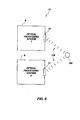
- FIG. 8 is a schematic representation of a system for stereophonically imaging objects in a liquid environment, in accordance with an embodiment of the present invention.
- FIG. 1 A system, camera and method of imaging objects in a liquid environment, such as water, is illustrated with reference to FIG. 1 .
- the various embodiments produce images by enabling direct optical imaging of the acoustic amplitude and phase of acoustic waves on a surface.
- Embodiments of the present invention enable full-field imaging and noncontacting ultrasonics for acoustical imaging in water or other liquids.
- embodiments of the present invention enable recording of acoustic motion on a plane at video frame rates by optical means similar to conventional optical cameras. Such an approach for imaging objects provides a high rate of measurement since an entire image may be recorded simultaneously.
- embodiments of the present invention do not present phasing of successive samples in a single image frame.
- embodiments of the present invention utilize advancements in the field of video imaging for continued improvements to the acoustic, imaging as disclosed herein.
- the system 10 for imaging underwater target objects may comprise an excitation source such as an acoustic source or ensonifier 100 .
- the ensonifier 100 is preferably configured to produce coherent continuous or tone burst mode acoustic waves at the desired frequency for ensonifying (i.e., illuminating with sound) the near vicinity of the target object and phase locked to the reference modulation placed on the optical phase modulator described later.
- the ensonifier 100 may take the form of a speaker or other more sophisticated acoustic source capable of generating a pressure or acoustic wavefront 102 .
- the acoustic wavefront 102 propagates and impinges upon a target object 104 which reflects at least a portion of the acoustic waves as reflected acoustic waves, illustrated as reflected acoustic wavefront 106 .
- the reflected acoustic waves may propagate directly to a pressure sensitive screen 12 or may optionally encounter an intermediate wave conditioning means.
- One such wave conditioning means within an embodiment of system 10 may include an acoustic lens 108 which acoustically modifies reflected acoustic wavefront 106 into refracted acoustic wavefront 110 .
- the acoustic lens 108 collects the reflected acoustic waves reflected from the target object and focuses them as an acoustic image.
- Acoustic lens 108 may provide acoustic focusing of the reflected acoustic wavefront prior to the wavefront impinging upon screen 12 .
- the functionality of acoustic lens 108 is appreciated by those of ordinary skill in the art and is not further discussed herein.
- the acoustic imaging screen 12 serves to collect the reflected acoustic waves and converts the local acoustic pressure into a corresponding pattern of vibrations (e.g., deformations) on the screen.
- the deformation from the acoustic side 14 couples to the second or optical side 16 and exhibits a corresponding deformation.
- the screen 12 locally deforms from the local pressure gradients in the acoustic wave.
- the screen 12 is preferably compliant so as to minimally alter or influence the acoustic waves.
- screen 12 is preferably of a thickness much less than the wavelength of the acoustic waves being sensed or are of interest. For example, if the acoustic waves are about 1 mm long for a particular application, screen 12 ideally, but not necessarily, would be much less than about 1 mm in thickness.
- the optical side may be optimized for optical efficiency by making it retroreflective or by shaping it into a curve that may reflect the optical object beam more efficiently back to the optical imaging lens on the optical side.
- the screen, or membrane, 12 is preferably comprised of a material that minimizes dampening of the deformation between the acoustic side 14 and the optical side 16 . Furthermore, the screen 12 preferably is comprised of a material that is compliant to further minimize alterations to the reflected wavefront passing through the screen from the acoustic side 14 to the optical side 16 . Screen 12 and subsequently described alternative embodiments thereof, may be made of materials such as commercially available thin polymers, plastics, cloths, and even metals. A thin screen with holes much smaller than the acoustic wavelengths of interest will let fluid pass there through for pressure balancing. Furthermore, screens may serve as a phase separation boundary between two immiscible fluids.
- Screen 12 preferably reflect light, so such screens, or membranes, may be coated with a metal or some other appropriately reflective material which effectively reflect the optical wavelength of interest.
- the optical-side screen displacement induced in the screen 12 by the ensonifier 100 is detected and imaged with the aid of a photorefractive imaging system 21 .
- the photorefractive imaging system 21 may comprise a light source assembly 22 which produces two mutually coherent light beams or wavefronts: an object beam or wavefront 24 and a reference beam or wavefront 26 .
- An optical beam confining and directing device 28 operatively associated with the object beam 24 spreads and directs the object beam 24 onto the screen 12 as an expanded object beam 30 .
- beam 30 would be made collinear with beam 34 through the use of a polarizing beam splitter between items 78 and 80 , as is well known by those in the optics field.
- the expanded object beam 30 illuminates a two-dimensional area or region 32 on the screen 12 . Thereafter, the screen 12 modulates the phase of the expanded object wavefront or beam 30 to form a phase modulated object wavefront or beam 34 .
- the reference beam or wavefront 26 produced by the light source assembly 22 is directed through a optical beam phase modulator 36 to produce a modulated reference beam 38 .
- the beam modulator 36 modulates the phase of the reference beam 26 at a frequency that is slightly different than the frequency of the optical-side screen displacement frequency sought to be detected on the screen 12 .
- the modulated reference beam or wavefront 38 is then directed toward a sensing medium 40 wherein the modulated reference beam 38 is combined with the modulated object beam 34 reflected by the screen 12 .
- the sensing medium 40 may comprise a photorefractive material, such as a bismuth silicon oxide crystal.
- photorefractive refers to those materials wherein the space charge electrical grating can be either in-phase or out-of-phase with the optical interference pattern.
- the space charge field modulates the local refractive index of the sensing medium 40 (via the electro-optical effect), creating a diffraction grating within the sensing medium 40 that embodies the static and low-frequency phase information between the object and reference optical beams.
- the result is the formation of a hologram (not shown) which may be used to reconstruct an image, through the well known 2-wave or 4-wave mixing process, of the desired elastic wave displacement distribution operating, usually, at a higher frequency on the screen 12 through the heterodyne mixing operation occurring within the photorefractive material.
- the intensity variations of the reconstructed image are approximately proportional to the higher frequency phase differences between the modulated object and reference beams 34 and 38 , respectively, for phase differences less than approximately 0.1 radian.
- the reading-out of the hologram to reconstruct the image of the acoustic wave can be performed by the same light source as indicated in FIG. 1 for the out-of-phase gratings.
- a separate independent light source at a different wavelength may be used by employing the appropriate Bragg angle to reconstruct the image of the ultrasonic wave.
- the photorefractive material comprising the sensing medium 40 has a limited response time, i.e., cut-off frequency. Consequently, the photorefractive sensing medium 40 will not record interference patterns having frequencies above the cut-off frequency of the sensing medium 40 .
- the reference beam 26 is modulated at a frequency that is very close to, but not the same as, the frequency of the deformation of the reflected acoustic wavefront in the screen 12 , and since the difference between the frequencies is optimally less than the cut-off frequency of the photorefractive sensing medium 40 , the image reconstructed from the hologram (not shown) produced by the photorefractive sensing medium 40 moves at a speed that is related to the frequency difference between the modulated object beam 34 and the modulated reference beam 38 .
- the photorefractive sensing medium 40 since the cut-off frequency of the photorefractive sensing medium 40 is generally lower than the acoustic wave frequency, the photorefractive sensing medium 40 will not record disturbances and waves if the frequencies of the disturbances and waves are such that the differences between those frequencies and the frequency of the modulated reference beam are greater than the cut-off frequency of the photorefractive sensing medium 40 . Stated simply; the photorefractive sensing medium 40 functions as a mixer and as a low pass filter, recording only those interference patterns having frequencies less than the cut-off frequency of the photorefractive sensing medium 40 .
- the image reconstructed from the hologram produced within the photorefractive sensing medium 40 may be detected by suitable array (i.e., two-dimensional) detector 42 , such as a video camera 44 .
- a video camera 44 may be directly observed by the human eye via an eyepiece (not shown) or other such device.
- the video camera 44 may be connected to a display device 46 , such as a CRT or LCD panel, suitable for displaying the reconstructed image.
- a display device 46 such as a CRT or LCD panel
- display device 46 may further include portable or wearable displays that allow a user to view the optical image in stereo, or in the case of a single optical processing system 8 , allows the user to view the optical image on a portable display device 46 .
- the image captured by the video camera 44 may be recorded on a suitable medium (e.g., video tape) for later playback and/or analysis.
- the system 10 includes a “dry side” and a “wet side” partitioned by an illustrative isolation boundary wherein various portions of the apparatus reside and method is performed.
- a combination of two separate embodiments are illustrated with respect to FIG. 1 , namely the reflected acoustic waves may propagate directly to a pressure sensitive screen 12 or may optionally encounter an intermediate wave conditioning means.
- system 10 exposes screen 12 directly to the pressure waves of reflected acoustic wavefront 106 .
- the wet side is partitioned separate from the dry side by an isolation boundary 114 which is implemented as a physical boundary.
- optical processing system 8 is included on the dry side while the remaining underwater environment becomes the wet side of the system. Due to harsh environmental concerns with respect to the present embodiment, screen 12 should be resilient and address conditions relating to the mobility of optical processing system 8 and the acoustical artifacts further relating thereto.
- system 10 further includes an acoustic lens 108 which provides acoustical focusing of the reflected acoustic wavefront prior to their arrival at screen 12 .
- the cavity or region 116 formed by the addition of acoustic lens 108 to the system 10 is preferably filled with a fluid capable of propagating the lens-modified reflected acoustic wavefront to screen 12 .
- the photorefractive imaging system 21 may comprise a photorefractive imaging system of the type shown and described in U.S. Pat. No. 6,175,411 entitled “Apparatus and Method for Measuring and Imaging Traveling Waves” of Telschow and Deason, which is incorporated herein by reference.
- the photorefractive imaging system 21 may comprise a light source assembly 22 which produces two mutually coherent light beams or wavefronts: An object beam or wavefront 24 and a reference beam or wavefront 26 .
- the object and reference beams 24 and 26 are preferably derived from a single, coherent source beam 64 produced by the light source assembly 22 .
- the light source assembly 22 which may be used to generate the single, coherent source beam 64 may comprise any of a wide range of lasers that are now known in the art or that may be developed in the future that would be suitable for producing such a coherent source beam 64 .
- the light source 22 may comprise a 100 milliwatt (mw) frequency doubled, diode pumped solid state laser having a wavelength of 532 nm, such as a Coherent Verdi® laser available from Coherent, Inc. of Santa Clara, Calif.
- mw milliwatt
- the source beam 64 produced by the light source assembly 22 first may be directed through a halfwave plate 66 before being directed to a beam splitter 68 which splits the source beam 64 into the object beam 24 and the reference beam 26 . Thereafter the object beam 24 may be directed to a beam confining and directing device 28 which directs the object beam 24 onto the screen 12 as an expanded object beam 30 . While any of a wide (range of components or combinations of components may be used to direct the object beam 24 onto the screen 12 , in one exemplary embodiment, the beam directing device 28 may comprise a beam expansion lens 70 . Such an arrangement converts the object beam 24 into an expanded, generally cone-shaped beam 30 and allows the expanded beam 30 to be conveniently directed onto the desired portion of the screen 12 to illuminate a two-dimensional area or region 32 thereof.
- beam splitter 68 and expanding lens assembly 70 for producing the expanded object beam 30 and for directing it onto the screen 12 may comprise any of a wide range components and devices that are well-known in the art and readily commercially available. Consequently, the particular beam splitter 68 and expanding lens assembly 70 which may be utilized in one exemplary embodiment of the present invention will not be described in further detail herein.
- the deforming screen 12 modulates the phase of the expanded object beam 30 to produce modulated object beam 34 . Thereafter, phase modulated object beam 34 is collected by a collection lens 78 which focuses the modulated object beam 34 onto the photorefractive sensing medium 40 .
- a polarizer 80 positioned between the collection lens 78 and the photorefractive sensing medium 40 may comprise a high extinction ratio polarizer to select one polarization component of the modulated object beam 34 for passage onto the photorefractive sensing medium 40 .
- the reference beam 26 emerging from the beam splitter 68 is directed through a beam modulator 36 which modulates the phase of the reference beam 26 to produce a modulated reference beam 38 .
- the beam modulator 36 comprises an electro-optic modulator of the type well-known in the art for modulating the phase of the reference beam 26 .
- a variable oscillator 76 of the type that is also well-known in the art and operatively associated with the beam modulator 36 allows the beam modulator 36 to modulate the phase of the reference beam 26 in a phase-locked manner and at a frequency that is slightly different than the frequency of the phase modulation of the modulated object beam 34 .
- variable oscillator 76 may be adjusted so that the beam modulator 36 modulates the phase of the reference beam at a frequency differing from the object wave modulation frequency by about, for example, 25 Hz.
- other frequencies may also be used as would be obvious to persons having ordinary skill in the art.
- the modulated reference beam 38 may be expanded by a suitable beam expander assembly 82 which, in one exemplary embodiment may comprise a pair of lenses 84 and 86 .
- Polarizer 88 may comprise a high extinction ratio polarizer of the type well known in the art and readily commercially available.
- the phase related features such as interference fringes produced by mixing of the object and reference beams of the reconstructed image will move at a speed that is related to the frequency difference between the modulated object beam 34 and the modulated reference beam 38 .
- the photorefractive material comprising the sensing medium 40 has an intrinsic response time (i.e., cut-off frequency)
- the offset or difference frequency between the modulated object and reference beams 34 and 38 must be below the cut-off frequency of the photorefractive material for improved results. If the difference frequency is too great, the resulting interference pattern will move so rapidly that the photorefractive material will fail to record the change.
- the bismuth silicon oxide material which may comprise the photorefractive sensing medium 40 in one embodiment of the present invention has a high frequency cut-off of about 67 Hz, that increases with optical power.
- photorefractive sensing media having other high frequency cut-offs e.g., high frequency cut-offs of about 1 kHz
- the reference beam 26 should be modulated at a frequency so that the difference frequency between the modulated reference beam 38 and the modulated object beam 34 does not exceed the high frequency cut-off of the photorefractive sensing medium 40 .
- variable oscillator 76 in one embodiment of the present invention is set to modulate the phase of the reference beam at a frequency that is about ⁇ 25 Hz from the frequency of the modulated object beam 34 .
- a frequency that is about ⁇ 25 Hz from the frequency of the modulated object beam 34 .
- the reference beam should be modulated at a frequency of about 100 kHz ⁇ 25 Hz.
- the holographically reconstructed image produced by the photorefractive sensing medium 40 may be observed by means of a suitable array (i.e., two-dimensional) detector 42 , such as a CCD-type video camera 44 .
- the image may by directly observed by the human eye via an eyepiece (not shown) or other such device.
- it will be desirable to adjust the thickness of the sensing medium 40 in order to achieve a 90° polarization shift between the diffracted modulated reference beam 38 and the transmitted modulated object beam 34 .
- Such a polarization shift enables the directly transmitted object beam 34 to be eliminated by a properly oriented polarizer 90 positioned between the detector 42 and photorefractive sensing medium 40 .
- an imaging lens 92 between the detector 42 and the photorefractive sensing medium 40 .
- the video camera 44 may be connected to a suitable display device 46 , such as a CRT monitor or LCD panel, suitable for displaying the image.
- a suitable display device 46 such as a CRT monitor or LCD panel
- the image captured by the video camera 44 may be recorded on a suitable medium (e.g., digital media or video tape) for later playback and/or analysis.
- a camera 120 embodies specific aspects of the system 10 of FIG. 1 .
- a camera 120 is illustrated as being configured in a portable submersible configuration suitable for imaging a target object 104 in an underwater application.
- Camera 120 may include an attached excitation source such as an acoustic source or ensonifier 122 .
- An ensonifier 122 may take the form of a speaker or other more sophisticated acoustic source capable of generating a pressure or acoustic wavefront 124 .
- the acoustic wavefront 124 propagates and impinges upon a target object 104 which reflects at least a portion of the acoustic waves in acoustic wavefront 124 as reflected acoustic waves, illustrated as acoustic wavefront 126 .
- ensonifier 122 may be detached from camera 120 as an independent acoustic wave source.
- camera 120 may rely upon manmade or natural acoustic or pressure wave-generating phenomenon for obtaining reflected acoustic waves, providing as long as suitable synchronization between the natural source and the reference beam modulation can be achieved.
- the camera 120 includes a housing 130 that is partitioned by an illustrative isolation boundary 136 into a dry side or region, generally illustrated as 132 , and a wet side or region, generally illustrated as 134 .
- a combination of two separate embodiments are illustrated with respect to FIG. 2 , namely the reflected acoustic waves 126 may propagate directly to a pressure sensitive screen 12 or may optionally encounter an intermediate wave conditioning means.
- camera 120 exposes screen 12 directly to the pressure waves of reflected acoustic wavefront 126 .
- the wet side 134 of camera 120 becomes the entire underwater environment.
- the camera 120 further includes an acoustic lens 108 which provides acoustical focusing of the reflected acoustic wavefront prior to their arrival at screen 12 .
- the cavity formed by the addition of acoustic lens 108 to camera 120 is preferably filled with a fluid capable of propagating the lens-modified reflected acoustic wavefront to screen 12 .
- the camera 120 of FIG. 2 further includes a screen 12 for relaying deformations received on the acoustic side 138 of screen 12 and propagating them to an optical side 140 of screen 12 .
- the specific composition of screen 12 may vary depending upon the environmental exposure of screen 12 .
- the camera 12 further comprises an optical processing system 8 for converting the acoustically-induced deformations from screen 12 into optical intensity images representative of the target object 104 .
- the specifics of the optical processing system 8 are described above and may include specific modifications for enhancing portability.
- the system 10 for imaging underwater target objects 104 may be operated according to the method 48 illustrated in FIG. 3 in order to image an underwater target object.
- the method ensonifies 50 a target object with acoustic waves projected as an acoustic wavefront bombarded about the target object.
- the target object reflects the acoustic wavefront as a reflected acoustic wavefront which further encounters and deforms 52 a first or acoustic side of a screen.
- the second or optical side of the screen is responsive to the deformation of the first side which results in a corresponding deformation.
- Subsequent processing generally converts 54 the acoustic waves as received at the screen 12 (FIG. 1 ), from their respective screen deformations into optical intensity images representative of the target object.
- the deformation of screen 12 modulates the phase of the expanded object beam 30 to form a modulated object beam 34 (FIG. 1 ).
- the phase of the reference beam or wavefront 26 is modulated 56 to produce a modulated reference beam 38 .
- the phase of the reference beam 26 is modulated at a frequency that is slightly different than the frequency of the acoustic wave that is to be detected.
- the modulated object beam 34 and modulated reference beam 38 are then combined 58 within the photorefractive sensing medium 40 which produces a hologram (not shown) from which may be reconstructed an image of the screen displacement on the optical side of the screen 12 .
- An optical intensity image is generated 60 as a result of the received acoustic wavefront.
- FIG. 4 illustrates one formation of the screen, in accordance with an embodiment of the present invention.
- the screen is illustrated as screen 12 ′ formed as a rigid screen configured to also function as an isolation boundary for separating the wet and dry sides when an acoustic lens 108 is not present or, alternatively, to function as the isolation barrier to the dry side when the acoustic lens 108 is utilized.
- screen 12 ′ is configured as a monolithic arrangement comprised of one of various suitable materials, an example of which may include glasses or plastics which facilitate deformation from an acoustic side to an optical side with minimization of dampening and fringe deformation about the acoustic image 94 as generated when the acoustic wavefront impinges upon the screen 12 ′.
- FIG. 5 illustrates a screen and acoustic lens in accordance with another embodiment of the present invention.
- the present embodiment integrates an acoustic lens and the screen by forming a screen 12 ′′ as a facet of an acoustic lens 108 ′. Integration of screen 12 ′′ with acoustic lens 108 ′ reduces the bulk and weight associated with system 10 and camera 120 .
- the acoustic image 94 is formed from the deformations resulting on screen 12 ′′ which may be optically processed by optical processing system 8 (FIG. 1 ).
- the screen may consist of a material specifically chosen to enhance the amplitude of the acoustic vibrations through proper choice of physical properties.
- FIG. 6 illustrates a screen implemented in accordance with yet another embodiment of the present invention.
- screen 12 ′′ is implemented as multiple layers configured to provide resiliency against a liquid application on the acoustic side.
- the acoustic screen 12 ′′ is comprised of an imaging screen 142 implemented as a pressure sensitive material which is further backed by pressure compensating liquid 144 .
- the pressure compensating liquid 144 neutralizes the pressure associated with the pressure associated with either the wetside liquid environment of the target object or, in the case of an acoustic lens 108 , the intermediate cavity between the acoustic lens 108 and the screen 12 ′′.
- Compensating liquid 144 may be any liquid such as water, oil, silicone liquids, or any other inert liquid.
- the screen 12 ′′ of the present embodiment is further backed by a rigid backplane 146 for coupling with the optical side of the system.
- FIG. 7 illustrates a screen implementation in accordance with yet a further embodiment of the present invention.
- screen 12 ′′′ is configured for improved optical efficiency by contouring the optical side 16 of screen 12 ′′ into a curve configuration to improve the optical reflectivity of the object beam back to the optical imaging lens in optical processing system 8 .
- FIG. 8 illustrates a stereoscopic system, in accordance with an embodiment of the present invention.
- a stereoscopic system 11 includes a plurality of optical processing systems 8 arranged to receive spatially-diverse reflected acoustic wavefronts 106 at separate screens 12 to generate separate optical intensity images of target object 104 . The resultant optical images may then be projected in display systems configured for stereophonic presentation to a user.
- both beams 106 could be demodulated by a single photorefractive element, with independent reconstructed images recorded by independent cameras.
- a significant advantage associated with the method and apparatus according to the present invention is that it provides an acoustic imaging means for imaging target objects in liquids that inhibit direct optical imaging techniques. While conventional optical only imaging techniques may have provided greater image resolution, the combination of acoustic and optical imaging is an advancement over acoustic-only imaging techniques.
- Another significant advantage of the present invention is that pixilation, meaning conversion from a continuous or analog form to a discrete or digitized form, occurs in the optical portion of the system rather than in the acoustic portion. Since spatial resolution of the image number of pixels in the optical or video camera, typically in the megapixel range, spacial resolutions of the object geometry are limited only by the acoustic wavelength employed. Because of the novel partitioning of the apparatus and method of the present invention, an improved resolution or pixelization is obtained thereby enabling improved imaging resolution.
Landscapes
- Physics & Mathematics (AREA)
- General Physics & Mathematics (AREA)
- Measurement Of Mechanical Vibrations Or Ultrasonic Waves (AREA)
Abstract
Description
Claims (23)
Priority Applications (1)
| Application Number | Priority Date | Filing Date | Title |
|---|---|---|---|
| US10/611,388 US6847584B2 (en) | 2003-06-30 | 2003-06-30 | Method and apparatus for acoustic imaging of objects in water |
Applications Claiming Priority (1)
| Application Number | Priority Date | Filing Date | Title |
|---|---|---|---|
| US10/611,388 US6847584B2 (en) | 2003-06-30 | 2003-06-30 | Method and apparatus for acoustic imaging of objects in water |
Publications (2)
| Publication Number | Publication Date |
|---|---|
| US20040264296A1 US20040264296A1 (en) | 2004-12-30 |
| US6847584B2 true US6847584B2 (en) | 2005-01-25 |
Family
ID=33541309
Family Applications (1)
| Application Number | Title | Priority Date | Filing Date |
|---|---|---|---|
| US10/611,388 Expired - Fee Related US6847584B2 (en) | 2003-06-30 | 2003-06-30 | Method and apparatus for acoustic imaging of objects in water |
Country Status (1)
| Country | Link |
|---|---|
| US (1) | US6847584B2 (en) |
Cited By (3)
| Publication number | Priority date | Publication date | Assignee | Title |
|---|---|---|---|---|
| US20060114748A1 (en) * | 2004-06-04 | 2006-06-01 | Hull Underwater Imaging Systems, Inc. | Underwater exterior ship hull imaging system employing a remote microprocessor controlled acoustic transducer array |
| US8820164B2 (en) | 2012-01-31 | 2014-09-02 | Sikorsky Aircraft Corporation | Retroreflector for ultrasonic inspection |
| WO2019119398A1 (en) * | 2017-12-22 | 2019-06-27 | Powervision Tech Inc. | Underwater drone with capacity of multi-shooting view |
Citations (14)
| Publication number | Priority date | Publication date | Assignee | Title |
|---|---|---|---|---|
| US3772457A (en) * | 1971-03-29 | 1973-11-13 | American Express Invest | Sonic image transducer using a storage camera |
| US3869904A (en) * | 1965-05-12 | 1975-03-11 | Columbia Broadcasting Syst Inc | Ultrasonic cameras |
| US3973235A (en) * | 1973-04-24 | 1976-08-03 | U.S. Philips Corporation | Device for the detection of an acoustic image |
| US4518992A (en) | 1982-11-17 | 1985-05-21 | Sonoscan, Inc. | Acoustic imaging system and method |
| US4905202A (en) * | 1987-12-28 | 1990-02-27 | Richard L. Scully | Detection panel and method for acoustic holography |
| US5262884A (en) * | 1991-10-09 | 1993-11-16 | Micro-Optics Technologies, Inc. | Optical microphone with vibrating optical element |
| US5986224A (en) | 1995-04-19 | 1999-11-16 | Elo Touchsystems, Inc. | Acoustic condition sensor employing a plurality of mutually non-orthogonal waves |
| US6134006A (en) | 1998-02-25 | 2000-10-17 | Becthel Bwxt Idaho, Llc | Imaging photorefractive optical vibration measurement method and device |
| US6175411B1 (en) | 1998-02-25 | 2001-01-16 | Bechtel Bwxt Idaho, Llc | Apparatus and method for measuring and imaging traveling waves |
| US6401540B1 (en) | 2000-02-29 | 2002-06-11 | Bechtel Bwxt Idaho, Llc | Method and apparatus for detecting internal structures of bulk objects using acoustic imaging |
| US6486962B1 (en) | 1998-07-08 | 2002-11-26 | Bechtel Bwxt Idaho, Llc | Method and apparatus for assessing material properties of sheet-like materials |
| US20030053373A1 (en) | 2001-09-17 | 2003-03-20 | Erikson Kenneth R. | Acoustical imaging interferometer for detection of buried underwater objects |
| US20030058738A1 (en) | 2001-09-17 | 2003-03-27 | Erikson Kenneth R. | Co-registered acoustical and optical cameras for underwater imaging |
| US6552841B1 (en) | 2000-01-07 | 2003-04-22 | Imperium Advanced Ultrasonic Imaging | Ultrasonic imager |
-
2003
- 2003-06-30 US US10/611,388 patent/US6847584B2/en not_active Expired - Fee Related
Patent Citations (14)
| Publication number | Priority date | Publication date | Assignee | Title |
|---|---|---|---|---|
| US3869904A (en) * | 1965-05-12 | 1975-03-11 | Columbia Broadcasting Syst Inc | Ultrasonic cameras |
| US3772457A (en) * | 1971-03-29 | 1973-11-13 | American Express Invest | Sonic image transducer using a storage camera |
| US3973235A (en) * | 1973-04-24 | 1976-08-03 | U.S. Philips Corporation | Device for the detection of an acoustic image |
| US4518992A (en) | 1982-11-17 | 1985-05-21 | Sonoscan, Inc. | Acoustic imaging system and method |
| US4905202A (en) * | 1987-12-28 | 1990-02-27 | Richard L. Scully | Detection panel and method for acoustic holography |
| US5262884A (en) * | 1991-10-09 | 1993-11-16 | Micro-Optics Technologies, Inc. | Optical microphone with vibrating optical element |
| US5986224A (en) | 1995-04-19 | 1999-11-16 | Elo Touchsystems, Inc. | Acoustic condition sensor employing a plurality of mutually non-orthogonal waves |
| US6134006A (en) | 1998-02-25 | 2000-10-17 | Becthel Bwxt Idaho, Llc | Imaging photorefractive optical vibration measurement method and device |
| US6175411B1 (en) | 1998-02-25 | 2001-01-16 | Bechtel Bwxt Idaho, Llc | Apparatus and method for measuring and imaging traveling waves |
| US6486962B1 (en) | 1998-07-08 | 2002-11-26 | Bechtel Bwxt Idaho, Llc | Method and apparatus for assessing material properties of sheet-like materials |
| US6552841B1 (en) | 2000-01-07 | 2003-04-22 | Imperium Advanced Ultrasonic Imaging | Ultrasonic imager |
| US6401540B1 (en) | 2000-02-29 | 2002-06-11 | Bechtel Bwxt Idaho, Llc | Method and apparatus for detecting internal structures of bulk objects using acoustic imaging |
| US20030053373A1 (en) | 2001-09-17 | 2003-03-20 | Erikson Kenneth R. | Acoustical imaging interferometer for detection of buried underwater objects |
| US20030058738A1 (en) | 2001-09-17 | 2003-03-27 | Erikson Kenneth R. | Co-registered acoustical and optical cameras for underwater imaging |
Cited By (4)
| Publication number | Priority date | Publication date | Assignee | Title |
|---|---|---|---|---|
| US20060114748A1 (en) * | 2004-06-04 | 2006-06-01 | Hull Underwater Imaging Systems, Inc. | Underwater exterior ship hull imaging system employing a remote microprocessor controlled acoustic transducer array |
| US7072244B2 (en) * | 2004-06-04 | 2006-07-04 | Hull Underwater Imaging Systems, Inc. | Underwater exterior ship hull imaging system employing a remote microprocessor controlled acoustic transducer array |
| US8820164B2 (en) | 2012-01-31 | 2014-09-02 | Sikorsky Aircraft Corporation | Retroreflector for ultrasonic inspection |
| WO2019119398A1 (en) * | 2017-12-22 | 2019-06-27 | Powervision Tech Inc. | Underwater drone with capacity of multi-shooting view |
Also Published As
| Publication number | Publication date |
|---|---|
| US20040264296A1 (en) | 2004-12-30 |
Similar Documents
| Publication | Publication Date | Title |
|---|---|---|
| Ishikawa et al. | High-speed imaging of sound using parallel phase-shifting interferometry | |
| US4012951A (en) | Acoustic examination methods and apparatus | |
| US4338821A (en) | Liquid crystal cell for acoustical imaging | |
| US5555128A (en) | Phase coding technique for one-way image transmission through an aberrating medium | |
| US3745812A (en) | Acoustic imaging apparatus | |
| WO2017098343A1 (en) | System, apparatus and method for monitoring of surface profile and thickness measurement in thin films | |
| AU2007250514B2 (en) | Remote sensing of underwater acoustic fields | |
| US3670098A (en) | Optical scanning apparatus | |
| FR2566140A1 (en) | DEVICE FOR ANALYZING AND CORRECTING REAL-TIME WAVE SURFACES WITH A POLARIZED INTERFEROMETER | |
| US6134006A (en) | Imaging photorefractive optical vibration measurement method and device | |
| CN103635784A (en) | Photoacoustic vibration meter | |
| Ishikawa et al. | Optical sensing of sound fields: Non-contact, quantitative, and single-shot imaging of sound using high-speed polarization camera | |
| US6401540B1 (en) | Method and apparatus for detecting internal structures of bulk objects using acoustic imaging | |
| US5684588A (en) | Homodyne and hetrodyne imaging in a light scattering medium | |
| US6847584B2 (en) | Method and apparatus for acoustic imaging of objects in water | |
| Telschow et al. | Direct imaging of traveling Lamb waves in plates using photorefractive dynamic holography | |
| US4905202A (en) | Detection panel and method for acoustic holography | |
| US6353576B1 (en) | Detector in ultrasonic holography | |
| US3831135A (en) | Optical imaging of sound fields by heterodyning | |
| IL45787A (en) | Acousto-optical transducer | |
| Kessler | Imaging with dynamic-ripple diffraction | |
| US3594717A (en) | Sonic transducer | |
| US3706965A (en) | Real-time acoustic imaging system | |
| US3636248A (en) | Acoustical holography by optically sampling a sound field in bulk | |
| US6831874B2 (en) | Ultrasonic holography detector |
Legal Events
| Date | Code | Title | Description |
|---|---|---|---|
| AS | Assignment |
Owner name: BECHTELL BWXT IDAHO, LLC, IDAHO Free format text: ASSIGNMENT OF ASSIGNORS INTEREST;ASSIGNORS:DEASON, VANCE A.;TELSCHOW, KENNETH L.;REEL/FRAME:014723/0698 Effective date: 20031104 |
|
| AS | Assignment |
Owner name: ENERGY, UNITED STATES DEPARTMENT OF, DISTRICT OF C Free format text: CONFIRMATORY LICENSE;ASSIGNOR:BECHTEL BWXT IDAHO, LLC;REEL/FRAME:014899/0579 Effective date: 20031216 |
|
| AS | Assignment |
Owner name: BATTELLE ENERGY ALLIANCE, LLC, IDAHO Free format text: ASSIGNMENT OF ASSIGNORS INTEREST;ASSIGNOR:BECHTEL BWXT IDAHO, LLC;REEL/FRAME:016226/0765 Effective date: 20050201 Owner name: BATTELLE ENERGY ALLIANCE, LLC,IDAHO Free format text: ASSIGNMENT OF ASSIGNORS INTEREST;ASSIGNOR:BECHTEL BWXT IDAHO, LLC;REEL/FRAME:016226/0765 Effective date: 20050201 |
|
| FPAY | Fee payment |
Year of fee payment: 4 |
|
| REMI | Maintenance fee reminder mailed | ||
| LAPS | Lapse for failure to pay maintenance fees | ||
| STCH | Information on status: patent discontinuation |
Free format text: PATENT EXPIRED DUE TO NONPAYMENT OF MAINTENANCE FEES UNDER 37 CFR 1.362 |
|
| FP | Lapsed due to failure to pay maintenance fee |
Effective date: 20130125 |