EP0010279B1 - Batteriegespeiste Leuchte - Google Patents
Batteriegespeiste Leuchte Download PDFInfo
- Publication number
- EP0010279B1 EP0010279B1 EP79103954A EP79103954A EP0010279B1 EP 0010279 B1 EP0010279 B1 EP 0010279B1 EP 79103954 A EP79103954 A EP 79103954A EP 79103954 A EP79103954 A EP 79103954A EP 0010279 B1 EP0010279 B1 EP 0010279B1
- Authority
- EP
- European Patent Office
- Prior art keywords
- battery
- lantern
- terminals
- axis
- plate
- Prior art date
- Legal status (The legal status is an assumption and is not a legal conclusion. Google has not performed a legal analysis and makes no representation as to the accuracy of the status listed.)
- Expired
Links
- 230000006835 compression Effects 0.000 description 5
- 238000007906 compression Methods 0.000 description 5
- 241001465382 Physalis alkekengi Species 0.000 description 3
- 239000003708 ampul Substances 0.000 description 1
- 238000010276 construction Methods 0.000 description 1
- 210000005069 ears Anatomy 0.000 description 1
- 238000000605 extraction Methods 0.000 description 1
- 238000010101 extrusion blow moulding Methods 0.000 description 1
- 238000004519 manufacturing process Methods 0.000 description 1
- 238000000034 method Methods 0.000 description 1
- BASFCYQUMIYNBI-UHFFFAOYSA-N platinum Chemical compound [Pt] BASFCYQUMIYNBI-UHFFFAOYSA-N 0.000 description 1
Images


Classifications
-
- F—MECHANICAL ENGINEERING; LIGHTING; HEATING; WEAPONS; BLASTING
- F21—LIGHTING
- F21L—LIGHTING DEVICES OR SYSTEMS THEREOF, BEING PORTABLE OR SPECIALLY ADAPTED FOR TRANSPORTATION
- F21L2/00—Systems of electric lighting devices
Definitions
- the invention relates to a lantern powered by an electric battery comprising a housing with two superposed compartments separated by a plate which carries on its upper face a bulb and on its lower face a central connection and an eccentric connection connected respectively to the socket and base of the bulb, the battery being mounted in the lower compartment in a rotatable manner around the vertical axis of the lantern, so that the eccentric connection is in contact with one of the terminals of the battery in a rotary position and does not in another.
- Such a lantern is known, for example from document GB-A-1216139. It has a closed box, with two superimposed compartments, the upper compartment containing a bulb and the lower compartment an electric battery.
- the two compartments of the housing are coaxial and movable in rotation with respect to each other and the bulb can be turned on or off by relative movement of the two compartments of the housing.
- the object of the present invention is to produce a lantern comprising switch means which are more difficult to detect by an uninitiated person.
- a lantern as specified above, which is characterized in that the battery is provided with an insulating plate which carries said terminals and which comprises at least one ear projecting laterally relative to to the stack, the internal face of the lower compartment comprising at least one vertical longitudinal groove extended at its upper part, by means of a boss, by a portion of horizontal plane, so that each ear cooperates with one of said vertical grooves for a first guide of the stack along the vertical axis for the introduction of the stack into the housing and, after passing over the boss, is supported by its underside on said plane portion for a second guide of the battery during its rotational movement around said axis, up to a stop corresponding to the contacting of said terminals and of said connections.
- the invention therefore makes use of a technique for fixing the battery in the housing, which can be called a “bayonet fixing” and which is in itself known in the field of lanterns, for example from document DE-C- 512 589.
- a technique for fixing the battery in the housing which can be called a “bayonet fixing” and which is in itself known in the field of lanterns, for example from document DE-C- 512 589.
- This is a simple mechanical fixing, the electrical switching of the bulb being ensured by other means.
- This document therefore gives no instruction for switching the bulb by means not visible from the outside.
- the edge of said ear can be indented and slide on a longitudinal rib internal to the housing and parallel to said axis.
- the second guidance is carried out by rotation of the stack around the axis, the underside of the ear coming to rest on a portion of plane orthogonal to the axis, and the springs being in a state of low compression.
- the ear can slide on the plane portion up to a stop corresponding to the contacting of said bulb connections and of the two battery terminals.
- the bulb is turned off and the battery is removed from the housing by reverse operations.
- the lantern according to the invention preferably comprises a unitary housing which does not reveal any switching means. Only an initiated person will guide the stack as specified above.
- the unitary housing of the lantern according to the invention and its internal guide means can easily be made of plastic by extrusion blow molding. This results in significant manufacturing savings.
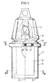
- the lantern appearing in FIG. 1 comprises a plastic casing 1, having a general shape of revolution around a vertical axis 2, and open at its lower end 3.
- This casing is divided by an intermediate plate 6 into two compartments 4 and 5 superimposed.
- the upper compartment 4 contains an electric bulb 7 fixed on the upper face of the plate 6.
- the lower compartment 5 contains a battery or a battery of batteries 8 having on its upper face an insulating plate 9 carrying two terminals 10 and 11. These two terminals are constituted by springs, one of which, the spring 10, is located in the center of plate 9 and on axis 2.
- the terminals 10 and 11 are intended to be brought into contact respectively with electrical connections 14 and 15 carried by the lower face 13 of the plate 6 and connected respectively in a known manner to the socket. and on the base of the bulb 7.
- the plate 9 of the stack 8 comprises two ears 16 and 17 diametrically opposite.
- the ear 16 has a notch 18 for guidance and indexing capable of sliding on a rib, re 19 of the internal face of the compartment 5, this rib being longitudinal and parallel to the axis 2.
- the ear 17 can, as to it, slide in a groove 20 of the internal face of the compartment 5, also longitudinal groove and parallel to the axis 2.
- the internal face of the compartment 5 further comprises a boss 21 located at a level higher than that of the end face 22 of the rib 19, a first portion of plane 23 orthogonal to the axis 2, located at a level lower than that of the boss 21, and a second portion of plane 24 symmetrical of the first portion 23 relative to the axis 2 ; finally it has two rib-shaped stops 25 and 26.
- the extraction of the stack then requires compression of the springs 10 and 11 to allow the passage of the ear 16 above the boss 21, then a longitudinal guidance along the rib 19.
Landscapes
- Engineering & Computer Science (AREA)
- General Engineering & Computer Science (AREA)
- Battery Mounting, Suspending (AREA)
- Non-Portable Lighting Devices Or Systems Thereof (AREA)
- Arrangement Of Elements, Cooling, Sealing, Or The Like Of Lighting Devices (AREA)
Claims (3)
Applications Claiming Priority (2)
| Application Number | Priority Date | Filing Date | Title |
|---|---|---|---|
| FR7829903 | 1978-10-20 | ||
| FR7829903A FR2439355A1 (fr) | 1978-10-20 | 1978-10-20 | Lanterne alimentee par une pile electrique |
Publications (2)
| Publication Number | Publication Date |
|---|---|
| EP0010279A1 EP0010279A1 (de) | 1980-04-30 |
| EP0010279B1 true EP0010279B1 (de) | 1983-06-01 |
Family
ID=9213981
Family Applications (1)
| Application Number | Title | Priority Date | Filing Date |
|---|---|---|---|
| EP79103954A Expired EP0010279B1 (de) | 1978-10-20 | 1979-10-15 | Batteriegespeiste Leuchte |
Country Status (8)
| Country | Link |
|---|---|
| US (1) | US4286310A (de) |
| EP (1) | EP0010279B1 (de) |
| CA (1) | CA1125250A (de) |
| DE (1) | DE2965579D1 (de) |
| DK (1) | DK442479A (de) |
| ES (1) | ES253441Y (de) |
| FR (1) | FR2439355A1 (de) |
| PT (1) | PT70336A (de) |
Families Citing this family (16)
| Publication number | Priority date | Publication date | Assignee | Title |
|---|---|---|---|---|
| GB2091863B (en) * | 1981-01-28 | 1985-06-05 | Freezinhot Bottle Co Ltd | Torch |
| US4428034A (en) | 1981-12-17 | 1984-01-24 | Tildawn Electronics Ltd. | Light bulb mounting unit |
| US4800469A (en) * | 1987-11-23 | 1989-01-24 | Leon Thomas B | Wheel mounted safety light |
| US5136475A (en) * | 1990-10-29 | 1992-08-04 | Mcdermott Kevin | Emergency light for marking of aircraft landing sites and other purposes |
| US5521595A (en) * | 1992-12-14 | 1996-05-28 | Totten; George L. | Illuminated hazard warning device |
| US5379200A (en) * | 1993-12-29 | 1995-01-03 | Echard; Terry P. | Portable electric lantern apparatus |
| US6030094A (en) * | 1998-05-01 | 2000-02-29 | The Coleman Company, Inc. | Collapsible lantern with automatic shut-off feature |
| US6685337B2 (en) | 2001-06-22 | 2004-02-03 | Garry W. Klees | Combination flashlight and candle lantern |
| USD488575S1 (en) | 2002-11-15 | 2004-04-13 | Carlos Aguilera | Portable fire hydrant lantern and nightlight |
| AU2006294402B2 (en) * | 2005-09-26 | 2010-07-22 | Neoz Pty Ltd | Lamp system particularly for cordless lamps |
| US7934849B2 (en) * | 2005-09-26 | 2011-05-03 | Neoz Pty Ltd | Rechargeable lamp system with lamp unit and docking station |
| US7635195B2 (en) * | 2006-11-21 | 2009-12-22 | The Coleman Company, Inc. | Headlamp that is convertible to a lantern |
| US20120212941A1 (en) * | 2011-02-22 | 2012-08-23 | Jomar Reschreiter | Cordless, portable, rechargeable food heating lamp |
| US9909726B2 (en) | 2013-12-12 | 2018-03-06 | The Coleman Company, Inc. | Battery life extender for portable lighting |
| WO2018026973A1 (en) * | 2016-08-02 | 2018-02-08 | Barebones Systems, Llc | Beacon pendant light |
| USD851810S1 (en) | 2018-02-07 | 2019-06-18 | Barebones Systems, Llc | Pendant light |
Family Cites Families (3)
| Publication number | Priority date | Publication date | Assignee | Title |
|---|---|---|---|---|
| DE512589C (de) * | 1929-11-14 | 1930-11-14 | Friemann & Wolf G M B H | Elektrische Handlampe |
| US3087052A (en) * | 1960-08-19 | 1963-04-23 | Electric Storage Battery Co | Hand lantern construction |
| GB1216139A (en) * | 1968-10-10 | 1970-12-16 | Per Neesbye-Hansen | Improvements in or relating to electric battery lanterns |
-
1978
- 1978-10-20 FR FR7829903A patent/FR2439355A1/fr active Granted
-
1979
- 1979-09-25 US US06/078,677 patent/US4286310A/en not_active Expired - Lifetime
- 1979-10-15 DE DE7979103954T patent/DE2965579D1/de not_active Expired
- 1979-10-15 EP EP79103954A patent/EP0010279B1/de not_active Expired
- 1979-10-18 PT PT70336A patent/PT70336A/pt unknown
- 1979-10-19 DK DK442479A patent/DK442479A/da not_active Application Discontinuation
- 1979-10-19 CA CA338,059A patent/CA1125250A/fr not_active Expired
- 1979-10-19 ES ES1979253441U patent/ES253441Y/es not_active Expired
Also Published As
| Publication number | Publication date |
|---|---|
| CA1125250A (fr) | 1982-06-08 |
| DK442479A (da) | 1980-04-21 |
| ES253441Y (es) | 1981-10-16 |
| ES253441U (es) | 1981-04-01 |
| EP0010279A1 (de) | 1980-04-30 |
| FR2439355B1 (de) | 1981-02-27 |
| DE2965579D1 (en) | 1983-07-07 |
| FR2439355A1 (fr) | 1980-05-16 |
| US4286310A (en) | 1981-08-25 |
| PT70336A (fr) | 1979-11-01 |
Similar Documents
| Publication | Publication Date | Title |
|---|---|---|
| EP0010279B1 (de) | Batteriegespeiste Leuchte | |
| EP1322210B1 (de) | Mittels eines drehbaren deckels geschlossenes kochgefäss | |
| EP0409744B1 (de) | Behälter für elektrische, zylindrische Batterien mit verschiedenen Durchmessern | |
| EP1734849B1 (de) | Elektrisches gerät zum erhitzen von flüssigkeit | |
| WO2015059163A1 (fr) | Ensemble de prises electriques | |
| EP0554171A1 (de) | Bürstenhalter für einen elektrischen Motor mit drehbarem Kollektor | |
| EP0135409B1 (de) | Sicherheitsvorrichtung für einen elektrischen Apparat mit aufladbarem Akkumulator | |
| EP0004503B1 (de) | Taschenlampengehäuse | |
| CH660257A5 (fr) | Porte-fusible. | |
| EP0193045B1 (de) | Elektrischer Uhren-Modul, ausgelegt zur Anpassung der Batterie-polarität an diejenige der Schaltung | |
| CH591767A5 (en) | Cylindrical primary cell with deformable washer in base - engages threaded cap on centre electrode of second cell to hold both together in series connection | |
| FR2922052A1 (fr) | Prise de courant enfichable comportant un corps de prise ouvrable et un bloc de connexion mobile a pivotement | |
| EP0236649A1 (de) | Elektrische Lampe, insbesondere Taschenlampe | |
| EP4078641A1 (de) | Mechanismus für einen elektrischen schalter, elektrische baugruppe und elektrischer schalter dafür | |
| JPS6026781Y2 (ja) | 小型電気機器 | |
| FR2594604A1 (fr) | Systeme de contact electrique embrochable | |
| EP0840058A1 (de) | Tragbare elektrische Lampe mit einer rotierbaren Trommel | |
| FR2634966A1 (fr) | Magasin universel porte-batteries pour l'alimentation electrique d'un appareil electroportatif | |
| FR2914790A1 (fr) | Prise de courant a double configuration d'alimentation | |
| FR2578103A1 (fr) | Boite a piles, notamment a usage militaire | |
| FR2771848A1 (fr) | Interrupteur electrique pouvant realiser plusieurs fonctions , par exemple les fonctions poussoir, va et vient,avec les memes pieces de base | |
| WO2024022681A1 (fr) | Module de coupure électrique avec barrière diélectrique | |
| FR2538503A1 (en) | Illuminating device for the forehead. | |
| EP0662584A1 (de) | Lampenfassung und Taschenlampe mit einer solchen Fassung | |
| JP3201630B2 (ja) | 電気かみそり |
Legal Events
| Date | Code | Title | Description |
|---|---|---|---|
| PUAI | Public reference made under article 153(3) epc to a published international application that has entered the european phase |
Free format text: ORIGINAL CODE: 0009012 |
|
| AK | Designated contracting states |
Designated state(s): BE CH DE FR GB IT LU NL |
|
| 17P | Request for examination filed | ||
| ITF | It: translation for a ep patent filed | ||
| GRAA | (expected) grant |
Free format text: ORIGINAL CODE: 0009210 |
|
| RAP1 | Party data changed (applicant data changed or rights of an application transferred) |
Owner name: GIPELEC S.A. |
|
| AK | Designated contracting states |
Designated state(s): BE CH DE FR GB IT LU NL |
|
| REF | Corresponds to: |
Ref document number: 2965579 Country of ref document: DE Date of ref document: 19830707 |
|
| PGFP | Annual fee paid to national office [announced via postgrant information from national office to epo] |
Ref country code: DE Payment date: 19830811 Year of fee payment: 5 |
|
| PGFP | Annual fee paid to national office [announced via postgrant information from national office to epo] |
Ref country code: CH Payment date: 19830815 Year of fee payment: 5 |
|
| PGFP | Annual fee paid to national office [announced via postgrant information from national office to epo] |
Ref country code: LU Payment date: 19830829 Year of fee payment: 5 |
|
| PGFP | Annual fee paid to national office [announced via postgrant information from national office to epo] |
Ref country code: BE Payment date: 19830831 Year of fee payment: 5 |
|
| PGFP | Annual fee paid to national office [announced via postgrant information from national office to epo] |
Ref country code: FR Payment date: 19830928 Year of fee payment: 5 |
|
| PG25 | Lapsed in a contracting state [announced via postgrant information from national office to epo] |
Ref country code: LU Free format text: LAPSE BECAUSE OF NON-PAYMENT OF DUE FEES Effective date: 19831031 |
|
| PGFP | Annual fee paid to national office [announced via postgrant information from national office to epo] |
Ref country code: NL Payment date: 19831031 Year of fee payment: 5 |
|
| PLBE | No opposition filed within time limit |
Free format text: ORIGINAL CODE: 0009261 |
|
| STAA | Information on the status of an ep patent application or granted ep patent |
Free format text: STATUS: NO OPPOSITION FILED WITHIN TIME LIMIT |
|
| 26N | No opposition filed | ||
| PG25 | Lapsed in a contracting state [announced via postgrant information from national office to epo] |
Ref country code: CH Effective date: 19841031 Ref country code: BE Effective date: 19841031 |
|
| BERE | Be: lapsed |
Owner name: GIPELEC S.A. Effective date: 19841015 |
|
| PG25 | Lapsed in a contracting state [announced via postgrant information from national office to epo] |
Ref country code: NL Effective date: 19850501 |
|
| GBPC | Gb: european patent ceased through non-payment of renewal fee | ||
| NLV4 | Nl: lapsed or anulled due to non-payment of the annual fee | ||
| PG25 | Lapsed in a contracting state [announced via postgrant information from national office to epo] |
Ref country code: FR Free format text: LAPSE BECAUSE OF NON-PAYMENT OF DUE FEES Effective date: 19850628 |
|
| REG | Reference to a national code |
Ref country code: CH Ref legal event code: PL |
|
| PG25 | Lapsed in a contracting state [announced via postgrant information from national office to epo] |
Ref country code: DE Effective date: 19850702 |
|
| REG | Reference to a national code |
Ref country code: FR Ref legal event code: ST |
|
| PG25 | Lapsed in a contracting state [announced via postgrant information from national office to epo] |
Ref country code: GB Effective date: 19881118 |