EP0010258A1 - Vorrichtung zur Vermeidung der Ansammlung von Fasern in einer Offenend-Spinnmaschine - Google Patents
Vorrichtung zur Vermeidung der Ansammlung von Fasern in einer Offenend-Spinnmaschine Download PDFInfo
- Publication number
- EP0010258A1 EP0010258A1 EP79103890A EP79103890A EP0010258A1 EP 0010258 A1 EP0010258 A1 EP 0010258A1 EP 79103890 A EP79103890 A EP 79103890A EP 79103890 A EP79103890 A EP 79103890A EP 0010258 A1 EP0010258 A1 EP 0010258A1
- Authority
- EP
- European Patent Office
- Prior art keywords
- presser
- roller
- combing
- feed roller
- open
- Prior art date
- Legal status (The legal status is an assumption and is not a legal conclusion. Google has not performed a legal analysis and makes no representation as to the accuracy of the status listed.)
- Granted
Links
- 238000007383 open-end spinning Methods 0.000 title claims abstract description 24
- 238000009825 accumulation Methods 0.000 title claims abstract description 17
- 239000000835 fiber Substances 0.000 claims abstract description 59
- 238000009987 spinning Methods 0.000 claims abstract description 12
- 238000004904 shortening Methods 0.000 abstract 1
- 238000010276 construction Methods 0.000 description 3
- 230000015556 catabolic process Effects 0.000 description 2
- 230000002950 deficient Effects 0.000 description 2
- 238000006731 degradation reaction Methods 0.000 description 2
- 239000000428 dust Substances 0.000 description 2
- 210000001520 comb Anatomy 0.000 description 1
- 230000003247 decreasing effect Effects 0.000 description 1
- 230000000694 effects Effects 0.000 description 1
- 239000012535 impurity Substances 0.000 description 1
- 238000004804 winding Methods 0.000 description 1
Images
Classifications
-
- D—TEXTILES; PAPER
- D01—NATURAL OR MAN-MADE THREADS OR FIBRES; SPINNING
- D01H—SPINNING OR TWISTING
- D01H4/00—Open-end spinning machines or arrangements for imparting twist to independently moving fibres separated from slivers; Piecing arrangements therefor; Covering endless core threads with fibres by open-end spinning techniques
- D01H4/30—Arrangements for separating slivers into fibres; Orienting or straightening fibres, e.g. using guide-rolls
- D01H4/32—Arrangements for separating slivers into fibres; Orienting or straightening fibres, e.g. using guide-rolls using opening rollers
Definitions
- the present invention relates to an open-end spinning frame and, more specifically, to a device for preventing the accumulation of fibers in an open-end spinning frame.
- the present invention more particularly, relates to a device for preventing fibers or flies, which are scattered from a combing roller in an open-end spinning frame, from accumulating in the region neighboring the upper and lower surfaces of a fiber feeding mechanism which is constructed with a feed roller for feeding fibers to the combing roller and a presser urged toward the feed roller.
- the accumulation of fibers may prevent the smooth spinning operation and may cause yarn breakage and defective spun yarn. Therefore, it is advantageous to prevent such an accumulation of fibers. It is generally observed that when the spinning speed in an open-end frame is increased, the accumulation of fibers in the region neighboring the upper and lower surfaces of a fiber feeding mechanism is greater.
- a device for preventing the accumulation of fibers in an open-end spinning frame is disclosed in United States Patent No. 3,922,839.
- the device is intended to prevent the accumulation of fibers in the space between the free lateral surfaces of the feed roller and the combing roller and the inner surface of the closure plate covering the feed roller and combing roller in an open-end spinning frame.
- a groove is formed on the inner surface of the closure plate extending in opposition to at least the free lateral surfaces of the feed roller and combing roller, and one end of the groove is connected to an air suction source, which is either a channel for feeding combed fibers to the rotary spinning chamber, or a duct which discharges the air exhausted from the rotary spinning chamber.
- an open-end spinning frame has the following disadvantages.
- Fibers which pass through the groove may be stuffed at the portion adjacent to the side surface of the combing roller because of the rotational movement of the combing roller, and as a result, an accumulation of fibers may occur,' Since part of the fibers pass by the combing roller without being subjected to a combing operation and are delivered to the spinning rotor, a yarn breakage or a defective spun yarn may result when a mass of fibers passing by the combing roller is delivered to the spinning rotor.
- An object of the present invention is to provide a device which prevents the accumulation of fibers in an open-end spinning frame and which combs all fibers, in other words, a device in which no fibers can pass by the combing roller without being subjected to any combing operation.
- an open-end spinning frame which comprises a fiber feeding mechanism including a feed roller and a presser urged towards the feed roller, a combing roller for combing fibers fed from the feed roller, a rotor for spinning the fibers delivered from the combing roller, and a pair of flat side plates disposed at the sides of the feed roller, the presser and the combing roller.
- the feeding mechanism is provided at a widthwise side region thereof with a passage for flowing an air current which prevents the accumulation of fibers therearound and which assists the combing operation of the fibers passing through the passage.
- the front side of the presser is chamfered so that the front width of the presser is smaller than that of the combing roller and so that the chamfered portion of the presser forms the air current flowing passage.
- the width of the feed roller is smaller than that of the combing roller so that the air current flowing passage is formed between the side of the feed roller and the corresponding flat side plate.
- the front of the presser has one projection, and the front end of the projection is near the combing roller, so that a space is formed between the front of the presser, the projection and the combing roller, which space serves as , the air current flowing passage.
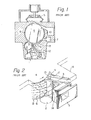
- FIG. 1 A conventionally known open-end spinning frame will now be explained with reference to Fig. 1.
- a sliver introduced from a collector 1 is delivered to a combing roller 4 which rotates counterclockwise. While the sliver is delivered, it is held by the fiber feeding mechanism.
- the mechanism is constructed with a feed roller 2 which is also rotatable in a counterclockwise direction and a presser 3 which is urged towards the feed roller 2.
- the sliver is then fed into a-rotor 5 which rotates at a high speed and a spun yarn is formed while it is taken up from the rotor 5.
- the combing roller 4 rotates at a speed of several thousand revolutions per minute so that a metallic wire wound therearound effects the combing operation to the fed fibers, and as a result, short fibers, dust and impurities contained within the fed-fibers are scattered.
- Some of the short fibers and so on, which will hereinafter be referred to as "flies,” may be discharged into a dust removing chamber 7 or fed into the inside of the rotor 5.
- many flies are discharged around the combing roller 4, especially at the narrow return passage 8 and on the lateral surfaces of the combing roller 4, because of the centrifugal force acting upon the flies when they are in a relatively large space adjacent to the fiber feeding mechanism.
- the discharged fibers may be accumulated on the combing roller 4.
- a vacuum is created because of the rotation of the rctor 5, and the vacuum facilitates the flow of the air thereinto.
- a flow-in air current A which flows into both a combing region 9 and a transferring region 10, is created by means of the air flowing into the rotor together with an air flow caused by the rotation of the combing roller 4. Accordingly, part of the flies are conveyed to the combing region 9 and the transferring region 10 by means of the flow-in air current A, but they are not accumulated on the fiber feeding mechanism.
- the inventors of the present invention focused on the flow-in air current A which is created in a portion of the fiber feeding mechanism.
- a specially designed construction is utilized so that a large amount of flowing air current, which is similar to the flow-in air current A, is created in a wide region and so that the movement of the flies is increased.
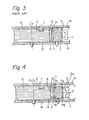
- the flow-in air current A mainly flows through a gap between the presser 3 and a casing 12. Consequently, the flowing region and the amount of air are very limited because the flanged surfaces 13 of the combing roller 4 are positioned at substantially the same heights as the upper and lower surfaces of the feed roller 2 and the presser 3 (see F ig. 3) so that the gaps between the feed roller 2, the presser 3 and the upper and lower flat side plates 14 are very small, and as a result, the air flow which passes by the feed roller 2 and the presser 3 into the combing region 9 does not occur easily.
- the feeding mechanism is provided with a passage for flowing air current which prevents the accumulation of fibers or flies around the fiber feeding mechanism at the widthwise side region thereof.
- the widths of the feed roller 2 and the presser 3 are shortened so that both the upper and lower surfaces of both the feed roller 2 and the presser 3 are positioned within the flanged surfaces of the combing roller 4, and as a result, large gaps are formed between them and the upper and lower flat side plates 14.
- the air current flowing into the combing region 9 comprises a flow-in air current A which is similar to that in a conventional apparatus, a flow-in air current B which passes by the presser 3 only, a flow-in air current C which passes by both the feed roller 2 and the presser 3, and a flow-in air current D which passes by the feed roller 2 only.
- the distance H 2 or H 2 ' between the flanged surface 13 and the upper or lower side surface of the presser 3 be equal to or larger than the distance H 1 or H 1 ' between the flanged surface 13 and the upper or lower side surface of the feed roller 2. This is because the flow resistance of the flow-in air currents, especailly the flow-in air currents B and C, at the side surfaces of the presser'3 is decreased.
- the front side 3a of the presser 3 may be chamfered a constant depth, as illustrated in Figs. 4, 5 and 6, thereby forming a widthwise step.
- the front side of the presser be obliquely chamfered.
- Fig. 7 illustrates another embodiment wherein only the front side surface 3a of the presser 3 is chamfered a constant depth so that the flow-in air currents A, B and C flow into the combing region 9.
- the amount of the flow-in air current C in this embodiemnt is not as large as that in the first embodiment.
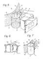
- Fig. 8 illustrates a further embodiment wherein the width of the feed roller 2 is made smaller than that of the combing roller 4.
- the flow-in air currents B and C are not easily produced because the pressor 3 is not chamfered.
- the flow-in air currents A and D are produced, and, the flow-in air current D especially facilitates the scattering movement of fibers or flies which have a tendency to accumulate at the narrow space between the presser 3 and the feed roller 2.
- a metallic wire 6 of the combing roller 4 is helically wound around the combing roller 4. If the metallic wire 6 is wound in a left-handed thread manner and the combing roller 4 is rotated in the direction of the arrow R, the fibers combed by the combing roller 4 are pressed upwards because of the axial force f caused by the rotation of the inclined metallic wire 6. As a result, the combed fibers have the tendency to pass by the upper portion of the combing roller 4, and there is also the tendency for the flies to gather at the upper portion. In this case, the gaps H 1 ' and H2 located at the lower portion of the fiber feeding mechanism are of no use for preventing the accumulation of fibers or flies.
- the presser 3 has a pair of projections 11, as illustrated by the broken line, at both ends of the front of the presser 3 which encircle the combed fibers so that the fibers gathered because of the axial force are stopped.
- the flies may become clogged in such projections. More specifically, as the combing roller rotates at high speed, flies, especially those released from the return passage 8, (see Fig. 1) are discharged to the fiber feeding mechanism, and they accumulate on the projections 11 (Fig. 3) extending towards the combing roller 4.
- the function of the presser 3 is less efficient, or a yarn breakage or degradation of the obtained yarn quality occurs when the clogged flies are again transferred into the spinning rotor 5.
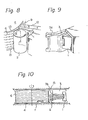
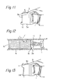
- only one projection 11 is formed at one end of the front 3b of the presser 3 and is located at a position opposite to the position to which the inclined metallic wire 6 is directed with respect to the rotating movement of the combing roller 4.
- a space 15 is formed between the front 3 b of the presser 3, the projection 11 and the combing roller 4, and through the space 15, the flow-in air current F (Fig. 11) flows so that the accumulation of flies is prevented.
- the front 3b of the presser 3 is formed so as to be perpendicular to the side 3a of the presser 3.
- the front 3b of the presser 3 may be slightly inclined forward as illustrated in Fics. 12 and 13.
- any one of the embodiments in Figs. 4 through 9 may be combined with that illustrated in Figs. 10 and 11 or Figs. 12 and 13.
- the device of the present invention is simple in construction. However, because of one or more air current flowing passages the accumulation of the fibers or flies can be remarkably prevented by one or more flow-in air currents through one or more of the passages. Because fibers or flies are not accumulated on the presser, the function of the presser is more efficient. The yarn breakage and the degradation of the spun yarn do not occur because the flies are not solidified and because the solidified flies do not enter into the spinning rotor. Also, according to the present invention, an additional advantage is that the flow-in air current facilitates the combing operation.
Landscapes
- Engineering & Computer Science (AREA)
- Mechanical Engineering (AREA)
- Textile Engineering (AREA)
- Preliminary Treatment Of Fibers (AREA)
- Spinning Or Twisting Of Yarns (AREA)
Applications Claiming Priority (4)
| Application Number | Priority Date | Filing Date | Title |
|---|---|---|---|
| JP141039/78U | 1978-10-13 | ||
| JP14103978U JPS5655262Y2 (de) | 1978-10-13 | 1978-10-13 | |
| JP141756/78U | 1978-10-16 | ||
| JP1978141756U JPS5720612Y2 (de) | 1978-10-16 | 1978-10-16 |
Publications (2)
| Publication Number | Publication Date |
|---|---|
| EP0010258A1 true EP0010258A1 (de) | 1980-04-30 |
| EP0010258B1 EP0010258B1 (de) | 1986-01-15 |
Family
ID=26473373
Family Applications (1)
| Application Number | Title | Priority Date | Filing Date |
|---|---|---|---|
| EP79103890A Expired EP0010258B1 (de) | 1978-10-13 | 1979-10-10 | Vorrichtung zur Vermeidung der Ansammlung von Fasern in einer Offenend-Spinnmaschine |
Country Status (3)
| Country | Link |
|---|---|
| US (1) | US4254612A (de) |
| EP (1) | EP0010258B1 (de) |
| DE (1) | DE2967566D1 (de) |
Cited By (2)
| Publication number | Priority date | Publication date | Assignee | Title |
|---|---|---|---|---|
| DE3604919A1 (de) * | 1985-01-22 | 1987-08-27 | Vyzk Ustav Bavlnarsky | Faseraufloesevorrichtung fuer offen-end-rotorspinnmaschinen |
| DE3709322A1 (de) * | 1987-03-21 | 1988-09-29 | Schlafhorst & Co W | Zufuehr- und aufloeseeinrichtung einer offen-end-spinnvorrichtung |
Families Citing this family (3)
| Publication number | Priority date | Publication date | Assignee | Title |
|---|---|---|---|---|
| CS264430B1 (en) * | 1987-06-15 | 1989-08-14 | Safar Vaclav | Device for fibres opening for spinning unit of spinning machine |
| DE19504607A1 (de) * | 1995-02-11 | 1996-08-14 | Schlafhorst & Co W | Faserbandzuführvorrichtung für OE-Spinnmaschinen |
| CZ298791B6 (cs) * | 2000-03-29 | 2008-01-30 | Rieter Cz A. S. | Podávací stolecek pramene vláken podávacího ústrojí pramene vláken sprádací jednotky sprádacího stroje |
Citations (5)
| Publication number | Priority date | Publication date | Assignee | Title |
|---|---|---|---|---|
| DE1915556A1 (de) * | 1968-04-16 | 1969-10-30 | Vyzk Ustav Bavlnarsky | Vorrichtung fuer den Eintritt eines Stapelfasergebildes,z.B. eines Faserbandes,in das Auflockerungsorgan einer Vorrichtung zum kontinuierlichen spindellosen Feinspinnen von Textilfasern |
| FR2015299A1 (de) * | 1968-08-08 | 1970-04-24 | Toyoda Automatic Loom Works | |
| FR2282491A1 (fr) * | 1974-08-22 | 1976-03-19 | Stahlecker Fritz | Dispositif de nettoyage d'une matiere fibreuse, pour une machine a filer a bout ouvert |
| DE2641897A1 (de) * | 1975-10-03 | 1977-04-14 | Vyzk Ustav Bavlnarsky | Verfahren zum aufloesen von stapelfasern aus dem faserband und vorrichtung zum durchfuehren des verfahrens |
| DE2718146A1 (de) * | 1976-04-26 | 1977-10-27 | Toyoda Automatic Loom Works | Offen-end-spinnvorrichtung |
Family Cites Families (5)
| Publication number | Priority date | Publication date | Assignee | Title |
|---|---|---|---|---|
| US3626681A (en) * | 1968-08-08 | 1971-12-14 | Toyoda Automatic Loom Works | Ringless spinning machine |
| CH510751A (de) * | 1968-11-21 | 1971-07-31 | Vyzk Ustav Bavlnarsky | Auskämmvorrichtung mit einer Kämmwalze an einer Spinnstelle einer spindellosen Feinspinnmaschine |
| GB1368886A (en) * | 1972-03-13 | 1974-10-02 | Platt International Ltd | Open-end textile spinning machines |
| CS163568B1 (de) * | 1973-03-08 | 1975-09-15 | ||
| JPS5045437U (de) * | 1973-09-03 | 1975-05-07 |
-
1979
- 1979-10-09 US US06/082,723 patent/US4254612A/en not_active Expired - Lifetime
- 1979-10-10 DE DE7979103890T patent/DE2967566D1/de not_active Expired
- 1979-10-10 EP EP79103890A patent/EP0010258B1/de not_active Expired
Patent Citations (5)
| Publication number | Priority date | Publication date | Assignee | Title |
|---|---|---|---|---|
| DE1915556A1 (de) * | 1968-04-16 | 1969-10-30 | Vyzk Ustav Bavlnarsky | Vorrichtung fuer den Eintritt eines Stapelfasergebildes,z.B. eines Faserbandes,in das Auflockerungsorgan einer Vorrichtung zum kontinuierlichen spindellosen Feinspinnen von Textilfasern |
| FR2015299A1 (de) * | 1968-08-08 | 1970-04-24 | Toyoda Automatic Loom Works | |
| FR2282491A1 (fr) * | 1974-08-22 | 1976-03-19 | Stahlecker Fritz | Dispositif de nettoyage d'une matiere fibreuse, pour une machine a filer a bout ouvert |
| DE2641897A1 (de) * | 1975-10-03 | 1977-04-14 | Vyzk Ustav Bavlnarsky | Verfahren zum aufloesen von stapelfasern aus dem faserband und vorrichtung zum durchfuehren des verfahrens |
| DE2718146A1 (de) * | 1976-04-26 | 1977-10-27 | Toyoda Automatic Loom Works | Offen-end-spinnvorrichtung |
Cited By (4)
| Publication number | Priority date | Publication date | Assignee | Title |
|---|---|---|---|---|
| DE3604919A1 (de) * | 1985-01-22 | 1987-08-27 | Vyzk Ustav Bavlnarsky | Faseraufloesevorrichtung fuer offen-end-rotorspinnmaschinen |
| US4815269A (en) * | 1987-03-20 | 1989-03-28 | W. Schlafhorst & Co. | Silver opening and feeding device for an open-end spinning device |
| DE3709322A1 (de) * | 1987-03-21 | 1988-09-29 | Schlafhorst & Co W | Zufuehr- und aufloeseeinrichtung einer offen-end-spinnvorrichtung |
| DE3709322C2 (de) * | 1987-03-21 | 1999-10-14 | Schlafhorst & Co W | Zuführ- und Auflöseeinrichtung einer Offenend-Spinnvorrichtung |
Also Published As
| Publication number | Publication date |
|---|---|
| US4254612A (en) | 1981-03-10 |
| DE2967566D1 (en) | 1986-02-27 |
| EP0010258B1 (de) | 1986-01-15 |
Similar Documents
| Publication | Publication Date | Title |
|---|---|---|
| US3834145A (en) | Open-end spinning of textile yarns | |
| US3626681A (en) | Ringless spinning machine | |
| US3785138A (en) | Spinning unit for open end spinning machine | |
| US4392276A (en) | Fiber separator for feeding a freed-fiber spinning unit | |
| CZ297892B6 (cs) | Vývodka príze | |
| US4249370A (en) | Method of and apparatus for removing dirt particles from staple fibers and for straightening said fibers in an open-end spinning process | |
| US4254612A (en) | Device for preventing the accumulation of fibers in an open-end spinning frame | |
| US4507827A (en) | Cleaning machine for fiber material | |
| US4274178A (en) | Device for stripping a fibrous web from a doffer in a carding machine | |
| US4486922A (en) | Apparatus for separating impurities from fiber material | |
| US4497089A (en) | Fiber drafting arrangement | |
| US3696605A (en) | Ringless spinning machine | |
| US5065572A (en) | Fiber supply arrangement for open-end rotor spinning | |
| US4459801A (en) | Feeding and opening device for open-end spinning units with a separation opening for impurities | |
| EP0071453A2 (de) | Offenend-Spinnmaschine | |
| US4815269A (en) | Silver opening and feeding device for an open-end spinning device | |
| JP3295135B2 (ja) | ロータ式オープンエンド精紡装置 | |
| US3999250A (en) | Method of fiber distribution and ribbon forming | |
| US4718227A (en) | Open-end spinning process and device for its implementation | |
| US5088266A (en) | Sliver feeding and opening device of an open-end spinning machine | |
| US4825637A (en) | Fiber opening device in a spinning unit of an open-end spinning machine | |
| US5373690A (en) | Process and device for pneumatic conveying of fibers to the fiber collection surface of an open-end spinning element | |
| US4308717A (en) | Dust removing mechanism in open-end spinning frame | |
| EP0035191A1 (de) | Gesponnene Offenend-Effektgarne | |
| US5749216A (en) | Open end spinning apparatus |
Legal Events
| Date | Code | Title | Description |
|---|---|---|---|
| PUAI | Public reference made under article 153(3) epc to a published international application that has entered the european phase |
Free format text: ORIGINAL CODE: 0009012 |
|
| 17P | Request for examination filed | ||
| AK | Designated contracting states |
Designated state(s): CH DE FR GB |
|
| GRAA | (expected) grant |
Free format text: ORIGINAL CODE: 0009210 |
|
| AK | Designated contracting states |
Designated state(s): CH DE FR GB |
|
| ET | Fr: translation filed | ||
| REF | Corresponds to: |
Ref document number: 2967566 Country of ref document: DE Date of ref document: 19860227 |
|
| PLBE | No opposition filed within time limit |
Free format text: ORIGINAL CODE: 0009261 |
|
| STAA | Information on the status of an ep patent application or granted ep patent |
Free format text: STATUS: NO OPPOSITION FILED WITHIN TIME LIMIT |
|
| 26N | No opposition filed | ||
| PG25 | Lapsed in a contracting state [announced via postgrant information from national office to epo] |
Ref country code: CH Effective date: 19871031 |
|
| GBPC | Gb: european patent ceased through non-payment of renewal fee | ||
| PG25 | Lapsed in a contracting state [announced via postgrant information from national office to epo] |
Ref country code: FR Free format text: LAPSE BECAUSE OF NON-PAYMENT OF DUE FEES Effective date: 19880630 |
|
| REG | Reference to a national code |
Ref country code: CH Ref legal event code: PL |
|
| PG25 | Lapsed in a contracting state [announced via postgrant information from national office to epo] |
Ref country code: DE Effective date: 19880701 |
|
| REG | Reference to a national code |
Ref country code: FR Ref legal event code: ST |
|
| PG25 | Lapsed in a contracting state [announced via postgrant information from national office to epo] |
Ref country code: GB Effective date: 19881118 |