EP0007692A2 - Appareil et méthode pour le remplissage d'un sac à valve avec du matériau pulvérulent - Google Patents
Appareil et méthode pour le remplissage d'un sac à valve avec du matériau pulvérulent Download PDFInfo
- Publication number
- EP0007692A2 EP0007692A2 EP79301063A EP79301063A EP0007692A2 EP 0007692 A2 EP0007692 A2 EP 0007692A2 EP 79301063 A EP79301063 A EP 79301063A EP 79301063 A EP79301063 A EP 79301063A EP 0007692 A2 EP0007692 A2 EP 0007692A2
- Authority
- EP
- European Patent Office
- Prior art keywords
- valve
- nozzle
- filling
- air
- water
- Prior art date
- Legal status (The legal status is an assumption and is not a legal conclusion. Google has not performed a legal analysis and makes no representation as to the accuracy of the status listed.)
- Withdrawn
Links
Images
Classifications
-
- B—PERFORMING OPERATIONS; TRANSPORTING
- B65—CONVEYING; PACKING; STORING; HANDLING THIN OR FILAMENTARY MATERIAL
- B65B—MACHINES, APPARATUS OR DEVICES FOR, OR METHODS OF, PACKAGING ARTICLES OR MATERIALS; UNPACKING
- B65B1/00—Packaging fluent solid material, e.g. powders, granular or loose fibrous material, loose masses of small articles, in individual containers or receptacles, e.g. bags, sacks, boxes, cartons, cans, or jars
- B65B1/04—Methods of, or means for, filling the material into the containers or receptacles
- B65B1/18—Methods of, or means for, filling the material into the containers or receptacles for filling valve-bags
-
- B—PERFORMING OPERATIONS; TRANSPORTING
- B65—CONVEYING; PACKING; STORING; HANDLING THIN OR FILAMENTARY MATERIAL
- B65B—MACHINES, APPARATUS OR DEVICES FOR, OR METHODS OF, PACKAGING ARTICLES OR MATERIALS; UNPACKING
- B65B7/00—Closing containers or receptacles after filling
- B65B7/02—Closing containers or receptacles deformed by, or taking-up shape, of, contents, e.g. bags, sacks
- B65B7/025—Closing valve bags
Definitions
- the present invention relates to an apparatus and method for filling a valve bag with particulate material.
- a novel filling spout is employed for filling valve bags with particulate materials while insuring that a proper valve seal is obtained so that leakage of material through the valve is virtually eliminated.
- Particulate materials are commonly packaged in bags that are made from multiple layers of paper and have a "valve" in one upper corner.
- the valve provides an opening through which the material is dispensed during the bag filling operation.
- the valve bag is typically filled by inserting a spout or nozzle into the valve and causing material to flow through the nozzle into the bag.
- a spout or nozzle into the valve and causing material to flow through the nozzle into the bag.
- the flow of material is halted and the nozzle is withdrawn from the valve usually by moving the bag away from the nozzle.
- the valve is sealed to prevent egress of the material from the bag during shipping and handling.
- United States Patent No. 3,083,780 also relates to the filling of bags with tuck-in valves or glued interior valves, and steps are also taken to remove material from the valve before removal of the bag from the nozzle, but this material removal is effected by blowing the material in the nozzle into the bag prior to disengagement.
- United States Patent No. 4,066,108 shows another valve arrangement which is of the exterior or extended variety but is sealed by heat rather than tucking or folding. Prevention of contamination of the valve interior by the dispensed material is attempted by forming a relatively tight seal around the nozzle when it is inserted in the valve and further by inclining the bag so that the valve opening points upwardly upon removal of the nozzle and prior to sealing.
- a filling operation performed with the bag in one position may be followed by a-sealing operation with the bag moved to another position as is described in United States Patents Nos. 4,066,108 or 3,083,780.
- a-sealing operation with the bag moved to another position as is described in United States Patents Nos. 4,066,108 or 3,083,780.
- Such a system for filling and sealing bags in addition to requiring two operations and the attendant equipment, may be subject to poor sealing since material may enter the valve from the end of the filling nozzle when the bag is moved to the sealing position and the nozzle emerges from the valve. This may be a particular problem in a glued sleeve sealing system such as that of United States Patent No. 3,083,780 in which the bag is moved through a considerable distance and then the glue on the interior valve is sprayed with water without any prior cleaning of the valve surface.
- apparatus for filling with particulate material a valve bag having an elongated valve lined with a water activated sealing means, including water supply means for supplying water to a location adjacent the surface of the water activated sealing means, characterised in that the water supply means includes water spray supply means having at least one spray nozzle for delivering an air/water spray to a location adjacent the valve lining to activate the sealing means of the valve.
- the water spray supply means includes an air supply duct for continuously supplying air under pressure to the spray nozzle, and a water supply for selectively-introducing a measured amount of water into the air to produce the spray from the spray nozzle.
- the water spray supply means includes conduit means extending along an elongated filling nozzle for insertion into the valve, which conduit means leads to the spray nozzle which is positioned to dispense the air/water spray within a cavity on the outside of the filling nozzle at said location adjacent the valve lining.
- an air supply conduit means extending along the filling nozzle for supplying air under pressure to the cavity - to maintain the interior surface of the filling valve adjacent the cavity free from contamination by particulate material being delivered by the filling nozzle.
- an air vent conduit extending-along the filling nozzle from a vent opening spaced from the end of the filling nozzle, to provide an exhaust path for air within the bag during the filling operation.
- suction conduit connected, to the filling nozzle and communicating with the passage for particulate material through the filling nozzle.
- the invention also provides a method for filling with particulate material a valve bag having an elongated valve lined with a water activated sealing means, comprising inserting the elongated filling nozzle into the valve, dispensing a flowable particulate material through the nozzle into the valve bag until the valve bag contains a predetermined amount of the material, and venting air from the interior of the valve bag while dispensing the flowable particulate material into the valve bag, characterised by producing a water spray by mixing a predetermined amount of water with air, delivering the water spray through a conduit along the nozzle to a water spray passage at a location on an outside surface of the nozzle after the valve bag contains the predetermined amount of material in order to discharge the water spray over a surface of the water activated sealing means and thereby activate the sealing means, and removing the nozzle from the valve in order to seal the valve.
- Suction may be applied momentarily to the interior of the filling nozzle adjacent an exterior portion thereof after partially removing the nozzle from the valve in order to move material in the nozzle away from the discharge end of the nozzle.
- the water spray may be delivered to the interior of a cavity in the outside surface of the filling nozzle.
- Air may be continuously discharged into said cavity while the material is being dispersed into the interior of the valve bag.
- the method may include discharging air into said cavity while dispensing particulate material into the. interior of the valve bag, and introducing said predetermined amount of water into said discharged air prior to its discharge into said cavity to produce said water spray after the valve bag contains said predetermined amount of material.
- valve bag In another way of operating the valve bag is filled and the filling nozzle is removed.
- An elongated sealing member is then inserted into the valve at least to a position adjacent the sealing means and air under pressure is introduced through a first conduit to free the sealing means from contamination by particulate material.
- the water spray is then introduced at the position adjacent the sealing means through a second conduit in order to activate the sealing means.
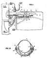
- the present invention may be used with a suitable conventional filling machine generally indicated at 10 which typically induces a suitable conventional dust collector 12.
- Particulate material is supplied through a filling nozzle 14 on the filling machine 10 to the interior 16 of a valve bag 18.
- the filling nozzle is inserted through a filling valve 20 at the upper side portion of the bag.
- the supply of material from the filling machine 10 may be either through forced flow, i.e., by introducing the fluid through the nozzle under pressure, or by what is referred to as fluid flow, i.e., where the material flows by the force of gravity but is assisted by air jets in the vicinity of the nozzle.
- the valve bag rests on a platform (not shown) which is movable so as to move the bag and cause the nozzle 14 to be inserted a predetermined distance into the bag (i.e. so that the end of the nozzle extends beyond the end of the valve as illustrated).
- the valve 20 is provided with a water activated sealing means on an interior surface thereof so that when this sealing means is activated by the application of water thereto, the opposing surfaces of the interior of the filling valve will adhere to each other when the nozzle is removed.
- This water activated sealing means 22 may comprise a dry glue as shown in United States Patent No. 3,083,780 but preferably comprises a water soluble plastic liner known commercially as a "Solu-Seal" (Trade Mark) liner.
- Solu-Seal Trade Mark
- the nozzle 14 of the preferred embodiment of the invention includes an elongated member 24 that extends between the particulate material source in the filling machine 10 and the interior of the valve bag 18 beyond the interior extremity of the filling valve 20 when the valve bag 18 is in a filling position as illustrated in Figure 1.
- the elongated member 24 has a material passage 26 extending entirely therethrough for the introduction of the particulate material into the interior of the bag from the filling machine 10.
- the nozzle 14 also has a conventional vent conduit 28 disposed along the lower periphery thereof.
- the vent conduit 28 has an open end adjacent the discharge end of the nozzle 14 and extends between the interior of the valve bag 18 and the exterior thereof adjacent the dust collector 12.
- the vent conduit 28 allows air to freely escape from the interior of the valve bag during a filling operation.
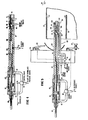
- the elongated member 24 is a hollow tube with a flange 25 for connection to the filling machine frame, and the interior of the tube forms the material supply passage.
- Two sets of first and second conduits 30, 30', and 32, 32' extend along the member 24 on opposite sides thereof and communicate between the exterior of the valve bag and a cavity 34.
- the conduits are connected to the member 24 by welding or by other suitable techniques.
- the cavity 34 is formed along the peripheral surface of the nozzle 14 at a location adjacent the water activated sealing means 22 on the interior surface of the valve 20.
- the conduits 30, 30' lead from a water spray source (described hereinafter in detail) outside the valve bag to spray nozzles 36, 36' within the cavity 34 on opposite sides thereof.
- the conduit 32 extends between a source of drying air outside the valve bag to conduits 38 and 40 that curve radially around the member 24 through an angle of about 180° and form the forward and rearward edges of the cavity 34.
- the conduits 38 and 40 have a number of holes spaced therealong to form air jets to direct air into the cavity as will be described hereinafter in greater detail.
- conduits disposed along the elongated member is intended to encompass conduits that are within the member or formed as part of the member or other like arrangements that provide the disclosed functions of these conduits and the cavity.
- a suction conduit 42 connected to a suction source may communicate with the material supply passage 26 through a valve 44 controlled by an air piston 46 as is shown more clearly in Figure 2.
- the valve 44 is preferably controlled to apply suction to the passage 26 for a very short period of time during removal of the nozzle from the filling valve to move material in the nozzle away from its discharge end as will be subsequently described.
- particulate material is forced by gravity fluid flow or pressure through the passage 26 in the nozzle 14 into the interior of the valve bag 18.
- air within the bag 18 vents through the conduit 28 to the vicinity of the dust collector 12 and any dust in the air is collected.
- the valve bag is full as is conventionally determined by weight or other suitable measure, the flow of particulate material through the nozzle 4 is halted, usually by a suitable pinch valve (not shown).
- air is continuously supplied from a suitable drying air source through the conduits 32 and 32' to the respective conduits 38 and 40, which in turn direct the air into the cavity 34 from the front and rear edges thereof.
- the cavity 34 extends around the periphery of the nozzle 14 throughout approximately 180° and the conduits 38 and 40 provide air jets along the entire extent of the forward and rearward edges of the cavity as will be seen hereinafter.
- Air is preferably continuously supplied to the conduits 38 and 40 by way of the conduit 32 during the entire filling operation so that the cavity 34 is at a positive air pressure with respect to the interior pressure of the bag 16 during the entire filling operation.
- the air supplied to the cavity 34 keeps the valve 20 dry in the vicinity of the cavity in the event that water is present from a previous filling operation. Moreover, the air supplied to the cavity leaks from the cavity across its peripheral edges causing air flow away from the cavity between the filling valve and the nozzle at least in the vicinity of the cavity. Some positive air flow will thus be created along the surface of the filling valve toward the interior of the bag, thus preventing particulate material from entering the valve and contaminating the valve in the vicinity of the cavity 34. Also, this air flow apparently creates a venturi effect that holds the valve surface against the edges of the cavity 34, creating a seal around the cavity.
- a valve may be provided in the drying air line to cut off drying air to the conduits 32, 32' when the removal operation begins.
- the air cylinder 46 is actuated to connect the interior of the filling nozzle (i.e. the material fill passage) to the suction source through conduit 42 for a period of time sufficient to move the particulate material in the nozzle back away from the discharge end thereof.
- this time period will vary depending on the material being dispensed, the value of the suction applied, the size of the suction conduit, and similar considerations. It is contemplated, however, that this time period will be set at less than one second and perhaps as low as 0.1 second.
- particulate material is moved away from the end of the nozzle without sucking material out of the bag.
- the material therefore will not drop from the discharge end of the nozzle onto the water activated surface of the sealing means as the nozzle is removed from the filling valve.
- the vent 28 may accumulate a quantity of material in the end thereof that extends into the interior of the valve bag adjacent the discharge end of the nozzle. Accordingly, a valve in the vent conduit 28 may be closed and a second valve opened when the air cylinder is actuated in order to mome - ntarily connect the suction source to the vent conduit 28 and similarly move any material therein away from the end of the conduit 28 that is within the valve bag (as shown in phantom in Figure 2).
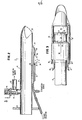
- Figures2, 2A and 3 illustrate the preferred embodiment of the nozzle in greater detail.
- the nozzle 14 is generally of hollow, tubular construction and is slightly tapered with a smooth, rounded discharge and for easy entry into the filling valve.
- the conduits for the air and water mixture and the drying air run along the exterior surface of the nozzle and are covered with suitable baffles or deflectors 50 ( Figure 3) in order to form a smooth somewhat oval surface that inserts easily into the filling nozzle of the valve bag and generally conforms to its shape.
- Suitable rods 52 may additionally be provided at the front end of the nozzle across both the material passage opening and the vent opening in order to prevent these openings from snagging on the filling valve as the nozzle is inserted.
- the cavity 34 is formed by the conduits 38 and 40 as they wrap around the periphery of the nozzle.
- the conduit 38 is supplied with drying air by the conduit 32 running along one side of the nozzle and the conduit 40 is supplied with drying air by the conduit 32' running along the other side of the nozzle.
- the water spray nozzle _36 is supplied with an air and water mixture by the conduit 30 and a water spray nozzle 36' on the other side of the nozzle is.supplied by a conduit 30' running along the other side of the nozzle.
- the water spray nozzles are formed in any suitable conventional manner, as by capping the conduits 30, 30' where they end in the vicinity of the centre line of the cavity 34 and providing an orifice of about 1.02 mm that directs water downwardly into the cavity toward the water activated sealing means on the interior of the filling valve. It can also be seen that the drying air jets may be formed in the conduits 38 and 40 by similarly drilling holes therethrough at locations that direct drying air into the cavity 34, preferably at a slightly upward angle.
- vent 28 may be of any suitable shape and is preferably of sufficient size to permit air to freely vent from the interior of the bag as it is being filled.
- an elongated vent as illustrated in Figure 2A may be provided.
- Each of the conduits 30, 30' is connected to its own water spray source in the illustrated embodiment.
- the water spray sources are preferably constructed so that air normally flows through the conduits 30, 30' at all times (or is at least controllable independently of water flow) and a measured amount of water is introduced into this air stream at the time it is desired to activate the water activated sealing means.
- a preferred form of a water spray source that provides independently controllable air flow with controlled, intermittent water spray is illustrated in Figure 4.
- the water spray source includes a water cylinder 60 that is connected to a water source at 62.
- a piston 64 controlled between an extended position (indicated in phantom at 66) and the illustrated retracted position by an air piston 68.
- a ball valve 70 At the other end of the cylinder 60 is a ball valve 70 that is biased by a spring 72 against a sealing ring 74 so that the interior chamber 61 of the cylinder 60 is normally sealed with sufficient biasing force that there is no leakage of water from the chamber 61 under the action of normal water pressure of the water source.
- the cylinder 60 is provided with coaxial extension 76 with an interior bore 77 that extends beyond the valve 70 and includes an outlet port 78.
- a source of air pressure is connected to communicate with and provide air to the bore 77 at 80 as illustrated. Air introduced by a duct 80 flows through the bore 77 and exits at the outlet port 78, which port is connected to one of the water spray conduits 30, 30' ( Figure 2).
- Air for control of the air cylinder and piston 68 is introduced at two ports 82 and 84.
- a suitable conventional control valve 86 receives air under pressure from a suitable source as illustrated and selectively applies the compressed air to one or the other of the ports 82 and 84 as conventionally directed by a signal supplied electrically or hydraulically at control line 88. It will be appreciated that introduction of air through the port 82 will cause the piston 64 to be moved to its extended position, while the directing of air through port 84 will cause the piston 64 to be retracted.
- an adjustable stop 90 is provided with a threaded barrel 92 to ad- justably control the extent of retraction of the piston 64 and thus control the size of the chamber 61 and the amount of water it will accept from the water source.
- air is supplied at 80 and flows through the bore 77 to the outlet port 78 and through one of the conduits 30, 30'. Air may be thus supplied continuously during a filling operation (including during the time in which the nozzle is being retracted and a new bag is being placed in the filling position) or a valve (not shown) in the air line 80 may be selectively operated to shut off air flow during selected periods (e.g. as the nozzle is being removed).
- Water is supplied to the chamber 61 of the cylinder 60 so that the chamber is full prior to initiation of a water spray to activate the sealing means in the filling valve.
- water may be continuously supplied to the chamber 61 or a valve (not shown) in the line 62 may be closed immediately prior to and during the water spray period (i.e. when the piston 64 is extended) to prevent the egress of water through line 62 under the action of the piston 64.
- the stop 90 is set at a desired position in order to calibrate the effective size of the chamber 61. Accordingly, when the air piston 68 is actuated to extend the piston 64, a measured amount of water is forced through the ball valve 70 into the air stream flowing through the bore 77.
- the bag may be filled by using the nozzle of Figures 1-3 without performing the sealing steps or by using any other suitable filling technique.
- the filling nozzle may be removed from the filling valve and a sealing nozzle such as that illustrated in Figure 5 may be inserted into the valve to clean and seal it.
- the bag when the. valve bag 18 is filled, the bag may be moved or merely repositioned (e.g. by tilting) to remove the filling nozzle from the valve 20.
- a sealing nozzle 100 may then be inserted a predetermined distance into the valve 20.
- the sealing nozzle is then operated to clean. and activate the sealing means 22 on the interior of the filling valve.
- the sealing nozzle 100 includes an elongated member 102 that is insertable into the filling valve 20 without engaging at least that portion of the sealing means 22 that is to water activated and, in the preferred embodiment, without engaging any of the interior portion of the filling nozzle.
- the member 102 is constructed and operates identically to the water spray piston device described in connection with Figure 4 except that the output end 104 of the device is not connected to an output tube or conduit as in the device of Figure 4 but, rather, is capped and provided with a deflector 106 and output ports 108 as illustrated. Accordingly, like numerical designations have been used in Figure 5 to indicate elements previously discussed in connection with Figure 4.
- the deflector 106 is cylindrical and is provided with a set screw 109 to attach it in a desired position relative to two or more output ports 108 that direct air and water spray against an inwardly angled, frustro-conical surface 110 as illustrated.
- the surface 110 deflects the air (during initial valve cleaning) and water spray (during activation of the sealing means) against the water activated sealing means on the interior of the filling valve.
- a valve 112 in the air supply line to the air inlet 80 is mechanically coupled to a handle 114 on a housing or other suitable frame 116 suspended at a convenient location near the filling machine.
- the handle 114 when depressed by the operator, opens the valve 112 and allows air to flow to the interior bore 77 and through the outlet ports 108 where the air is deflected by the surface 110 against the interior of the valve in a direction outwardly from the interior of the bag. This air flow results in cleaning of the valve surface 22 and is accomplished as the operator is inserting the member 102 into the valve.
- the valve 86 is mechanically coupled at 118 to an adjustable stop 120 located on the housing 116 at a position where it will contact the side of the filled bag.
- the stop is set so that it contacts the bag and opens the valve 86 automatically when the member 102 has been inserted into the valve 20 to a point at which the deflector 106 is in the vicinity of the sealing means and will deflect water emerging from the ports 108 onto the sealing means.
- the stop 120 contacts the bag, its mechanical coupling causes the valve 86 to apply air to the inlet port 82 which, in turn, causes the piston 64 to be extended. As was previously mentioned, this causes a measured amount of water to be forced through the ball valve 70 into the air stream flowing through the bore 77, thus spraying the filling valve interior to activate the sealing means.
- the sealing device can then be withdrawn from the valve and the valve can be sealed by application of pressure to the top of the bag over the valve.
Landscapes
- Engineering & Computer Science (AREA)
- Mechanical Engineering (AREA)
- Basic Packing Technique (AREA)
Applications Claiming Priority (2)
| Application Number | Priority Date | Filing Date | Title |
|---|---|---|---|
| US05/913,541 US4219054A (en) | 1978-06-07 | 1978-06-07 | Method and apparatus for filling valve bags |
| US913541 | 1978-06-07 |
Publications (2)
| Publication Number | Publication Date |
|---|---|
| EP0007692A2 true EP0007692A2 (fr) | 1980-02-06 |
| EP0007692A3 EP0007692A3 (fr) | 1980-06-11 |
Family
ID=25433377
Family Applications (1)
| Application Number | Title | Priority Date | Filing Date |
|---|---|---|---|
| EP79301063A Withdrawn EP0007692A3 (fr) | 1978-06-07 | 1979-06-05 | Appareil et méthode pour le remplissage d'un sac à valve avec du matériau pulvérulent |
Country Status (2)
| Country | Link |
|---|---|
| US (1) | US4219054A (fr) |
| EP (1) | EP0007692A3 (fr) |
Cited By (6)
| Publication number | Priority date | Publication date | Assignee | Title |
|---|---|---|---|---|
| EP0107924A2 (fr) * | 1982-09-30 | 1984-05-09 | Champion International Corporation | Appareil et procédé pour le remplissage d'un sac à valve |
| EP0107926A2 (fr) * | 1982-09-28 | 1984-05-09 | Champion International Corporation | Système de commande électro-pneumatique pour un appareil de remplissage de sacs à valve |
| DE3442185A1 (de) * | 1984-11-17 | 1986-05-28 | Haver & Boecker, 4740 Oelde | Verfahren und vorrichtung zum schliessen des ventils eines mittels einer mit ein oder mehreren fuellstutzen ausgeruesteten fuellmaschine gefuellten sackes |
| DE3905526A1 (de) * | 1989-02-23 | 1990-08-30 | Chronos Richardson Gmbh | Entlueftungssonde |
| CN107792407A (zh) * | 2017-09-27 | 2018-03-13 | 铜陵海源超微粉体有限公司 | 一种高效超微粉碎物料灌包装置 |
| CN115570781A (zh) * | 2022-10-04 | 2023-01-06 | 罗浮阀门集团有限公司 | 一种安全阀的阀体衬里工艺 |
Families Citing this family (41)
| Publication number | Priority date | Publication date | Assignee | Title |
|---|---|---|---|---|
| JPS58149259A (ja) * | 1982-01-30 | 1983-09-05 | 中島 重夫 | 弁付き包装袋 |
| US4471820A (en) * | 1982-09-24 | 1984-09-18 | Lepisto J George | Valve bag filling nozzle |
| US4574851A (en) * | 1982-09-28 | 1986-03-11 | Champion International Corporation | Apparatus for filling a valve bag |
| US4576210A (en) * | 1982-09-28 | 1986-03-18 | Champion International Corporation | Duck bill filler nozzle |
| US4567922A (en) * | 1982-09-28 | 1986-02-04 | Champion International Corporation | Method of filling valve bags |
| SE454770B (sv) * | 1984-07-31 | 1988-05-30 | Tetra Dev Co | Ventilarrangemang vid forpackningsmaskin |
| US4648432A (en) * | 1985-07-12 | 1987-03-10 | Emmanuel Mechalas | Vacuum apparatus for filling bags with particulate material including dust collector and recycling of collected material |
| US4688370A (en) * | 1986-02-18 | 1987-08-25 | The Dow Chemical Company | Method and machine for filing and sealing a multiwall valve bag |
| GB8817708D0 (en) * | 1988-07-25 | 1988-09-01 | Portals Eng Ltd | Improvements in filling machines |
| US5531252A (en) * | 1989-09-15 | 1996-07-02 | B.A.G. Corporation | Vacuum fill system |
| US5244019A (en) * | 1989-09-15 | 1993-09-14 | Better Agricultural Goals Corp. | Vacuum fill system |
| US5447183A (en) * | 1989-09-15 | 1995-09-05 | B.A.G. Corp. | Vacuum fill system |
| US5234037A (en) * | 1989-09-15 | 1993-08-10 | B.A.G. Corporation | Vacuum fill system |
| US5279339A (en) * | 1989-09-15 | 1994-01-18 | B.A.G. Corporation | Full sack compressor |
| US5509451A (en) * | 1989-09-15 | 1996-04-23 | B.A.G. Corporation | Vacuum fill system |
| US5538053A (en) * | 1989-09-15 | 1996-07-23 | Better Agricultural Goals Corporation | Vacuum densifier with auger |
| DE4305527C2 (de) * | 1993-02-24 | 1995-09-14 | Haver & Boecker | Füllrohr, insbesondere für eine zum Füllen von Ventilsäcken ausgelegte Füllmaschine |
| DE29622064U1 (de) * | 1996-12-19 | 1997-03-06 | Haver & Boecker, 59302 Oelde | Füllmaschine zum Absacken unterschiedlicher Produkte in Ventilsäcke |
| ES2217005T3 (es) | 1999-12-15 | 2004-11-01 | Kellogg Company | Recipiente transportable para mercancias a granel, y metodo para formar el recipiente. |
| AU2002210133A1 (en) | 2000-05-31 | 2001-12-11 | Fogg Filler Company | Separator assembly for filler device and associated method |
| US6338370B1 (en) | 2000-05-31 | 2002-01-15 | Fogg Filler Company | Fill valve assembly for filler device and associated method |
| CA2428882C (fr) * | 2000-11-20 | 2007-08-28 | Stone Container Corporation | Dispositif et procede de remplissage et de scellage de sacs a valve |
| US20040026292A1 (en) * | 2000-12-15 | 2004-02-12 | Ours David C. | Transportable container for bulk goods and method for forming the container |
| US20040163518A1 (en) * | 2001-04-26 | 2004-08-26 | Michael Resterhouse | Separator assembly for filler device and associated method |
| US6786248B2 (en) | 2001-10-11 | 2004-09-07 | Fogg Filler Company | Fill valve assembly for filler device |
| US6889482B2 (en) | 2002-10-10 | 2005-05-10 | Fogg Filler Company | Filler device sub-assembly |
| SE525952C2 (sv) * | 2003-10-02 | 2005-05-31 | Eco Lean Res & Dev As | Metod och anordning för gasfyllning och försegling av en för gasfyllning avsedd kanal i en förpackning av kollapsande slag, samt ett förpackningsämne innefattande en sådan kanal |
| US6892768B1 (en) * | 2003-12-10 | 2005-05-17 | Kellogg Company | Stretch wrap transportable container and method |
| US6945015B2 (en) * | 2003-12-10 | 2005-09-20 | Kellogg Company | Shrink wrap transportable container and method |
| EP1658948A3 (fr) * | 2004-11-22 | 2007-12-26 | N.V. Soudan Patrimonium And Consulting | Dispositif de fabrication de coussins en mousse |
| US7536840B2 (en) * | 2005-02-18 | 2009-05-26 | Kellogg Company | Stackable bulk transport container |
| US7243478B2 (en) * | 2005-04-04 | 2007-07-17 | Walker-Dawson Interests, Inc. | Vacuum system manifold and related methods |
| WO2009149316A1 (fr) | 2008-06-05 | 2009-12-10 | Kellogg Company | Base de transporteur unitaire et outil de mise en forme et machine à former à cadre de glissement pour former un contenant transportable |
| ES2449385T3 (es) | 2008-06-11 | 2014-03-19 | Kellogg Company | Procedimiento para llenar y formar un recipiente transportable para mercancias a granel |
| ES2821374T3 (es) * | 2008-09-03 | 2021-04-26 | Kellog Co | Sistema para producir un contenedor transportable para mercancías a granel |
| US8915270B2 (en) | 2009-10-05 | 2014-12-23 | Fogg Filler Company | Filler device having an enclosure sub-assembly |
| US9126705B2 (en) | 2010-12-01 | 2015-09-08 | Kellogg Company | Transportable container for bulk goods and method for forming the same |
| US10597277B2 (en) | 2011-07-08 | 2020-03-24 | Fogg Filler Company | Fill valve assembly for filler device and associated method of use |
| US20160009489A1 (en) * | 2014-07-10 | 2016-01-14 | Quick Sand Solutions, Llc | Proppant storage system and method |
| CN104326097A (zh) * | 2014-10-20 | 2015-02-04 | 锐派包装技术(上海)有限公司 | 一种用于阀口袋包装机的喂料伸缩嘴结构 |
| DE102018125212A1 (de) * | 2018-10-11 | 2020-04-16 | Haver & Boecker Ohg | Packanlagenkomponente mit einem Ventilsackfüllrohr zum Füllen von Ventilsäcken |
Citations (4)
| Publication number | Priority date | Publication date | Assignee | Title |
|---|---|---|---|---|
| GB405712A (en) * | 1931-08-15 | 1934-02-15 | Arno Andreas | Improvements in or relating to valve sacks or valve bags and to means for sealing them |
| US2060011A (en) * | 1931-03-30 | 1936-11-10 | Bagpak Inc | Bag filling machine |
| US2861604A (en) * | 1956-05-22 | 1958-11-25 | Volunteer Portland Cement Comp | Bag filling spout |
| FR2326342A1 (fr) * | 1975-10-03 | 1977-04-29 | American Colloid Co | Perfectionnements au scellage des sacs a valve |
Family Cites Families (1)
| Publication number | Priority date | Publication date | Assignee | Title |
|---|---|---|---|---|
| US3707172A (en) * | 1971-01-25 | 1972-12-26 | Kaisuji Obara | Automatic apparatus for packaging powdered material with uniform bag weight and with dust-free operation |
-
1978
- 1978-06-07 US US05/913,541 patent/US4219054A/en not_active Expired - Lifetime
-
1979
- 1979-06-05 EP EP79301063A patent/EP0007692A3/fr not_active Withdrawn
Patent Citations (4)
| Publication number | Priority date | Publication date | Assignee | Title |
|---|---|---|---|---|
| US2060011A (en) * | 1931-03-30 | 1936-11-10 | Bagpak Inc | Bag filling machine |
| GB405712A (en) * | 1931-08-15 | 1934-02-15 | Arno Andreas | Improvements in or relating to valve sacks or valve bags and to means for sealing them |
| US2861604A (en) * | 1956-05-22 | 1958-11-25 | Volunteer Portland Cement Comp | Bag filling spout |
| FR2326342A1 (fr) * | 1975-10-03 | 1977-04-29 | American Colloid Co | Perfectionnements au scellage des sacs a valve |
Cited By (8)
| Publication number | Priority date | Publication date | Assignee | Title |
|---|---|---|---|---|
| EP0107926A2 (fr) * | 1982-09-28 | 1984-05-09 | Champion International Corporation | Système de commande électro-pneumatique pour un appareil de remplissage de sacs à valve |
| EP0107926A3 (fr) * | 1982-09-28 | 1985-06-19 | Champion International Corporation | Système de commande électro-pneumatique pour un appareil de remplissage de sacs à valve |
| EP0107924A2 (fr) * | 1982-09-30 | 1984-05-09 | Champion International Corporation | Appareil et procédé pour le remplissage d'un sac à valve |
| EP0107924A3 (fr) * | 1982-09-30 | 1985-06-26 | Champion International Corporation | Appareil et procédé pour le remplissage d'un sac à valve |
| DE3442185A1 (de) * | 1984-11-17 | 1986-05-28 | Haver & Boecker, 4740 Oelde | Verfahren und vorrichtung zum schliessen des ventils eines mittels einer mit ein oder mehreren fuellstutzen ausgeruesteten fuellmaschine gefuellten sackes |
| DE3905526A1 (de) * | 1989-02-23 | 1990-08-30 | Chronos Richardson Gmbh | Entlueftungssonde |
| CN107792407A (zh) * | 2017-09-27 | 2018-03-13 | 铜陵海源超微粉体有限公司 | 一种高效超微粉碎物料灌包装置 |
| CN115570781A (zh) * | 2022-10-04 | 2023-01-06 | 罗浮阀门集团有限公司 | 一种安全阀的阀体衬里工艺 |
Also Published As
| Publication number | Publication date |
|---|---|
| EP0007692A3 (fr) | 1980-06-11 |
| US4219054A (en) | 1980-08-26 |
Similar Documents
| Publication | Publication Date | Title |
|---|---|---|
| EP0007692A2 (fr) | Appareil et méthode pour le remplissage d'un sac à valve avec du matériau pulvérulent | |
| US4832096A (en) | Device and a method for the air-free filling of receptacles, in particular flexible bags | |
| US4265572A (en) | Process for the pneumatic transfer of a pulverulent material | |
| US8499801B2 (en) | Method and apparatus for filling liquids into foil bags with a spout | |
| US3298156A (en) | Method and apparatus for packaging | |
| US6024149A (en) | Labeling apparatus | |
| US4827955A (en) | Device for cleaning paint distributing channels in spray guns | |
| EP0392622B1 (fr) | Machine d'empaquetage | |
| US6056208A (en) | Apparatus for preventing dripping from conduit openings | |
| GB2081235A (en) | Filling machine | |
| US4574851A (en) | Apparatus for filling a valve bag | |
| US4574720A (en) | Method and apparatus for filling valved bags | |
| CA1117085A (fr) | Systeme de transvasement de matieres pulverulentes | |
| US4471820A (en) | Valve bag filling nozzle | |
| CA1109841A (fr) | Methode et dispositif de remplissage de sacs a valve | |
| US4576210A (en) | Duck bill filler nozzle | |
| US4607474A (en) | Sorting articles from bulk | |
| WO2003035276A1 (fr) | Procede pour la distribution d'une substance liquide et dispositif correspondant | |
| US20220258892A1 (en) | Device for the production of bags filled with infusible material | |
| US4498511A (en) | Apparatus for filling a valve bag | |
| US4567922A (en) | Method of filling valve bags | |
| GB2276708A (en) | Drying filled cans | |
| WO1997038904A1 (fr) | Procede et dispositif pour eviter l'emission de poussiere ou de gaz lors du transvasement avec des systemes doseurs de solides ou de liquides | |
| JP3764789B2 (ja) | 基板印刷用ペースト供給装置 | |
| EP0107924A2 (fr) | Appareil et procédé pour le remplissage d'un sac à valve |
Legal Events
| Date | Code | Title | Description |
|---|---|---|---|
| PUAI | Public reference made under article 153(3) epc to a published international application that has entered the european phase |
Free format text: ORIGINAL CODE: 0009012 |
|
| AK | Designated contracting states |
Designated state(s): BE CH DE FR GB |
|
| PUAL | Search report despatched |
Free format text: ORIGINAL CODE: 0009013 |
|
| AK | Designated contracting states |
Designated state(s): BE CH DE FR GB |
|
| STAA | Information on the status of an ep patent application or granted ep patent |
Free format text: STATUS: THE APPLICATION IS DEEMED TO BE WITHDRAWN |
|
| 18D | Application deemed to be withdrawn |
Effective date: 19810330 |
|
| RIN1 | Information on inventor provided before grant (corrected) |
Inventor name: CARTER, CLARENCE F. Inventor name: MECHALAS, EMMANUEL |