EP0003070A1 - Zeitoptimale digitale Steuerung zum Positionieren unter Verwendung eines Modells der Vorrichtung - Google Patents
Zeitoptimale digitale Steuerung zum Positionieren unter Verwendung eines Modells der Vorrichtung Download PDFInfo
- Publication number
- EP0003070A1 EP0003070A1 EP78300628A EP78300628A EP0003070A1 EP 0003070 A1 EP0003070 A1 EP 0003070A1 EP 78300628 A EP78300628 A EP 78300628A EP 78300628 A EP78300628 A EP 78300628A EP 0003070 A1 EP0003070 A1 EP 0003070A1
- Authority
- EP
- European Patent Office
- Prior art keywords
- signal
- model
- velocity
- signals
- sampled
- Prior art date
- Legal status (The legal status is an assumption and is not a legal conclusion. Google has not performed a legal analysis and makes no representation as to the accuracy of the status listed.)
- Granted
Links
Images


Classifications
-
- G—PHYSICS
- G11—INFORMATION STORAGE
- G11B—INFORMATION STORAGE BASED ON RELATIVE MOVEMENT BETWEEN RECORD CARRIER AND TRANSDUCER
- G11B5/00—Recording by magnetisation or demagnetisation of a record carrier; Reproducing by magnetic means; Record carriers therefor
- G11B5/48—Disposition or mounting of heads or head supports relative to record carriers ; arrangements of heads, e.g. for scanning the record carrier to increase the relative speed
- G11B5/54—Disposition or mounting of heads or head supports relative to record carriers ; arrangements of heads, e.g. for scanning the record carrier to increase the relative speed with provision for moving the head into or out of its operative position or across tracks
- G11B5/55—Track change, selection or acquisition by displacement of the head
- G11B5/5521—Track change, selection or acquisition by displacement of the head across disk tracks
- G11B5/5526—Control therefor; circuits, track configurations or relative disposition of servo-information transducers and servo-information tracks for control thereof
- G11B5/553—Details
- G11B5/5547—"Seek" control and circuits therefor
-
- G—PHYSICS
- G05—CONTROLLING; REGULATING
- G05B—CONTROL OR REGULATING SYSTEMS IN GENERAL; FUNCTIONAL ELEMENTS OF SUCH SYSTEMS; MONITORING OR TESTING ARRANGEMENTS FOR SUCH SYSTEMS OR ELEMENTS
- G05B19/00—Programme-control systems
- G05B19/02—Programme-control systems electric
- G05B19/18—Numerical control [NC], i.e. automatically operating machines, in particular machine tools, e.g. in a manufacturing environment, so as to execute positioning, movement or co-ordinated operations by means of programme data in numerical form
- G05B19/19—Numerical control [NC], i.e. automatically operating machines, in particular machine tools, e.g. in a manufacturing environment, so as to execute positioning, movement or co-ordinated operations by means of programme data in numerical form characterised by positioning or contouring control systems, e.g. to control position from one programmed point to another or to control movement along a programmed continuous path
- G05B19/21—Numerical control [NC], i.e. automatically operating machines, in particular machine tools, e.g. in a manufacturing environment, so as to execute positioning, movement or co-ordinated operations by means of programme data in numerical form characterised by positioning or contouring control systems, e.g. to control position from one programmed point to another or to control movement along a programmed continuous path using an incremental digital measuring device
- G05B19/23—Numerical control [NC], i.e. automatically operating machines, in particular machine tools, e.g. in a manufacturing environment, so as to execute positioning, movement or co-ordinated operations by means of programme data in numerical form characterised by positioning or contouring control systems, e.g. to control position from one programmed point to another or to control movement along a programmed continuous path using an incremental digital measuring device for point-to-point control
- G05B19/231—Numerical control [NC], i.e. automatically operating machines, in particular machine tools, e.g. in a manufacturing environment, so as to execute positioning, movement or co-ordinated operations by means of programme data in numerical form characterised by positioning or contouring control systems, e.g. to control position from one programmed point to another or to control movement along a programmed continuous path using an incremental digital measuring device for point-to-point control the positional error is used to control continuously the servomotor according to its magnitude
- G05B19/232—Numerical control [NC], i.e. automatically operating machines, in particular machine tools, e.g. in a manufacturing environment, so as to execute positioning, movement or co-ordinated operations by means of programme data in numerical form characterised by positioning or contouring control systems, e.g. to control position from one programmed point to another or to control movement along a programmed continuous path using an incremental digital measuring device for point-to-point control the positional error is used to control continuously the servomotor according to its magnitude with speed feedback only
Definitions
- the present invention relates to positioning systems for moving a member between positions in a minimum time.
- a typical positioning application to which the present invention relates is the positioning of a data recording head over a selected track of a magnetic disk file.
- Typical contemporary file systems provide positioning in two independent modes of operation, i.e., a seek mode and a track follow mode.
- One such system for controlling a disk file head access operation is described in an article entitled "Design of a Disk File Head-Positioning Servo" by R. K. Oswald, (IBM Journal of Research and Development, Nov. 1974, pp. 506 to 512).
- the seek mode the primary requirement has been to effect movement from an initial track position to a target track position in a minimum time. This has been accomplished conventionally by means of a derived continuous distance-to-go signal acting on a reference velocity curve generator which, via a high gain closed loop, forces the actual velocity of the system to follow the reference velocity trajectory of the curve generator.
- the seek mode therefore, is necessarily of wide bandwidth and as such is subject to the stability and error constraints of such systems.
- the track-follow system is of narrow bandwidth since the primary requirement is to "lock" the system onto the target track and thereafter minimize positioning error caused by low frequency disturbances such as runout or windage.
- Patents exist in the aircraft control art which show so called model systems for producing a predicted system response to a command. Typical of these are US Patents 3 137 462 (Hendrick) and 3 221 229 (Kezer). In all of these patents, the predicted system response is compared with the actual measured system response and the difference used to control the parameters of the control system adaptively. Quantities controlled include servo amplifier gain, stabilization and directional control systems for the control surfaces.
- the prior art therefore has recognized the problem of achieving high performance in a positioning system having only sampled position information but has not adapted a model system approach to this particular problem.
- the present invention provides a positioning system for moving a member between a present and a target position in a minimum time, comprising: a physical system having a motor for moving said member in response to motor control signals; clocking means for generating timing signals; position sampling means responsive to said timing signals to provide a sampled position signal representing the position of said member at a sampling time defined by said timing signals; and velocity sampling means responsive to said timing signals to provide a sampled velocity signal representing the velocity of said member at a sampling time defined by said timing signals; said system further comprising; a model system which is an approximate electrical analog of the physical system and is responsive to a model control signal to provide a continuously available model output position signal and a continuously available model output velocity signal; a reference velocity signal generating means connected to receive said model position signal and being responsive thereto to provide a reference velocity signal representative of the required velocity of said member, at a position corresponding to that indicated by said model position signal, to permit said member to decelerate to a state of rest at said target position in a minimum time subject to
- the model system comprises first integration means arranged to integrate the model control signal to provide the model velocity signal and second integration means arranged to integrate the model velocity signal to provide the model position signal.
- the means for resetting includes a first high gain reset loop about the first integration means to which the sampled velocity signal is applied, the reset loop being responsive to the application of a reset pulse thereto to reset the output of the first integration means to the value of the sampled velocity signal, the means for resetting further including a second high gain reset loop about the second integration means to which the sampled position signal is applied, the second reset loop being responsive to the application of a reset pulse thereto to reset the output of the second integration means to the value of the sampled position signal.
- the invention is of particular application to a positioning system for moving the read/write heads between data tracks of a disk file of the type in which servo positioning information is located in sectors on the disk surface to define the position of said data tracks which are interspersed with the servo information.
- the clocking means is arranged to generate timing signals synchronized with the passage of servo sectors beneath the heads as the disk rotates.
- the servo positioning information comprises digitally coded track identifying information and an analog servo pattern.
- the position sampling means comprises coarse position error signal generating means responsive to the track identifying information and to a target track address to provide an analog coarse position error signal representing the integral number of tracks to go, fine position error generating means responsive to the analog servo pattern to generate a fine position error signal representing distance from the nearest track centre and means for combining the coarse and fine position error signals to produce an absolute analog position error signal.
- velocity sampling means which includes storing means responsive to predetermined ones of the timing signals to store the instantaneous values of the sampled position signal and the motor control signal, and velocity signal generating means connected to receive the stored values and being further connected to receive the sampled position signals directly, the velocity signal generating means combining the connected signals to generate the sampled velocity signal.
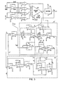
- FIG 1 is shown, in block diagram form, a head positioning system according to the present invention.
- a physical system 10 comprises the heads and disks of a disk file and a motor for moving the heads between concentric data tracks on disks in response to a motor control signal I SYS , applied to the input of the physical system.
- the disk file is of the sampled servo type wherein servo position reference information, located in sectors on the disk surface, defines the location of data tracks interspersed between the sectors. Details of the arrangement of data on the disk are shown in Figure 5.
- Information on the position of the head is thus only available at sampling times when the servo sectors pass beneath the head.
- signals from the head are-applied to a position detector 11, details of which are shown in Figures 12 and 13, which produces a sampled absolute position signal x .
- the absolute position signal is applied to a velocity detector 12, details of which are shown in Figure 15, and which also receives the motor control signal I SYS*
- the velocity detector produces a sampled velocity signal v at the sampling times.
- model system 13 shown in detail in Figure 3, which is an approximate analog of the physical system.
- the model system is responsive to a model control signal I MOD , which is normally the same as I SYS , to generate continuous high bandwidth pseudo position and velocity signals x and v m .
- I MOD model control signal
- seek controller 14 shown in detail in Figure 3, which functions in a conventional manner to produce a reference velocity signal. This signal is compared with the model velocity signal v m to produce a difference signal I V .
- the difference signal I V is applied to a summing junction 15 which also receives the output of a saturation loop within the model applied subtractively on line 16.
- the output of the saturation loop is zero for small values of I V and non-zero for larger values.
- the effect of the loop is to simulate in the model saturation of the motor driver in the physical system.
- the output of junction 15 is the model control signal I MOD which is fed back to the model system and is also applied as I SYS to control the physical system by way of a second summing junction 17.
- I SYS differs from I MOD only during track following operations, when the sampled position x p and velocity v p are fed back through a sampled compensation circuit 18 through a switch 19 to the second summing junction 17.
- I MOD is substantially zero.
- a schematic representation of the physical system 10 of Figure 1 is shown in Figure 2.
- a carriage 30 of mass M supports a read/write transducer 31 for movement radially on a magnetic recording disk 32, only a portion of which is shown.
- the disk 32 has data tracks 33, and servo sectors comprising both track identifying portions 35 and analog position reference servo tracks 36.
- the data tracks 33 are centered on the boundaries between servo tracks 36.
- the carriage 30 is driven by an electromagnetic voice coil motor 37, of motor constant K m .
- the motor coil is represented electrically by an inductance L and a resistance R.
- the motor control signal I SYS is applied to a transconductance power amplifier 38 of gain K A which provides corresponding drive current I to the motor coil.
- the electrical signals read back by transducer 31 appear on output leads 39. These signals and their further processing are shown in Figures 6 to 13.
- the model system 13 of Figure 1 is shown in detail in box 13' of Figure 3.
- Amplifier 15' corresponds to summing junction 15 of Figure 1 and receives a signal -I v from a seek controller 14' corresponding to seek controller 14 of Figure 1.
- the amplifier 15' also receives an input on line 16' for simulating the effect of saturation in the motor drive circuit.
- the output of the amplifier 15' is a current I MOD to the model which is also applied as I SYS to the physical system.
- the current I MOD is applied to an integrating amplifier 52. Since, by equation (1) above, the current of a motor is directly proportional to its acceleration, the integral of current represents velocity, in this case model velocity -v m .
- An analog switch 53 also responsive to the absence of reset pulse P 4 at a terminal 54, applies the velocity signal v m to a second integrating amplifier 55. Integration of the model velocity signal v produces the model position signal x m .
- the two integrators 52 and 55 are thus arranged to respond to a model control signal, representing motor current, by producing continuous model velocity and position signals v m and x m corresponding approximately to the velocity and position of the transducer 31 in the physical system.
- I MOD and v m are applied to a summing amplifier 60 whose output represents model power supply voltage E m .
- the model power supply voltage signal is applied to a limiter circuit comprising Zener diodes 61 and amplifier 62.
- E m When E m is below the Zener threshold it is passed unchanged to a further summing amplifier 63.
- E m exceeds the threshold the output from the limiter is equal to the threshold, E t .
- E m is applied directly to amplifier 63 where the output of limiter 62 is subtracted from it.
- I MOD is limited by a saturation modelling effect so that it cannot exceed what is attainable in the physical system.
- the model position and velocity outputs x m and v m are applied to controller 14' on lines 70 and 71.
- the line 70 is the input to a curve generator circuit for producing a desired reference velocity x from the position input x m .
- a simplified relationship between x and x m for a minimum time control strategy is:-
- the model position signal x m is amplified in a forward gain amplifier 72 of time constant T , providing the linear term.
- a high gain fast time constant feedback loop is connected around amplifier 72 to provide the square law relationship.
- is obtained by an absolute value circuit including amplifier 73 and multiplied with x in multiplier 74.
- the model position error e x is nulled in the high gain loop to produce the desired curve of velocity x vs. x . m
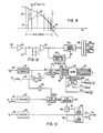
- the output curve showing the dependence of desired velocity x upon x m is the continuous line 90 in Figure 4.
- the curve is predominantly parabolic, according to the square root relationship, but includes, as indicated above, a linear portion near the origin within circle 91.
- the seek controller 14' compares the desired velocity trajectory x with the model velocity v m in summing amplifier 77.
- the difference e v between v m and x is the velocity error.
- Dashed portions 93 in Figure 4 show the model velocity v m trajectory throughout the seek motion.
- the velocity error e v is the basis of the control signal I v fed back to the model and to the physical system.
- the velocity error e is the difference in ordinate between the curves 93 and 90 in Figure 4. It can be seen that this difference is large initially and also changes abruptly as x m and v m are reset at sampling times indicated by lines 92. If e v were applied directly, high frequency components would appear at the input to the physical system which would excite high frequency mechanical resonances.
- the rate limiting circuitry comprises a limiter, including amplifier 78 and Zener diodes 79, and an integrating amplifier 80, all in a high gain fast response loop configuration.
- the output of the rate limiting circuitry is the current I v to the summing junction 15'.
- this control current I v is produced not as in conventional systems, by a comparison of actual head velocity with a desired velocity trajectory, but by a comparison of such a trajectory with a pseudo head velocity signal from a model of the physical system.
- the employment of such a model permits the use of a high bandwidth control loop in a system which has inherently low bandwidth feedback of actual position and velocity, such as the sampled servo head positioning system described.
- Figure 5 shows in expanded form the layout of data on the disk.
- This data consists of read/write data 33', analog servo data 36' and track identifying information 35'. These three types of data are located in sectors on the disk surface which are separated by gaps.
- the analog servo data consists of a pattern of odd and even servo tracks the boundaries between which coincide with the data track centres.
- head 31' When head 31' is located in the position shown in Figure 5, i.e. precisely over a data track N, it will read part of an even servo track and part of an odd one.
- the signal S A from the head 31' read back from the servo tracks is shown in Figure 6.
- the even tracks Apart from commonly aligned synchronizing dibits at the beginning of the analog servo sectors 36', the even tracks have recorded thereon four (+) unipolar dibits of one phase and the odd tracks four (-) unipolar dibits of another phase, as indicated by the plus minus signs in Figure 6.
- An analog position signal A is derived, as will be shown in Figure 13, by comparing the contributions of odd and even tracks.
- This analog position signal A of course, only represents the deviation of the head from the nearest servo track boundary and does not represent the absolute position of the head with respect to the target track as illustrated by Figure 9. During the seek motion while crossing successive tracks the analog position signal A has the form shown in Figure 7.
- the track identifying information 35' is read back by the heads as dibit signals S ID as shown, for two tracks N and N + 1 in Figures 10 and 11. Tracks are digitally identified by appropriate coding of dipulses as shown. Thus track N is coded as 011110 and track N + 1 is coded as 011111.
- the position detect circuitry comprises clock circuitry shown in Figure 12 and position signal generating circuitry shown in Figure 13.
- the clock circuitry receives at terminal 100 the composite signal from head 31, Figure 2. This consists of read/write data signals, track identifying signals S ID ( Figure 10 and 11) and analog servo signals S A ( Figure 6) repeated cyclically and with gaps in between each type of signal.
- the composite signal is amplified in video amplifier 101 and applied to a peak detect circuit in which the peak amplitude is compared with an applied reference level in comparator 102.
- the peak detector functions to detect the gaps in the composite head signal.
- the gaps are shown in waveform a of Figure 14 and are counted by binary counter 103.
- a monostable multivibrator 104 is triggered by Gap 1 and its output P1, shown in waveform b of Figure 14 is used to reset the counter to state 00 prior to the termination of the read/write data.
- the occurrence of gap 1 at the end of a read/write data sector sets the counter 103 to state 01.
- Gap 2 between the read/write and servo analog data sets the counter to state 10.
- Gap 3 between the servo analog data and track identifying data sets the counter to state 11.
- the counter outputs are decoded by decoder 105 to produce timing or gating signals on lines 106 - 109.
- a reset signal is produced on line 106 at the trailing edge of the signal P1 from the multivibrator 104 to indicate the commencement of the 00 state of counter 103.
- a servo analog gating signal P 2 waveform C of Figure 14 is produced on line 107 for the entire duration of the 01 state of the counter.
- a track identifier gating signal P 3 (waveform d of Figure 14) is produced on line 108 for the entire duration of the 10 state of the counter.
- An output reset pulse P 4 (waveform e of Figure 14) is produced by a single shot (not shown) in response to the activation of line 109 at the commencement of the 11 state of counter 103.
- the signal on line 109 corresponding to the 11 state of the counter identifies the read/write data portions of the signal which are gated by circuitry (not shown) to associated data processing apparatus.
- a signal P 5 (waveform f of Figure 14) for controlling the velocity detector circuit shown in Figure 15 is produced by delay circuitry (not shown) at the mid-point of the read/write data sectors.
- FIG. 13 The actual circuitry for generating the position signal x is shown in Figure 13 and also partly in Figure 3.
- the amplified composite head signal from output terminal 110 of Figure 12 is applied to input terminals 120 and 140.
- Input terminal 120 is connected to a first channel for deriving the track address and producing from it a digital to analog output D/A at terminal 121 corresponding to the integral number of tracks between a present position P A and a target position T A (see also Figure 9).
- Other outputs "Sgn (PA)” and “Sgn (P A -TA)" are also produced at terminals 122 and 123 respectively.
- Input terminal 140 is connected to a second channel for deriving the analog position signal A ( Figure 7) and supplying it to an output 141.
- the signal P 3 is applied by way of terminal 124 to and AND gate 125.
- the AND gate 125 also receives pulses detected from the read back signal from head 31 by pulse detect and overdrive circuit 126.
- the application of gating pulse P 3 ensures that the first channel is enabled only when the track identifying information S ID is present.
- a single shot circuit 127 responds to the trailing edges of the synchronizing pulses S in the track ID ( Figures 10 and 11) to generate a window for gating the data bits alone of the track ID into a ten bit shift register 128.
- the shift register 128 is reset before each track ID by the reset signal from output 106 of decoder 105, corresponding to the trailing edge of signal P 1 .
- the shift register output is a 10 bit Gray coded signal and is applied to a decoder 129 which converts it to binary coded decimal.
- the output of the decoder 129 is the present position P A of the head 31 in digital form.
- the lowest order output line provides the Sgn (P A ) output at terminal 122 indicating whether the track over which the head is located is odd or even.
- the digital position P A is applied to an adder 130 which also receives the target address T A as input on lines 131.
- the adder computes the difference P A -T A and outputs it on lines 132 to a digital to analog converter 133.
- the right hand line of 132 indicates the algebraic sign of the difference and is connected to terminal 123.
- the digital to analog converter converts the digital position P A of the head relative to the target track to a positive analog D/A signal which is output at terminal 121.
- the second channel of the position signal generating circuitry of Figure 13 is enabled by receipt of the gating signal P 2 at the terminal 142.
- This signal activates an oscillator 143 which produces pulses at sixteen times the frequency of the dibits of the analog servo signal S A ( Figure 6) and synchronized therewith.
- the oscillator output drives 4 bit counter 144 which together with a 4 bit comparator 145 and flip flop 146 produces gating pulses on lines 147 and 148 to separate the odd and even dibits.
- Dual peak detection circuit 149 is enabled by gating pulses on lines 147 and 148 to detect and hold the peak values of the dibits from the odd and even tracks respectively.
- the analog servo signal S A is applied to the peak detector 149 after first being rectified by rectifier 150.
- the difference between the signals from the odd and even tracks is determined by difference amplifier 151 whose output is the analog position signal A ( Figure 7).
- the four bit counter 144 is reset by the trailing output of a single shot 152, triggered by the output of pulse detector 126.
- the final portion of the position detection circuitry is shown in Figure 3.
- , Sgn (P A ) and Sgn (P A -T A ) from the circuit of Figure 13 are applied to inputs 81 to 84, respectively of a circuit including programmable amplifier 85.
- One such amplifier which is commercially available is the HA 2400.
- the amplifier produces the absolute analog position x p of the head 31 relative to the target track according to the following algorithm:-
- the first quantity represents the position to the nearest integral number of tracks with a sign determined by the direction of displacement of the head from the target track.
- the second quantity shown in Figure 8, represents the incremental deviation from the nearest track centre irrespective of whether the track is odd or even.
- the velocity detector 12' receives the position input x p from the programmable amplifier 85 ( Figure 3) at terminal 160.
- the position input x p is derived at a sampling time determined by the timing signals P 2 and P 3 , as explained in connection with Figure 6.
- the sampled position input is here expressed as xp(k) indicating that it is the kth such position sample.
- a second input to a terminal 161 is the motor control signal I SYS .
- a third input is the sampling signal P 5 at terminal 162.
- the sampling pulse P 5 occurs in the middle of each read/write data sector when xp(k) is in a steady state, and also to provide for averaging of an I SYS which may vary between samples.
- P 5 (not shown) is accomplished by timing from the trailing edge of P 3 .
- analog switches 163 and 164 are closed to connect xp(k) and I SYS to sample and hold circuits including capacitors 165 and 166 and amplifiers 167 and 168.
- the amplifier 167 provides the value xp(k-1) of the preceding sample
- the amplifier 168 provides the instantaneous value u(k-1) of the motor current related control signal I SYS at the P 5 time between the (k-l)th and kth position samples.
- the sampled velocity at the time of the kth position sample is the change in position during a fixed time interval (between samples) corrected by an acceleration factor derived from motor current.
Applications Claiming Priority (2)
| Application Number | Priority Date | Filing Date | Title |
|---|---|---|---|
| US863832 | 1977-12-23 | ||
| US05/863,832 US4133011A (en) | 1977-12-23 | 1977-12-23 | Sampled data positioning system employing a model of the physical system for time optimal control |
Publications (2)
| Publication Number | Publication Date |
|---|---|
| EP0003070A1 true EP0003070A1 (de) | 1979-07-25 |
| EP0003070B1 EP0003070B1 (de) | 1981-12-02 |
Family
ID=25341892
Family Applications (1)
| Application Number | Title | Priority Date | Filing Date |
|---|---|---|---|
| EP78300628A Expired EP0003070B1 (de) | 1977-12-23 | 1978-11-14 | Zeitoptimale digitale Steuerung zum Positionieren unter Verwendung eines Modells der Vorrichtung |
Country Status (6)
| Country | Link |
|---|---|
| US (1) | US4133011A (de) |
| EP (1) | EP0003070B1 (de) |
| JP (1) | JPS596402B2 (de) |
| CA (1) | CA1109141A (de) |
| DE (1) | DE2861419D1 (de) |
| IT (1) | IT1160328B (de) |
Cited By (6)
| Publication number | Priority date | Publication date | Assignee | Title |
|---|---|---|---|---|
| DE3016933A1 (de) * | 1980-05-02 | 1981-11-05 | Hermann Dipl.-Math. 6940 Weinheim Drösel | Digitaler servoachsen-simulator |
| EP0243821A2 (de) * | 1986-04-29 | 1987-11-04 | International Business Machines Corporation | Steuerungssystem für scheibenförmigen Aufzeichnungsträger |
| EP0113815B1 (de) * | 1982-12-20 | 1988-03-02 | International Business Machines Corporation | Servosystem für Magnetplatten |
| EP0263962A2 (de) * | 1986-10-14 | 1988-04-20 | Hewlett-Packard Company | System zur Positionierung und Spurnachfolgeregelung in einer Platteneinheit |
| EP0493035A1 (de) * | 1990-12-21 | 1992-07-01 | Fujitsu Limited | Verfahren zur Servoregelung bei einem Magnetplattengerät |
| US5286981A (en) * | 1991-06-28 | 1994-02-15 | Asea Brown Boveri Ltd. | Turn-off power semiconductor component, and also process for producing it |
Families Citing this family (42)
| Publication number | Priority date | Publication date | Assignee | Title |
|---|---|---|---|---|
| US4168457A (en) * | 1977-12-29 | 1979-09-18 | Sperry Rand Corporation | Self adaptive speed control system |
| US4246536A (en) * | 1978-09-29 | 1981-01-20 | International Business Machines Corporation | Electronic velocity measurement device |
| JPS5564661A (en) * | 1978-11-08 | 1980-05-15 | Toshiba Corp | Self-compensator for magnetic disk memory unit |
| JPS5564662A (en) * | 1978-11-08 | 1980-05-15 | Toshiba Corp | Self-compensator for magnetic disk memory unit |
| GB2039078B (en) * | 1978-12-27 | 1982-11-24 | Ibm | Sampled data servo positioning system |
| US4237502A (en) * | 1979-07-10 | 1980-12-02 | Per Sci, Inc. | Disk drive system |
| US4300174A (en) * | 1979-12-21 | 1981-11-10 | Persci, Inc. | Guard band control for magnetic disks |
| US4288731A (en) * | 1980-02-22 | 1981-09-08 | Sperry Corporation | Average value tachometer for a disc drive servo and the like |
| US4462053A (en) * | 1981-07-02 | 1984-07-24 | Irwin International, Inc. | Method for controlling a disc head |
| US4477755A (en) * | 1982-06-28 | 1984-10-16 | Storage Technology Corporation | Method of suppressing seek-excited vibration in a disk drive or similar servo system |
| JPS5984379A (ja) * | 1982-11-08 | 1984-05-16 | Nec Corp | デイスク状記録担体のトラツクアクセス装置 |
| WO1984003583A1 (en) * | 1983-03-07 | 1984-09-13 | Storage Technology Partners | System for sensing the rotational position of a rotating disk having coarse seek tracks |
| US4646635A (en) * | 1984-10-04 | 1987-03-03 | Pitney Bowes Inc. | Microprocessor controlled D.C. motor for controlling print value selection means |
| FR2594586B1 (fr) * | 1986-02-14 | 1988-04-29 | Bull Sa | Procede pour deplacer un systeme mobile par rapport a un support d'informations et dispositif pour le mettre en oeuvre |
| EP0247829A1 (de) * | 1986-05-26 | 1987-12-02 | Pioneer Electronic Corporation | Verfahren und Vorrichtung zur Korrektur der Schleifenverstärkung einer feineinstellbaren Servoschleife |
| US4697127A (en) * | 1986-06-09 | 1987-09-29 | International Business Machines Corporation | Adaptive control technique for a dynamic system |
| JPH0783625B2 (ja) * | 1987-04-03 | 1995-09-06 | 三菱電機株式会社 | 検出ヘツドの速度制御装置 |
| US4835632A (en) * | 1987-09-16 | 1989-05-30 | International Business Machines Corporation | Disk file digital servo control system with multiple sampling rate |
| US4835633A (en) * | 1987-09-16 | 1989-05-30 | International Business Machines Corporation | Disk file digital servo control system with compensation for variation in actuator acceleration factor |
| US4914644A (en) * | 1988-09-26 | 1990-04-03 | International Business Machines Corporation | Disk file digital servo control system with coil current modeling |
| US5111349A (en) * | 1989-02-07 | 1992-05-05 | Alps Electric (Usa), Inc. | Digital servo system for moving body by a distance equal to an integral multiple of a predetermined pitch |
| JP2762364B2 (ja) * | 1989-03-20 | 1998-06-04 | ファナック株式会社 | サーボモータのフィードフォワード制御方法 |
| US5038333A (en) * | 1989-05-05 | 1991-08-06 | International Business Machines Corporation | Positioning systems including reliable track crossing detection for high speed relative motions |
| US5231550A (en) * | 1990-03-12 | 1993-07-27 | Fujitsu Limited | Track access control system preventing unintentional delay in movement of head in non-adjusted disc device |
| JP2753373B2 (ja) * | 1990-04-25 | 1998-05-20 | 株式会社日立製作所 | 位置決め制御装置 |
| US5159660A (en) * | 1990-08-09 | 1992-10-27 | Western Thunder | Universal process control using artificial neural networks |
| CA2068329C (en) * | 1990-09-18 | 1998-10-13 | Ronald James Kadlec | Digital servo control system for use in disk drives |
| US5307216A (en) * | 1991-09-04 | 1994-04-26 | International Business Machines Corporation | Sector identification method and apparatus for a direct access storage device |
| US5255132A (en) * | 1991-09-04 | 1993-10-19 | International Business Machines Corporation | Adaptable clock control methods and apparatus for a direct access disk drive system |
| US5291110A (en) * | 1991-10-31 | 1994-03-01 | Integral Peripherals, Inc. | Low acoustic noise seeking method and apparatus |
| US5477103A (en) * | 1993-06-04 | 1995-12-19 | Cirrus Logic, Inc. | Sequence, timing and synchronization technique for servo system controller of a computer disk mass storage device |
| US5576910A (en) * | 1993-06-04 | 1996-11-19 | Cirrus Logic, Inc. | Burst comparison and sequential technique for determining servo control in a mass storage disk device |
| US5384524A (en) * | 1993-09-02 | 1995-01-24 | Cirrus Logic, Inc. | Voice coil motor control circuit and method for servo system control in a computer mass storage device |
| US5459624A (en) * | 1993-10-26 | 1995-10-17 | International Business Machines Corporation | Activator control method and apparatus for positioning a transducer using a phase plane trajectory trough function for a direct access storage device with estimated velocity and position states |
| JPH0973618A (ja) * | 1995-09-07 | 1997-03-18 | Toshiba Corp | ディスク記録再生装置のヘッド位置決め制御システム及びそのシステムに適用する速度制御方法 |
| JP3229204B2 (ja) * | 1996-01-26 | 2001-11-19 | シャープ株式会社 | 制御装置および情報記録再生装置 |
| KR100251924B1 (ko) * | 1996-09-02 | 2000-04-15 | 윤종용 | 탐색시 소음을 줄이기 위한 적응피이드포워드 제어방법 |
| US6088188A (en) * | 1997-02-10 | 2000-07-11 | International Business Machines Corporation | System and method for determining when hard disk drive power amplifier is saturated |
| US6219198B1 (en) | 1998-07-14 | 2001-04-17 | International Business Machines Corporation | State estimator alteration for odd sample times in a disk drive servo control system |
| KR100459721B1 (ko) * | 2002-08-31 | 2004-12-03 | 삼성전자주식회사 | 제어가능한 더미 리드 게이트를 이용한 재생방법 및 그제어장치 |
| JP4391789B2 (ja) * | 2003-10-03 | 2009-12-24 | 本田技研工業株式会社 | モデルパラメータを部分的に同定する同定器を備えた、プラントを制御する制御装置 |
| CN107257730B (zh) * | 2015-04-02 | 2019-10-22 | 惠普发展公司,有限责任合伙企业 | 基于连续模型的前馈项 |
Citations (7)
| Publication number | Priority date | Publication date | Assignee | Title |
|---|---|---|---|---|
| US3137462A (en) * | 1962-04-24 | 1964-06-16 | Honeywell Regulator Co | Control apparatus for a craft |
| US3221229A (en) * | 1962-01-22 | 1965-11-30 | Massachusetts Inst Technology | Model reference adaptive control system |
| US3601588A (en) * | 1966-05-23 | 1971-08-24 | Foxboro Co | Method and apparatus for adaptive control |
| US3758762A (en) * | 1972-07-10 | 1973-09-11 | Leeds & Northrup Co | Decoupled feedforward-feedback control system |
| US3881184A (en) * | 1974-05-28 | 1975-04-29 | Ibm | Adaptive digital servo system |
| DE2616806A1 (de) * | 1975-04-28 | 1976-11-11 | Burroughs Corp | Einrichtung zum positionieren eines lese/schreibkopfes relativ zu einem ebenen, bewegten traeger, insbesondere einer magnetspeicherplatte |
| US4030132A (en) * | 1975-03-27 | 1977-06-14 | Memorex Corporation | Dual mode velocity servo control for a linear actuator motor |
Family Cites Families (4)
| Publication number | Priority date | Publication date | Assignee | Title |
|---|---|---|---|---|
| US3427606A (en) * | 1966-03-02 | 1969-02-11 | Ibm | Memory system |
| US3657534A (en) * | 1970-03-12 | 1972-04-18 | Us Army | Digital scale for tomography and method of using same |
| US3812533A (en) * | 1972-12-22 | 1974-05-21 | Vermont Res Corp | Information storage unit transducer positioning system |
| US4056830A (en) * | 1974-03-15 | 1977-11-01 | Burroughs Corporation | Utilizing data for transducer positioning |
-
1977
- 1977-12-23 US US05/863,832 patent/US4133011A/en not_active Expired - Lifetime
-
1978
- 1978-08-15 CA CA309,372A patent/CA1109141A/en not_active Expired
- 1978-11-02 JP JP53134635A patent/JPS596402B2/ja not_active Expired
- 1978-11-14 DE DE7878300628T patent/DE2861419D1/de not_active Expired
- 1978-11-14 EP EP78300628A patent/EP0003070B1/de not_active Expired
- 1978-12-12 IT IT30729/78A patent/IT1160328B/it active
Patent Citations (7)
| Publication number | Priority date | Publication date | Assignee | Title |
|---|---|---|---|---|
| US3221229A (en) * | 1962-01-22 | 1965-11-30 | Massachusetts Inst Technology | Model reference adaptive control system |
| US3137462A (en) * | 1962-04-24 | 1964-06-16 | Honeywell Regulator Co | Control apparatus for a craft |
| US3601588A (en) * | 1966-05-23 | 1971-08-24 | Foxboro Co | Method and apparatus for adaptive control |
| US3758762A (en) * | 1972-07-10 | 1973-09-11 | Leeds & Northrup Co | Decoupled feedforward-feedback control system |
| US3881184A (en) * | 1974-05-28 | 1975-04-29 | Ibm | Adaptive digital servo system |
| US4030132A (en) * | 1975-03-27 | 1977-06-14 | Memorex Corporation | Dual mode velocity servo control for a linear actuator motor |
| DE2616806A1 (de) * | 1975-04-28 | 1976-11-11 | Burroughs Corp | Einrichtung zum positionieren eines lese/schreibkopfes relativ zu einem ebenen, bewegten traeger, insbesondere einer magnetspeicherplatte |
Non-Patent Citations (2)
| Title |
|---|
| IBM J. Res. Develop. November 1974 R.K. OSWALD "Design of a Disk File Head-Positioning Servo" * page 506 to 512 * * |
| messen, steuern, regeln 15, Vol. 9, 1972 H. LOFFLER "Zeitoptimale Steuerung industrieller Prozesse"; page 325 to 328 * introduction * * |
Cited By (9)
| Publication number | Priority date | Publication date | Assignee | Title |
|---|---|---|---|---|
| DE3016933A1 (de) * | 1980-05-02 | 1981-11-05 | Hermann Dipl.-Math. 6940 Weinheim Drösel | Digitaler servoachsen-simulator |
| EP0113815B1 (de) * | 1982-12-20 | 1988-03-02 | International Business Machines Corporation | Servosystem für Magnetplatten |
| EP0243821A2 (de) * | 1986-04-29 | 1987-11-04 | International Business Machines Corporation | Steuerungssystem für scheibenförmigen Aufzeichnungsträger |
| EP0243821A3 (en) * | 1986-04-29 | 1989-02-08 | International Business Machines Corporation | A servo control system for a data recording disk file |
| EP0263962A2 (de) * | 1986-10-14 | 1988-04-20 | Hewlett-Packard Company | System zur Positionierung und Spurnachfolgeregelung in einer Platteneinheit |
| EP0263962A3 (en) * | 1986-10-14 | 1989-05-31 | Hewlett-Packard Company | Method and apparatus for an improved sampled servo seek and track follow disc drive |
| EP0493035A1 (de) * | 1990-12-21 | 1992-07-01 | Fujitsu Limited | Verfahren zur Servoregelung bei einem Magnetplattengerät |
| US5287234A (en) * | 1990-12-21 | 1994-02-15 | Fujitsu Limited | Speed gain control based upon access time for each cylinder |
| US5286981A (en) * | 1991-06-28 | 1994-02-15 | Asea Brown Boveri Ltd. | Turn-off power semiconductor component, and also process for producing it |
Also Published As
| Publication number | Publication date |
|---|---|
| CA1109141A (en) | 1981-09-15 |
| IT7830729A0 (it) | 1978-12-12 |
| EP0003070B1 (de) | 1981-12-02 |
| US4133011A (en) | 1979-01-02 |
| JPS596402B2 (ja) | 1984-02-10 |
| JPS5487368A (en) | 1979-07-11 |
| DE2861419D1 (en) | 1982-01-28 |
| IT1160328B (it) | 1987-03-11 |
Similar Documents
| Publication | Publication Date | Title |
|---|---|---|
| EP0003070B1 (de) | Zeitoptimale digitale Steuerung zum Positionieren unter Verwendung eines Modells der Vorrichtung | |
| EP0000261B1 (de) | Schaltung zur direkten und rückgekoppelten Steuerung einer Positioniereinrichtung | |
| EP0243821B1 (de) | Steuerungssystem für scheibenförmigen Aufzeichnungsträger | |
| US4103314A (en) | Motion control system | |
| US4535372A (en) | Position tracking servo control systems and methods | |
| US4217612A (en) | Servo system for track accessing and track following in a disk drive | |
| US4835633A (en) | Disk file digital servo control system with compensation for variation in actuator acceleration factor | |
| CA1228418A (en) | Disk file servo control system with fast reduction of repeatable head position error | |
| US5917672A (en) | Disk file head positioning servo system incorporating adaptive saturated seek and head offset compensation | |
| EP0013326B1 (de) | Servo-Lageregelungssystem mit abgetasteten Positionswerten und seine Anwendung in einem Plattenspeicher mit Servo-Sektoren | |
| EP0113815B1 (de) | Servosystem für Magnetplatten | |
| US6594105B1 (en) | Time optimal seeks using linear velocity scheduling | |
| US6046878A (en) | Object positioning using discrete sliding mode control with variable parameters | |
| US5473550A (en) | Fast calibration using microsteps | |
| EP0414694A1 (de) | Abschätzung-positionierungssystem und verfahren. | |
| US4638230A (en) | Bang-bang controlled velocity command generator | |
| JPH0449187B2 (de) | ||
| CA1061461A (en) | Data storage apparatus | |
| US4377827A (en) | Servo positioning control system for a data storage apparatus | |
| JP2009217927A (ja) | 磁気記録のための磁気抵抗型読出しヘッドの滑動モード制御 | |
| JPH0136188B2 (de) | ||
| EP0103493A1 (de) | 2-Punkt-gesteuerter Geschwindigkeitsregelgenerator | |
| WO2000063753A2 (en) | Self tuning model reference controller in a disc drive | |
| US4405956A (en) | Tracking apparatus for read/write head | |
| JP3823195B2 (ja) | クロック生成装置およびディスク駆動装置 |
Legal Events
| Date | Code | Title | Description |
|---|---|---|---|
| PUAI | Public reference made under article 153(3) epc to a published international application that has entered the european phase |
Free format text: ORIGINAL CODE: 0009012 |
|
| AK | Designated contracting states |
Designated state(s): DE FR GB |
|
| 17P | Request for examination filed | ||
| GRAA | (expected) grant |
Free format text: ORIGINAL CODE: 0009210 |
|
| AK | Designated contracting states |
Designated state(s): DE FR GB |
|
| REF | Corresponds to: |
Ref document number: 2861419 Country of ref document: DE Date of ref document: 19820128 |
|
| PGFP | Annual fee paid to national office [announced via postgrant information from national office to epo] |
Ref country code: FR Payment date: 19841029 Year of fee payment: 7 |
|
| PGFP | Annual fee paid to national office [announced via postgrant information from national office to epo] |
Ref country code: DE Payment date: 19841205 Year of fee payment: 7 |
|
| PG25 | Lapsed in a contracting state [announced via postgrant information from national office to epo] |
Ref country code: GB Effective date: 19891114 |
|
| GBPC | Gb: european patent ceased through non-payment of renewal fee | ||
| PG25 | Lapsed in a contracting state [announced via postgrant information from national office to epo] |
Ref country code: FR Effective date: 19900731 |
|
| PG25 | Lapsed in a contracting state [announced via postgrant information from national office to epo] |
Ref country code: DE Effective date: 19900801 |
|
| REG | Reference to a national code |
Ref country code: FR Ref legal event code: ST |
|
| PLBE | No opposition filed within time limit |
Free format text: ORIGINAL CODE: 0009261 |
|
| STAA | Information on the status of an ep patent application or granted ep patent |
Free format text: STATUS: NO OPPOSITION FILED WITHIN TIME LIMIT |