EP0002216B1 - Reinforcing elements for reinforced earth structures - Google Patents
Reinforcing elements for reinforced earth structures Download PDFInfo
- Publication number
- EP0002216B1 EP0002216B1 EP78101398A EP78101398A EP0002216B1 EP 0002216 B1 EP0002216 B1 EP 0002216B1 EP 78101398 A EP78101398 A EP 78101398A EP 78101398 A EP78101398 A EP 78101398A EP 0002216 B1 EP0002216 B1 EP 0002216B1
- Authority
- EP
- European Patent Office
- Prior art keywords
- reinforcement
- tapes
- outer skin
- fabric
- weaves
- Prior art date
- Legal status (The legal status is an assumption and is not a legal conclusion. Google has not performed a legal analysis and makes no representation as to the accuracy of the status listed.)
- Expired
Links
- 230000003014 reinforcing effect Effects 0.000 title 1
- 239000011347 resin Substances 0.000 claims description 23
- 229920005989 resin Polymers 0.000 claims description 23
- 230000002787 reinforcement Effects 0.000 claims description 14
- 238000010276 construction Methods 0.000 claims description 8
- 230000007797 corrosion Effects 0.000 claims description 8
- 238000005260 corrosion Methods 0.000 claims description 8
- 239000012948 isocyanate Substances 0.000 claims description 4
- 150000002513 isocyanates Chemical class 0.000 claims description 4
- 229920002635 polyurethane Polymers 0.000 claims description 2
- 239000004814 polyurethane Substances 0.000 claims description 2
- 238000009435 building construction Methods 0.000 claims 1
- 150000002118 epoxides Chemical class 0.000 claims 1
- 239000004744 fabric Substances 0.000 description 23
- 239000011521 glass Substances 0.000 description 6
- 238000005470 impregnation Methods 0.000 description 6
- 229910000831 Steel Inorganic materials 0.000 description 5
- 239000010959 steel Substances 0.000 description 5
- 239000000835 fiber Substances 0.000 description 4
- 239000002689 soil Substances 0.000 description 3
- 229920000049 Carbon (fiber) Polymers 0.000 description 2
- 239000004698 Polyethylene Substances 0.000 description 2
- 238000004873 anchoring Methods 0.000 description 2
- 239000004917 carbon fiber Substances 0.000 description 2
- 239000011248 coating agent Substances 0.000 description 2
- 238000000576 coating method Methods 0.000 description 2
- 230000006378 damage Effects 0.000 description 2
- 230000000694 effects Effects 0.000 description 2
- 239000007788 liquid Substances 0.000 description 2
- 239000002184 metal Substances 0.000 description 2
- 229910052751 metal Inorganic materials 0.000 description 2
- 239000002245 particle Substances 0.000 description 2
- 239000004033 plastic Substances 0.000 description 2
- 229920003023 plastic Polymers 0.000 description 2
- -1 polyethylene Polymers 0.000 description 2
- 229920000573 polyethylene Polymers 0.000 description 2
- 239000007921 spray Substances 0.000 description 2
- 239000004593 Epoxy Substances 0.000 description 1
- 208000027418 Wounds and injury Diseases 0.000 description 1
- HCHKCACWOHOZIP-UHFFFAOYSA-N Zinc Chemical compound [Zn] HCHKCACWOHOZIP-UHFFFAOYSA-N 0.000 description 1
- 230000001070 adhesive effect Effects 0.000 description 1
- 230000005540 biological transmission Effects 0.000 description 1
- 210000001520 comb Anatomy 0.000 description 1
- 238000001723 curing Methods 0.000 description 1
- 238000005516 engineering process Methods 0.000 description 1
- 239000003365 glass fiber Substances 0.000 description 1
- 208000014674 injury Diseases 0.000 description 1
- 239000012784 inorganic fiber Substances 0.000 description 1
- 238000009434 installation Methods 0.000 description 1
- 239000000463 material Substances 0.000 description 1
- 239000000203 mixture Substances 0.000 description 1
- 238000013008 moisture curing Methods 0.000 description 1
- 239000011368 organic material Substances 0.000 description 1
- 150000003839 salts Chemical class 0.000 description 1
- 239000004576 sand Substances 0.000 description 1
- 239000007787 solid Substances 0.000 description 1
- 229910052725 zinc Inorganic materials 0.000 description 1
- 239000011701 zinc Substances 0.000 description 1
Images

Classifications
-
- E—FIXED CONSTRUCTIONS
- E02—HYDRAULIC ENGINEERING; FOUNDATIONS; SOIL SHIFTING
- E02D—FOUNDATIONS; EXCAVATIONS; EMBANKMENTS; UNDERGROUND OR UNDERWATER STRUCTURES
- E02D29/00—Independent underground or underwater structures; Retaining walls
- E02D29/02—Retaining or protecting walls
- E02D29/0225—Retaining or protecting walls comprising retention means in the backfill
- E02D29/0241—Retaining or protecting walls comprising retention means in the backfill the retention means being reinforced earth elements
-
- E—FIXED CONSTRUCTIONS
- E02—HYDRAULIC ENGINEERING; FOUNDATIONS; SOIL SHIFTING
- E02D—FOUNDATIONS; EXCAVATIONS; EMBANKMENTS; UNDERGROUND OR UNDERWATER STRUCTURES
- E02D29/00—Independent underground or underwater structures; Retaining walls
- E02D29/02—Retaining or protecting walls
- E02D29/0225—Retaining or protecting walls comprising retention means in the backfill
Definitions
- the term "reinforced earth” has become established.
- the so-called filling floor becomes a load-bearing component of the building.
- an outer skin is necessary, which can consist of metallic half-shells or plate-shaped prefabricated concrete parts, the fastening of which is described, for example, in French Pat. No. 2,221,588.
- the metal reinforcement tapes used must have a zinc coating between 26 and 56 ⁇ , whereby the imperfect cathodic edge protection for the tapes cut from galvanized sheet steel is particularly unfavorable.
- a corrosion surcharge of up to 50% of the nominal thickness required for load transfer must be made.
- Another disadvantage is that despite these measures, additional requirements must be placed on the pH value and the electrical resistance of the filling floor in order to avoid critical conditions of use for the metallic reinforcement.
- the invention has for its object to avoid the disadvantages and weak points mentioned above in the system "reinforced earth", in particular corrosion damage and to improve the friction in the earth structure. Other tasks include improving manageability and simple, secure connections between the reinforcement elements and the outer skin.
- the object is achieved in that the braided or woven tapes used are impregnated with a resin which cures only through the moisture in the filling floor.
- Another advantage that enables the high tensile strength of the reinforcement tapes to generate even higher frictional forces than with smooth or wide tapes is the friction-increasing effect of the structure of the fabric or braided tapes, which can preferably be wide-meshed and through weave (e.g. Atlas , Twill or linen weave) can be influenced.
- weave e.g. Atlas , Twill or linen weave
- the tapes according to the invention are limp, there is an extremely good adaptability to the unevenness of the filling floor when laying on the construction site, and a low risk of injury when filling the individual floor layers.
- the tapes can be coiled in great lengths, and in contrast to conventional technology, the reinforcement elements are only cut to size on the construction site, which makes transportation and laying much cheaper.
- the warp-reinforced fabric preferably consists of high-strength inorganic fibers, for example of glass fibers or of carbon fibers or of fiber mixtures of the fibers mentioned, which are impregnated with liquid reactive resins.
- These fabric tapes preferably have basis weights between 400 and 800 g / m 2 .
- Suitable reaction resins are, for example, epoxy, polyurethane or isocyanate resins.
- the pre-impregnation of the fabric belts can be in impregnation baths between rollers, which can be attached directly in front of the take-off device by a suitable reel, respectively.
- the dosage of the reaction resin is not critical; the fabric tape only has to be completely wetted.
- the breaking load of the fabric tapes does not depend on the resin content of the impregnation. It may also be advantageous to lay the load-bearing fabric tapes dry and to spray or spray the liquid reaction resin onto the fabric tapes before filling them with the friction floor.
- the pre-impregnated tapes which only need to be laid out on the construction site, are hardened after laying out by the moisture in the filling floor.
- the curing time can be set within wide limits; Advantageous settings allow for laying time between 15 minutes and 2 hours.
- the installed belt adapts well to uneven floors due to its flexibility; the friction bond between the belt and the soil is further improved by the reaction resin as a result of the earth particles adhering to the fabric belt, thus achieving a strong load-bearing capacity for the soil surrounding the belt.
- the reaction resin After the reaction resin has hardened, the tape is dimensionally stable and has a considerable pull-out resistance.
- suitable reactive resins leads to outstanding corrosion resistance; the already good per se resistance of the glass l and carbon fibers is increased even further by coating with reactive resins.
- the moisture in the filling floor can be used to harden these resins.
- the fabric tapes are perfectly hardened even in unfavorable weather conditions during installation.
- the amount of resin used for impregnation is not critical, since the reinforcement fabric reaches its calculated breaking load regardless of the amount of resin impregnated.
- the flexible bands can be laid in a hairpin-shaped manner, for example in the earthworks, the open ends of the band being directed into the earthworks and the loop being carried by a bracket which is attached to the outer skin of the structure and thus the non-positive connection between the outer skin and the reinforcement band manufactures.
- Another possibility for the non-positive connection of the fabric straps to the outer skin of the building is to place the straps in a loop around the strap on the outer skin and to secure the loop with a suitable closure, e.g. secure one or more clamps by friction.
- connection in such a way that one or more overlapping loops are formed over the bracket for the introduction of force in the outer skin of the earth structure, which form the load-bearing connection through the hardening of the reaction resin.
- Figure 1 shows warp-reinforced fabric tape in linen weave. It consists of 5 glass rovings as warp threads 1 and glass spun threads of the weft thread 2 with a load capacity of approximately 12 kN and a width of approximately 60 mm. Similar glass fabric tapes are commercially available, for example, as types RLS 304016 or RLS 4022 from A. Weng, Holzhausen or under the designation 94025 from Intergfas Textil GmbH, with which breaking loads between 6 and 15 kN can be achieved.
- FIG. 2 shows a laboratory product made from a ribbon braid.
- the warp tape 3 is highly stretched polyethylene, the thickness is 100 11 , the width is about 5 mm.
- the weft tape 4 is made of polyethylene, has a width of 0.2 mm and is 50 u thick.
- the width of the finished braid of 5 tapes is 50 mm, the thickness about 0.8 mm.
- the breaking load of this band is 9.7 kN.
- the pre-impregnated band 10 consists of stretched organic fibers. It is laid out on the filling base 11, placed in a loop 12 around the plastic-coated support tube 13 and anchored non-positively by stretched combs 14.
- a pre-impregnated fabric tape 15 made of glass silk is placed around the plastic-coated steel tube 17, which is encased in concrete in the outer skin 16; when pulling off a reel, the belt 15 is passed through an impregnation bath with a moisture-curing isocyanate resin with an NCO content of approx. 16% and a viscosity of approx. 5000 mPas and, after impregnation, is laid directly on the filling floor 18 in the manner shown, a provisional securing of the overlap of the strip end is carried out by U-shaped clamps made of ABS. Under normal conditions, the reaction resin is solid after 50 minutes and the connection to the outer skin of the earth structure is fully resilient.
Landscapes
- Engineering & Computer Science (AREA)
- Civil Engineering (AREA)
- Life Sciences & Earth Sciences (AREA)
- General Life Sciences & Earth Sciences (AREA)
- Mining & Mineral Resources (AREA)
- Paleontology (AREA)
- Environmental & Geological Engineering (AREA)
- General Engineering & Computer Science (AREA)
- Structural Engineering (AREA)
- Reinforced Plastic Materials (AREA)
- Bridges Or Land Bridges (AREA)
- Revetment (AREA)
- Pit Excavations, Shoring, Fill Or Stabilisation Of Slopes (AREA)
- Woven Fabrics (AREA)
Description
Für Stützbauwerke, bei denen in einem kohäsionslosen Boden regelmäßig und lagenweise Metallbänder eingelegt werden, die Zugkräfte aufnehmen und diese über Reibung in den Boden abtragen, hat sich der Begriff "Bewehrte Erde"eingebürgert. Der sogenannte Füllboden wird zum tragenden Bestandteil des Bauwerks. Um zu verhindern, daß sich der Füllboden abböscht ist eine Außenhaut notwendig, die aus metallischen Halbschalen oder plattenförmigen Betonfertigteilen bestehen kann, deren Befestigung beispielsweise in der FR - PS 2 221 588 beschrieben ist. Über "Bewehrte Erde" wird beispielsweise in "Straße und Autobahn" 5 (1976) 3/10, "Tiefbau" 8 und 9 (1976) oder "Die Bautechnik" 53 (1976) 7, 217/226 berichtet. Zur Verankerung von Matten oder Bändern im Erdbereich werden in der FR - PS 2 234 427 Vorschläge gemacht.For supporting structures in which metal strips are regularly and layered inserted in a non-cohesive floor, which absorb tensile forces and dissipate them into the ground through friction, the term "reinforced earth" has become established. The so-called filling floor becomes a load-bearing component of the building. In order to prevent the filling base from being bent off, an outer skin is necessary, which can consist of metallic half-shells or plate-shaped prefabricated concrete parts, the fastening of which is described, for example, in French Pat. No. 2,221,588. For example, "Reinforced Earth" is reported in "Straße und Autobahn" 5 (1976) 3/10, "Tiefbau" 8 and 9 (1976) or "Die Bautechnik" 53 (1976) 7, 217/226. Proposals are made in FR - PS 2 234 427 for anchoring mats or tapes in the ground.
Aus Korrosionsgründen müssen die eingesetzten metallischen Bewehrungsbänder eine Zinkauflage zwischen 26 und 56 µ aufweisen, wobei besonders ungünstig der unvollkommene katodische Kantenschutz bei den Bändern ist, die aus verzinktem Stahlblech geschnitten werden. Hinzu kommt, daß aus Sicherheitsgründen ein Korrosionszuschlag von bis zu 50% der für die Lastübertragung erforderlichen Nenndicke gemacht werden muß. Ebenso nachteilig ist, daß trotz dieser Maßnahmen noch zusätzliche Anforderungen an den pH-Wert und den elektrischen Durchgangswiderstand des Füllbodens gestellt werden müssen, um kritische Einsatzbedingungen für die metallische Bewehrung zu vermeiden.For corrosion reasons, the metal reinforcement tapes used must have a zinc coating between 26 and 56 µ, whereby the imperfect cathodic edge protection for the tapes cut from galvanized sheet steel is particularly unfavorable. In addition, for safety reasons, a corrosion surcharge of up to 50% of the nominal thickness required for load transfer must be made. Another disadvantage is that despite these measures, additional requirements must be placed on the pH value and the electrical resistance of the filling floor in order to avoid critical conditions of use for the metallic reinforcement.
Diese Maßnahmen begrenzen die aus Gründen der erwünschten hohen Reibungskräfte flächige Ausgestaltung der Bänder mit hohem Verhältnis von Oberfläche zur Querschnittsfläche, wodurch die Übertragung der Reibungskräfte zu klein werden kann. Zur Verbesserung des Haftvermögens von Stahlbändern sind aufwendige, gewalzte Profile mit Querrippen unterschiedlicher Ausprägung wie Bogenrippen, schräglaufende oder gepfeilte Rippen vorgeschlagen worden.These measures limit the flat design of the strips with a high ratio of surface to cross-sectional area for reasons of the desired high frictional forces, as a result of which the transmission of the frictional forces can become too small. In order to improve the adhesive properties of steel strips, complex, rolled profiles with cross ribs of various types, such as curved ribs, oblique ribs or swept ribs, have been proposed.
Wegen der besonders kritischen Korrosionsverhältnisse in Spalten sind auch die vorgeschlagenen Schraubverbindungen oder Bolzenverbindungen für die Verbindung zwischen der Außenhaut des Bauwerks und den Bewehrungsbändern oder zwischen den Bewehrungsbändern untereinander störungsanfällig. Die Verwerdung korrosionsgeschützter Schrauben und Scheiben, wie sie die vorläufigen Richtlinien der Bundesanstalt für Straßenwesen für die Anwendung des Bauverfahrens "Bewehrte Erde" vorschreiben, ist insbesondere in Tausalzgefährdeten Bereichen problematisch.Because of the particularly critical corrosion conditions in gaps, the proposed screw connections or bolt connections for the connection between the outer skin of the building and the reinforcement strips or between the reinforcement strips are also susceptible to failure. The use of corrosion-protected screws and washers, as prescribed by the provisional guidelines of the Federal Highway Research Institute for the use of the "reinforced earth" construction method, is particularly problematic in areas exposed to de-icing salt.
Die Erfindung liegt die Aufgabe zugrunde, die oben erwähnten Nachteile und Schwachpunkte am System "Bewehrte Erde", insbesondere Korrosionsschäden zu vermeiden und die Reibungsverhältnisse im Erdbauwerk zu verbessern. Weitere Aufgaben sind die Verbesserung der Handhabbarkeit und einfache sichere Verbindungen der Bewehrungselemente mit der Außenhaut. Die Aufgabe wird dadurch gelöst, daß die verwendeten Flecht- oder Gewebebänder mit einem Harz imprägniert sind, das erst durch die Feuchtigkeit des Füllbodens aushärtet.The invention has for its object to avoid the disadvantages and weak points mentioned above in the system "reinforced earth", in particular corrosion damage and to improve the friction in the earth structure. Other tasks include improving manageability and simple, secure connections between the reinforcement elements and the outer skin. The object is achieved in that the braided or woven tapes used are impregnated with a resin which cures only through the moisture in the filling floor.
Entsprechend der Erfindung wird vorgeschlagen, als Bewehrungselemente korrosionsbeständige, hochfeste gewebte oder geflochtene Bänder zu verwenden. Mit vorwiegend kettverstärkten Geweben oder Geflechten aus verstreckten organischen Fasern lassen sich bereits die Festigkeiten der üblicherweise eingesetzten Baustähle erreichen, wobei die Gewebe oder Geflechte allein durch die Auswahl geeigneter Grundwerkstoffe bereits als weitgehend korrosionsbeständig angesehen werden können. Deswegen ist es möglich, entsprechend breite und dünne Bänder zu verwenden, die durch ein hohes Verhältnis von Umfang zu Querschnitt es allein aufgrund ihrer großen Oberflächen gestatten, hohe Reibungskräfte ohne besondere Hilfsmittel zur Erhöhung der Reibung, wie z.B. Rippen, in den Boden abzutragen. Ein weiterer Vorteil, der es bei der hohen Zugfestigkeit der Bewehrungsbänder ermöglicht, noch höhere Reibungskräfte als bei glatten oder breiten Bändern zu erzeugen, liegt in dem reibungserhöhenden Effekt der Struktur der Gewebe oder Flechtbänder, die bevorzugt weitmaschig sein kann und durch Webart (z.B. Atlas-, Köper- oder Leinenbindung) beeinflußt werden kann.According to the invention, it is proposed to use corrosion-resistant, high-strength woven or braided tapes as reinforcement elements. With predominantly warp-reinforced fabrics or braids made from stretched organic fibers, the strengths of the structural steels normally used can already be achieved, the fabrics or braids being able to be regarded as largely corrosion-resistant simply by selecting suitable base materials. Therefore, it is possible to use correspondingly wide and thin belts, which due to a high ratio of circumference to cross-section, due to their large surfaces alone, allow high frictional forces without special aids to increase the friction, e.g. Ribs to dig into the ground. Another advantage that enables the high tensile strength of the reinforcement tapes to generate even higher frictional forces than with smooth or wide tapes is the friction-increasing effect of the structure of the fabric or braided tapes, which can preferably be wide-meshed and through weave (e.g. Atlas , Twill or linen weave) can be influenced.
Weil die erfindungsgemäßen Bänder biegeschlaff sind, ergibt sich beim Verlegen auf der Baustelle eine äußerst gute Anpassungsfähigkeit an die Unebenheiten des Füllbodens, sowie eine geringe Verletzungsgefahr beim Verfüllen der einzelnen Bodenschichten. Die Bänder können in großen Längen aufgehaspelt sein, und im Gegensatz zur üblichen Technik werden die Armierungselemente erst auf der Baustelle zugeschnitten, was den Transport und das Verlegen sehr verbilligt.Because the tapes according to the invention are limp, there is an extremely good adaptability to the unevenness of the filling floor when laying on the construction site, and a low risk of injury when filling the individual floor layers. The tapes can be coiled in great lengths, and in contrast to conventional technology, the reinforcement elements are only cut to size on the construction site, which makes transportation and laying much cheaper.
Bei den Bewehrungsbändern besteht das kettverstärkte Gewebe bevorzugt aus hochfesten anorganischen Fasern, beispielsweise aus Glasfasern oder aus Kohlenstoffasern oder aus Fasergemischen der genannten Fasern, die mit flüssigen Reaktionsharzen getränkt sind. Diese Gewebebänder weisen bevorzugt Flächengewichte zwischen 400 und 800 g/m2 auf. Als Reaktionsharze sind beispielsweise Epoxid-, Polyurethan- oder Isocyanatharze geeignet. Die Vorimprägnierung der Gewebebänder kann in Tränkbädern zwischen Walzen, die direkt vor der Abzugsvorrichtung von einer geeigneten Haspel angebracht sein können, erfolgen. Die Dosierung des Reaktionsharzes ist unkritisch; das Gewebeband muß nur vollständig benetzt sein. Die Bruchlast der Gewebebänder hängt nicht vom Harzanteil der Imprägnierung ab. Es kann auch vorteilhaft sein, die tragenden Gewebebänder trocken zu verlegen und das flüssige Reaktionsharz vor dem Verfüllen mit dem Reibungsboden auf die Gewebebänder aufzuspritzen oder aufzusprühen. Die Aushärtung der vorimprägnierten Bänder, die auf der Baustelle nur ausgelegt werden müssen, erfolgt nach dem Auslegen durch die Feuchtigkeit des Füllbodens. Die Härtungszeit kann in weiten Grenzen eingestellt werden; vorteilhafte Enstellungen ermöglichen einen Verlegungsspielraum zwischen 15 Minuten und 2 Stunden.In the case of the reinforcement tapes, the warp-reinforced fabric preferably consists of high-strength inorganic fibers, for example of glass fibers or of carbon fibers or of fiber mixtures of the fibers mentioned, which are impregnated with liquid reactive resins. These fabric tapes preferably have basis weights between 400 and 800 g / m 2 . Suitable reaction resins are, for example, epoxy, polyurethane or isocyanate resins. The pre-impregnation of the fabric belts can be in impregnation baths between rollers, which can be attached directly in front of the take-off device by a suitable reel, respectively. The dosage of the reaction resin is not critical; the fabric tape only has to be completely wetted. The breaking load of the fabric tapes does not depend on the resin content of the impregnation. It may also be advantageous to lay the load-bearing fabric tapes dry and to spray or spray the liquid reaction resin onto the fabric tapes before filling them with the friction floor. The pre-impregnated tapes, which only need to be laid out on the construction site, are hardened after laying out by the moisture in the filling floor. The curing time can be set within wide limits; Advantageous settings allow for laying time between 15 minutes and 2 hours.
Im Gegensatz zu Stahlbändern paßt sich das verlegte Band aufgrund seiner Flexibilität den Bodenunebenheiten gut an; der Reibungsverbund zwischen Band und Erdreich wird durch das Reaktionsharz infolge der an dem Gewebeband anhaftenden Erdteilchen noch verbessert und so eine starke Tragwirkung des das Band umgebenden Bodens erzielt. Nach dem Erhärten des Reaktionsharzes ist das Band formsteif und hat einen erheblichen Ausziehwiderstand. Die Verwendung geigneter Reaktionsharze führt zu einer überragenden Korrosionsbeständigkeit; die an sich bereits gute Beständigkeit der Glas-l und Kohlenstoffasern wird durch die Umhüllung mit Reaktionsharzen noch weiter erhöht.In contrast to steel belts, the installed belt adapts well to uneven floors due to its flexibility; the friction bond between the belt and the soil is further improved by the reaction resin as a result of the earth particles adhering to the fabric belt, thus achieving a strong load-bearing capacity for the soil surrounding the belt. After the reaction resin has hardened, the tape is dimensionally stable and has a considerable pull-out resistance. The use of suitable reactive resins leads to outstanding corrosion resistance; the already good per se resistance of the glass l and carbon fibers is increased even further by coating with reactive resins.
Besonders bei Imprägnierung der Gewebebänder mit Isocyanatharzen kann die Feuchtigkeit des Füllbodens zur Härtung dieser Harze genutzt werden. Auch bei ungünstigen Witterungsbedingungen bei der Verlegung werden die Gewebebänder einwandfrei gehärtet. Für den Baustellenbetrieb ist es auch vorteilhaft, daß die Harzmenge zur Tränkung unkritisch ist, da der Festigkeitsträger Gewebe unabhängig von der Imprägniermenge an Harz seine rechnerische Bruchlast erreicht.Especially when the fabric tapes are impregnated with isocyanate resins, the moisture in the filling floor can be used to harden these resins. The fabric tapes are perfectly hardened even in unfavorable weather conditions during installation. For construction site operation, it is also advantageous that the amount of resin used for impregnation is not critical, since the reinforcement fabric reaches its calculated breaking load regardless of the amount of resin impregnated.
Die Krafteinleitung in Gewebe- oder Geflechtbänder ist sicher und einfach zu handhaben. Zur Krafteinleitung können die flexiblen Bänder beispielsweise im Erdbauwerk haarnadelförmig verlegt werden, wobei die offenen Enden des Bandes in das Erdbauwerk hineingerichtet sind und die Schlaufe von einem Bügel getragen wird, der an der Außenhaut des Bauwerks angebracht ist und so die kraftschlüssige Verbindung zwischen Außenhaut und Bewehrungsband herstellt. Eine andere Möglichkeit zum kraftschlüssigen Anschluß der Gewebebänder an die Außenhaut des Bauwerks besteht darin, die Bänder in einer Schlaufe um den Bügel an der Außenhaut zu legen und die Schlaufe mit einem geeigneten Verschluß, z.B. einer oder mehrerer Klemmen durch Reibung zu sichern. Es ist besonders günstig, eine Anschlußart in der Weise vorzusehen, daß eine oder mehrere einander überlappende Schlaufen über den Bügel zur Krafteinleitung in der Außenhaut des Erdbauwerks geformt werden, die durch das Erhärten des Reaktionsharzes die tragende Verbindung bilden. Eine zusätzliche Fixierung der einzelnen Lagen der Gewebebänder durch Bügelverschlüsse erhöht die Handhabungssicherheit dieser Verbindung erheblich und ermöglicht hohe Zugbelastungen bereits vor dem Aushärten des Reaktionsharzes.The application of force in fabric or braid tapes is safe and easy to use. To apply force, the flexible bands can be laid in a hairpin-shaped manner, for example in the earthworks, the open ends of the band being directed into the earthworks and the loop being carried by a bracket which is attached to the outer skin of the structure and thus the non-positive connection between the outer skin and the reinforcement band manufactures. Another possibility for the non-positive connection of the fabric straps to the outer skin of the building is to place the straps in a loop around the strap on the outer skin and to secure the loop with a suitable closure, e.g. secure one or more clamps by friction. It is particularly expedient to provide a type of connection in such a way that one or more overlapping loops are formed over the bracket for the introduction of force in the outer skin of the earth structure, which form the load-bearing connection through the hardening of the reaction resin. An additional fixation of the individual layers of the fabric tapes by means of clip closures increases the handling security of this connection considerably and enables high tensile loads even before the reaction resin hardens.
Die Erfindung ist in den Figuren beispielhaft dargestellt und im folgenden näher erläutert. Es zeigen:
- Figur 1 ein kettverstärktes Gewebeband in Leinenbindung;
- Figur 2 ein Geflecht mit Bändchen aus verstreckten organischen Werkstoffen;
Figur 3 eine kraftschlüssige Verbindung über einen Reibungsverschluß;Figur 4 ein imprägniertes Gewebeband aus Glasseide;- Figur 5 schematische Darstellung des Effektes der Reibungserhöhung.
- Figure 1 is a warp-reinforced fabric tape in linen weave;
- FIG. 2 shows a braid with ribbons made from stretched organic materials;
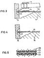
- Figure 3 shows a frictional connection via a friction lock;
- Figure 4 is an impregnated fabric tape made of glass silk;
- Figure 5 shows a schematic representation of the effect of increasing the friction.
In Figure 1 ist kettverstärktes Gewebeband in Leinenbindung dargestellt. Es besteht aus 5 Glasrovings als Kettfäden 1 und Glasspinnfäden des Schußfadens 2 mit einer Tragfähigkeit von etwa 12 kN bei einer Breite von etwa 60 mm. Ähnliche Glasgewebebänder sind beispielsweise als Typen RLS 304016 bzw. RLS 4022 der Fa. A. Weng, Holzhausen oder unter der Bezeichnung 94025 der Fa. Intergfas Textil GmbH im Handel, mit denen Bruchlasten zwischen 6 und 15 kN erreicht werden.Figure 1 shows warp-reinforced fabric tape in linen weave. It consists of 5 glass rovings as warp threads 1 and glass spun threads of the weft thread 2 with a load capacity of approximately 12 kN and a width of approximately 60 mm. Similar glass fabric tapes are commercially available, for example, as types RLS 304016 or RLS 4022 from A. Weng, Holzhausen or under the designation 94025 from Intergfas Textil GmbH, with which breaking loads between 6 and 15 kN can be achieved.
In Figur 2 ist ein Laborprodukt aus einem Bändchengeflecht dargestellt. Das Kettband 3 ist hochverstrecktes Polyäthylen, die Dicke beträgt 100 11, die Breite ca. 5 mm. Das Schußband 4 besteht aus Polyäthylen, hat eine Breite von 0,2 mm und ist 50 u dick. Die Breite des fertigen Geflechts aus 5 Bändern beträgt 50 mm, die Dicke etwa 0,8 mm. Die Bruchlast dieses Bandes liegt bei 9,7 kN.FIG. 2 shows a laboratory product made from a ribbon braid. The
In Figur 3 ist eine Möglichkeit der Verankerung der Außenhaut 9 dargestellt. Das vorimprägnierte Band 10 besteht in diesem Fall aus verstreckten organischen Fasern. Es wird auf dem Füllboden 11 ausgelegt, in einer Schlaufe 12 um das kunststoffbeschichtete Tragrohr 13 gelegt und durch aufgestreckte Kämme 14 kraftschlüssig verankert.A possibility of anchoring the outer skin 9 is shown in FIG. In this case, the
In Figur 4 wird ein vorimprägniertes Gewebeband 15 aus Glasseide um das in der Außenhaut 16 einbetonierte kunststoffummantelte Stahlrohr 17 gelegt; beim Abziehen von einer Haspel wird das Band 15 durch ein Imprägnierbad mit einem feuchtigkeitshärtenden lsocyanatharz mit einem NCO-Gehalt von ca. 16% bei einer Viskosität von ca. 5000 mPas geführt und nach dem Imprägnieren unmittelbar in der dargestellten Weise auf den Füllboden 18 verlegt, wobei eine vorläufige Sicherung der Überlappung des Bandendes durch aufgesteckte U-förmige Klemmen aus ABS erfolgt. Unter üblichen Bedingungen ist nach 50 Minuten das Reaktionsharz fest und die Verbindung mit der Außenhaut des Erdbauwerks voll belastbar.In FIG. 4, a
In Figur 5 ist die erhöhte Tragwirkung getränkter Bänder schematisch dargestellt. An dem imprägnierten Gewebeband 22 haften Erd-und Sandpartikel 23 und erhöhen die Reibung im lockeren Erdreich 24.In Figure 5, the increased load-bearing capacity of impregnated tapes is shown schematically. At Earth and
Claims (3)
Applications Claiming Priority (2)
| Application Number | Priority Date | Filing Date | Title |
|---|---|---|---|
| DE19772753243 DE2753243A1 (en) | 1977-11-29 | 1977-11-29 | REINFORCEMENT OF REINFORCED EARTH STRUCTURES |
| DE2753243 | 1977-11-29 |
Publications (2)
| Publication Number | Publication Date |
|---|---|
| EP0002216A1 EP0002216A1 (en) | 1979-06-13 |
| EP0002216B1 true EP0002216B1 (en) | 1980-12-10 |
Family
ID=6024900
Family Applications (1)
| Application Number | Title | Priority Date | Filing Date |
|---|---|---|---|
| EP78101398A Expired EP0002216B1 (en) | 1977-11-29 | 1978-11-18 | Reinforcing elements for reinforced earth structures |
Country Status (6)
| Country | Link |
|---|---|
| US (1) | US4273476A (en) |
| EP (1) | EP0002216B1 (en) |
| JP (1) | JPS54107105A (en) |
| AT (1) | AT362307B (en) |
| DE (2) | DE2753243A1 (en) |
| IT (1) | IT1100763B (en) |
Families Citing this family (52)
| Publication number | Priority date | Publication date | Assignee | Title |
|---|---|---|---|---|
| US4324508A (en) * | 1980-01-09 | 1982-04-13 | Hilfiker Pipe Co. | Retaining and reinforcement system method and apparatus for earthen formations |
| FR2537180B1 (en) * | 1982-12-06 | 1987-01-30 | Vidal Henri | DECK BUILDING BUILT IN STABILIZED EARTH |
| EP0130949A3 (en) * | 1983-06-28 | 1985-11-27 | Luciano Sangiorgio | Concrete panels and relative means for their anchoring to earth, for forming a facing wall of variable planimetric course and allowing settlement of the panels in the facing wall surface, and the facing wall thus obtained |
| SE439793B (en) * | 1983-10-21 | 1985-07-01 | Bjorn Magnus Ringesten Med Fir | PROCEDURE THROUGH COMPENSATION BASIS ASTADKOMMA BASIC AND / OR BASIC REINFORCEMENT |
| DE3344974A1 (en) * | 1983-12-13 | 1985-06-20 | Kronimus & Sohn Betonsteinwerk und Baugeschäft GmbH & Co KG, 7551 Iffezheim | BOOTHING STONE AND METHOD FOR BUILDING UP A HANGING FASTENING THEREFORE |
| US4616959A (en) * | 1985-03-25 | 1986-10-14 | Hilfiker Pipe Co. | Seawall using earth reinforcing mats |
| DE3516969C2 (en) * | 1985-05-10 | 1995-05-24 | Hans Reinschuetz | Plantable support structure |
| US4627133A (en) * | 1985-08-08 | 1986-12-09 | Owens-Corning Fiberglas Corporation | Pultruded underground tank hold-down strap assembly |
| DE3687345T2 (en) * | 1985-12-26 | 1993-07-29 | Shimizu Construction Co Ltd | CONCRETE REINFORCEMENT UNIT. |
| CA1243497A (en) * | 1986-01-15 | 1988-10-25 | Hugh G. Wilson | Retaining wall structure |
| GB2199063B (en) * | 1986-12-18 | 1990-09-26 | Mccauley Corp Ltd | Retaining wall system |
| US4992003A (en) * | 1989-01-16 | 1991-02-12 | Yehuda Welded Mesh Ltd. | Unit comprising mesh combined with geotextile |
| DE3913335A1 (en) * | 1989-04-22 | 1990-10-25 | Rolf Hoelzer | WALL |
| CA2017578C (en) * | 1990-05-25 | 1997-12-23 | Angelo Risi | Embankment reinforcing structures |
| DE4131423A1 (en) * | 1991-09-20 | 1993-03-25 | Sf Vollverbundstein | CONSTRUCTION KIT OF CONCRETE SHAPED STONES AND A HEAVYWEIGHT SUPPORT WALL MADE THEREOF |
| US5588783A (en) * | 1992-05-08 | 1996-12-31 | The United States Of America As Represented By The Secretary Of The Army | Soil reinforcement with adhesive-coated fibers |
| ES2135493T3 (en) | 1992-10-06 | 1999-11-01 | Anchor Wall Syst | A COMPOSITE MASONRY BLOCK. |
| GB9226143D0 (en) * | 1992-12-15 | 1993-02-10 | Martin Christopher | Method of connecting geogrids to retaining walls or boundary structures |
| EP0707117B1 (en) * | 1993-03-31 | 2002-07-10 | Société Civile des Brevets Henri Vidal | Modular block retaining wall construction |
| US5807030A (en) * | 1993-03-31 | 1998-09-15 | The Reinforced Earth Company | Stabilizing elements for mechanically stabilized earthen structure |
| US5507599A (en) * | 1993-03-31 | 1996-04-16 | Societe Civile Des Brevets Henri C. Vidal | Modular block retaining wall construction and components |
| GB9313095D0 (en) * | 1993-06-24 | 1993-08-11 | Vidal Henri Brevets | Earth structures |
| US5522682A (en) * | 1994-03-02 | 1996-06-04 | The Tensar Corporation | Modular wall block system and grid connection device for use therewith |
| US5540525A (en) * | 1994-06-06 | 1996-07-30 | The Tensar Corporation | Modular block retaining wall system and method of constructing same |
| US5595460A (en) * | 1994-06-06 | 1997-01-21 | The Tensar Corporation | Modular block retaining wall system and method of constructing same |
| GB9417507D0 (en) * | 1994-08-31 | 1994-10-19 | E C Civil Eng Ltd | Reinforcement device |
| US5839855A (en) * | 1995-08-18 | 1998-11-24 | Societe Civile Des Brevets Henri C. Vidal | Facing element for a stabilized earth structure |
| DE29605181U1 (en) * | 1996-03-20 | 1996-08-29 | Wilhelm Siemsen Gmbh U Co Kg | Anchored angle support wall |
| GB9607782D0 (en) * | 1996-04-15 | 1996-06-19 | Vidal Henri Brevets | Earth structures |
| US5816749A (en) * | 1996-09-19 | 1998-10-06 | The Tensar Corporation | Modular block retaining wall system |
| DE19731946A1 (en) * | 1997-07-24 | 1999-01-28 | Roblon As | Fastening device for pipes and other objects and method for their production |
| US6368024B2 (en) | 1998-09-29 | 2002-04-09 | Certainteed Corporation | Geotextile fabric |
| TW457317B (en) * | 1998-11-06 | 2001-10-01 | Bridgestone Corp | Resin net and its production method, and drawn product of polyethylene based resin |
| US6315499B1 (en) | 1999-04-01 | 2001-11-13 | Saint Cobain Technical Fabrics Canada, Ltd. | Geotextile fabric |
| EP1250222A4 (en) * | 2000-01-05 | 2003-04-16 | Saint Gobain Technical Fabrics | Smooth reinforced cementitious boards and methods of making same |
| FR2803610B1 (en) * | 2000-01-07 | 2002-09-27 | Freyssinet Int Stup | SYSTEM FOR ATTACHING A REINFORCEMENT STRIP TO A WALL OF A SUPPORT STRUCTURE AND DEVICE FOR LAYING SAID SYSTEM |
| FR2816647B1 (en) | 2000-11-15 | 2003-01-17 | Gtm Construction | FACING FOR REINFORCED LAND WORK |
| FR2816648B1 (en) | 2000-11-15 | 2003-08-08 | Gtm Construction | REINFORCED EARTH STRUCTURE |
| US7096635B2 (en) | 2001-03-02 | 2006-08-29 | Rockwood Retaining Walls, Inc. | Multiuse block and retaining wall |
| US6692195B2 (en) * | 2001-10-25 | 2004-02-17 | Jan Erik Jansson | Plantable noise abatement wall |
| US7049251B2 (en) * | 2003-01-21 | 2006-05-23 | Saint-Gobain Technical Fabrics Canada Ltd | Facing material with controlled porosity for construction boards |
| KR100660356B1 (en) * | 2004-10-19 | 2006-12-21 | 이정수 | reinforcing strip for supporting reinforced earth wall and its placement method |
| FR2878268B1 (en) * | 2004-11-25 | 2007-02-09 | Freyssinet Internat Stup Soc P | REINFORCED GROUND WORK AND FACING ELEMENTS FOR ITS CONSTRUCTION |
| US7351015B2 (en) | 2005-10-11 | 2008-04-01 | Mortarless Technologies, Llc | Invertible retaining wall block |
| FR2913436B1 (en) * | 2007-03-05 | 2009-05-29 | Terre Armee Internationale Soc | REINFORCED GROUND WORK AND REINFORCING ELEMENTS FOR ITS CONSTRUCTION |
| FR2939157B1 (en) * | 2008-12-02 | 2013-02-15 | Terre Armee Int | REINFORCED GROUND WORK AND FACING ELEMENTS FOR ITS CONSTRUCTION |
| US20100215442A1 (en) * | 2009-02-26 | 2010-08-26 | Ackerstein Industries | Retaining wall stabilization system |
| EP2372027B1 (en) * | 2010-04-02 | 2012-11-14 | Terre Armée Internationale | Facing element for use in a stabilized soil structure |
| US20140345220A1 (en) * | 2013-05-24 | 2014-11-27 | Francesco Ferraiolo | Anchoring system for concrete panels in a stabilized earth structure |
| US20150078838A1 (en) * | 2013-09-18 | 2015-03-19 | Kenneth Shaw | Horizontal connection for mechanically stabilized earth walls |
| AU2016364021B2 (en) * | 2015-12-03 | 2022-05-26 | Maurice Andrew FRASER | Void former |
| US20220220691A1 (en) * | 2021-01-08 | 2022-07-14 | Earth Wall Products, Llc | Mechanically stabilized earth (mse) retaining wall employing geosynthetic strip with plastic pipe(s) around steel rod |
Family Cites Families (14)
| Publication number | Priority date | Publication date | Assignee | Title |
|---|---|---|---|---|
| CA656062A (en) * | 1963-01-15 | J. Coakley Alfred | Underground sheeting methods | |
| FR1393988A (en) * | 1963-03-27 | 1965-04-02 | Further training in construction works | |
| US3570253A (en) * | 1964-03-26 | 1971-03-16 | Henri C Vidal | Constructional works |
| US3467490A (en) * | 1965-10-24 | 1969-09-16 | Johannes Sommer | Preservative wrapper for wood poles,the process for its manufacture,and the method of using same |
| FR1601049A (en) * | 1968-12-31 | 1970-08-03 | ||
| FR2055983A5 (en) * | 1969-08-14 | 1971-05-14 | Vidal Henri | |
| DE2053891A1 (en) * | 1970-11-03 | 1972-05-10 | Meißner, Horst, Dipl.-Ing., 6091 Weilbach | Process for increasing the strength properties of unconsolidated rock as a building material and artificial structure made of unconsolidated rock |
| FR2221588A1 (en) * | 1973-01-18 | 1974-10-11 | Petit Jacques | Reinforced embankment for roads - uses multiple transverse reinforcement wires to maintain walls vert. |
| US3997697A (en) * | 1973-05-10 | 1976-12-14 | J. Brochier & Fils | Fabric with boron filaments |
| SE389358B (en) * | 1973-06-21 | 1976-11-01 | Fodervaevnader Ab | GROUND REINFORCEMENT DEVICE. |
| GB1431546A (en) * | 1973-12-12 | 1976-04-07 | British Petroleum Co | Protection method |
| US3939662A (en) * | 1973-12-12 | 1976-02-24 | Phillips Petroleum Company | Liquid impervious surface structures |
| GB1485004A (en) * | 1974-09-06 | 1977-09-08 | Environment Sec Of State For T | Reinforced earth structures |
| US4167542A (en) * | 1977-07-11 | 1979-09-11 | The Dow Chemical Company | Polyester resin compositions containing dicyclopentadiene alkenoate |
-
1977
- 1977-11-29 DE DE19772753243 patent/DE2753243A1/en not_active Withdrawn
-
1978
- 1978-11-15 US US05/960,817 patent/US4273476A/en not_active Expired - Lifetime
- 1978-11-18 EP EP78101398A patent/EP0002216B1/en not_active Expired
- 1978-11-18 DE DE7878101398T patent/DE2860315D1/en not_active Expired
- 1978-11-27 IT IT30239/78A patent/IT1100763B/en active
- 1978-11-27 AT AT845578A patent/AT362307B/en not_active IP Right Cessation
- 1978-11-27 JP JP14543078A patent/JPS54107105A/en active Granted
Also Published As
| Publication number | Publication date |
|---|---|
| DE2753243A1 (en) | 1979-06-07 |
| IT1100763B (en) | 1985-09-28 |
| EP0002216A1 (en) | 1979-06-13 |
| US4273476A (en) | 1981-06-16 |
| JPS54107105A (en) | 1979-08-22 |
| JPS6128771B2 (en) | 1986-07-02 |
| AT362307B (en) | 1981-04-27 |
| DE2860315D1 (en) | 1981-02-19 |
| ATA845578A (en) | 1980-09-15 |
| IT7830239A0 (en) | 1978-11-27 |
Similar Documents
| Publication | Publication Date | Title |
|---|---|---|
| EP0002216B1 (en) | Reinforcing elements for reinforced earth structures | |
| EP1924751B1 (en) | Reinforcing body made of fibre-reinforced plastic | |
| WO2014166003A2 (en) | Method for building prestressed concrete structures by means of profiles consisting of a shape-memory alloy, and structure produced using said method | |
| DE7819140U1 (en) | PLASTIC PANEL WITH AT LEAST ONE REINFORCING LAYER | |
| DE102014000316B4 (en) | Composite component of precast concrete precast elements supported on steel girders | |
| WO2014040653A1 (en) | Reinforcing element for producing prestressed concrete components, concrete component and production methods | |
| DE3834266A1 (en) | DEVICE FOR ANCHORING A ROD-SHAPED TENSION LINK MADE OF FIBER COMPOSITE MATERIAL | |
| WO2011022849A1 (en) | Reinforcing mesh for a reinforced mortar layer or sprayed mortar layer on an underlayment, and method for the installation thereof and reinforced mortar coating produced therewith | |
| DE2344178C2 (en) | Countersink with fixed ballast | |
| EP0815329B1 (en) | Multilayer traction element in the form of a loop | |
| CH688779A5 (en) | A method for applying a reinforced concrete layer on a support and reinforcement network for implementing the method. | |
| DE2944878A1 (en) | Concrete reinforcing rod or wire corrosion protection - involves tight full length metal sheath form locked round it | |
| DE3834701C2 (en) | ||
| DE2909179A1 (en) | Reinforced concrete with increased load carrying capacity - obtd. by coating concrete with multiple layers of plastic laminates contg. glass fibre mats or rovings | |
| DE2753224A1 (en) | reinforcement for earth dams and similar structures - comprises pairs of epoxy! or polyurethane rods with plastics connections, anchored to the earthwork | |
| EP4291726A1 (en) | Anchor for absorbing forces and/or transferring forces into a subsoil, yard ware and insertion and fastening method | |
| DE2705483C2 (en) | ||
| DE3607459C2 (en) | ||
| EP0591963B1 (en) | Filling mat | |
| DE2409217B2 (en) | Reinforcement for concrete components made of short mineral, glass, carbon fibers or the like | |
| EP3739141B1 (en) | Insulated wall element | |
| DE3032533A1 (en) | Glass fibre reinforcing mesh for plaster walls - with sprinkled fibre shreds for better anchorage | |
| CH663051A5 (en) | THIN-SHELLED MOLDED PIECE MADE OF PLASTIC OR BITUMEN-TIED COMPOSITE. | |
| DE2822519A1 (en) | Heavy-duty, resin-bonded, glass-fibre profiles e.g. masts, lamp posts - reinforced against tensile and flexural overload by glass-fibre rods | |
| DE2214155C3 (en) | Concrete coating for pipelines and a method for producing the concrete coating |
Legal Events
| Date | Code | Title | Description |
|---|---|---|---|
| PUAI | Public reference made under article 153(3) epc to a published international application that has entered the european phase |
Free format text: ORIGINAL CODE: 0009012 |
|
| 17P | Request for examination filed | ||
| AK | Designated contracting states |
Designated state(s): CH DE FR GB NL |
|
| GRAA | (expected) grant |
Free format text: ORIGINAL CODE: 0009210 |
|
| AK | Designated contracting states |
Designated state(s): CH DE FR GB NL |
|
| REF | Corresponds to: |
Ref document number: 2860315 Country of ref document: DE Date of ref document: 19810219 |
|
| PGFP | Annual fee paid to national office [announced via postgrant information from national office to epo] |
Ref country code: DE Payment date: 19921021 Year of fee payment: 15 |
|
| PGFP | Annual fee paid to national office [announced via postgrant information from national office to epo] |
Ref country code: FR Payment date: 19921028 Year of fee payment: 15 |
|
| PGFP | Annual fee paid to national office [announced via postgrant information from national office to epo] |
Ref country code: GB Payment date: 19921106 Year of fee payment: 15 |
|
| PGFP | Annual fee paid to national office [announced via postgrant information from national office to epo] |
Ref country code: CH Payment date: 19921120 Year of fee payment: 15 |
|
| PGFP | Annual fee paid to national office [announced via postgrant information from national office to epo] |
Ref country code: NL Payment date: 19921130 Year of fee payment: 15 |
|
| PG25 | Lapsed in a contracting state [announced via postgrant information from national office to epo] |
Ref country code: GB Effective date: 19931118 |
|
| PG25 | Lapsed in a contracting state [announced via postgrant information from national office to epo] |
Ref country code: CH Effective date: 19931130 |
|
| PG25 | Lapsed in a contracting state [announced via postgrant information from national office to epo] |
Ref country code: NL Effective date: 19940601 |
|
| GBPC | Gb: european patent ceased through non-payment of renewal fee |
Effective date: 19931118 |
|
| NLV4 | Nl: lapsed or anulled due to non-payment of the annual fee | ||
| PG25 | Lapsed in a contracting state [announced via postgrant information from national office to epo] |
Ref country code: FR Effective date: 19940729 |
|
| REG | Reference to a national code |
Ref country code: CH Ref legal event code: PL |
|
| PG25 | Lapsed in a contracting state [announced via postgrant information from national office to epo] |
Ref country code: DE Effective date: 19940802 |
|
| REG | Reference to a national code |
Ref country code: FR Ref legal event code: ST |
|
| PLBE | No opposition filed within time limit |
Free format text: ORIGINAL CODE: 0009261 |
|
| STAA | Information on the status of an ep patent application or granted ep patent |
Free format text: STATUS: NO OPPOSITION FILED WITHIN TIME LIMIT |