EP0002160B1 - Dispositif de forage de trous dans le sol - Google Patents
Dispositif de forage de trous dans le sol Download PDFInfo
- Publication number
- EP0002160B1 EP0002160B1 EP78400189A EP78400189A EP0002160B1 EP 0002160 B1 EP0002160 B1 EP 0002160B1 EP 78400189 A EP78400189 A EP 78400189A EP 78400189 A EP78400189 A EP 78400189A EP 0002160 B1 EP0002160 B1 EP 0002160B1
- Authority
- EP
- European Patent Office
- Prior art keywords
- casing
- hammer
- cutting
- edge
- eccentric
- Prior art date
- Legal status (The legal status is an assumption and is not a legal conclusion. Google has not performed a legal analysis and makes no representation as to the accuracy of the status listed.)
- Expired
Links
- 238000005553 drilling Methods 0.000 title claims description 28
- 239000002689 soil Substances 0.000 title description 2
- 239000013049 sediment Substances 0.000 claims description 8
- 230000014759 maintenance of location Effects 0.000 claims 1
- 238000000605 extraction Methods 0.000 description 5
- 239000012530 fluid Substances 0.000 description 2
- 230000035515 penetration Effects 0.000 description 2
- 238000009527 percussion Methods 0.000 description 2
- 241001080024 Telles Species 0.000 description 1
- 239000004459 forage Substances 0.000 description 1
- 230000005484 gravity Effects 0.000 description 1
- 238000002347 injection Methods 0.000 description 1
- 239000007924 injection Substances 0.000 description 1
- 238000012423 maintenance Methods 0.000 description 1
- 239000000463 material Substances 0.000 description 1
- 238000011084 recovery Methods 0.000 description 1
- XLYOFNOQVPJJNP-UHFFFAOYSA-N water Substances O XLYOFNOQVPJJNP-UHFFFAOYSA-N 0.000 description 1
Images
Classifications
-
- E—FIXED CONSTRUCTIONS
- E21—EARTH OR ROCK DRILLING; MINING
- E21B—EARTH OR ROCK DRILLING; OBTAINING OIL, GAS, WATER, SOLUBLE OR MELTABLE MATERIALS OR A SLURRY OF MINERALS FROM WELLS
- E21B10/00—Drill bits
- E21B10/64—Drill bits characterised by the whole or part thereof being insertable into or removable from the borehole without withdrawing the drilling pipe
- E21B10/66—Drill bits characterised by the whole or part thereof being insertable into or removable from the borehole without withdrawing the drilling pipe the cutting element movable through the drilling pipe and laterally shiftable
-
- E—FIXED CONSTRUCTIONS
- E21—EARTH OR ROCK DRILLING; MINING
- E21B—EARTH OR ROCK DRILLING; OBTAINING OIL, GAS, WATER, SOLUBLE OR MELTABLE MATERIALS OR A SLURRY OF MINERALS FROM WELLS
- E21B10/00—Drill bits
- E21B10/26—Drill bits with leading portion, i.e. drill bits with a pilot cutter; Drill bits for enlarging the borehole, e.g. reamers
- E21B10/265—Bi-center drill bits, i.e. an integral bit and eccentric reamer used to simultaneously drill and underream the hole
-
- E—FIXED CONSTRUCTIONS
- E21—EARTH OR ROCK DRILLING; MINING
- E21B—EARTH OR ROCK DRILLING; OBTAINING OIL, GAS, WATER, SOLUBLE OR MELTABLE MATERIALS OR A SLURRY OF MINERALS FROM WELLS
- E21B7/00—Special methods or apparatus for drilling
- E21B7/20—Driving or forcing casings or pipes into boreholes, e.g. sinking; Simultaneously drilling and casing boreholes
- E21B7/208—Driving or forcing casings or pipes into boreholes, e.g. sinking; Simultaneously drilling and casing boreholes using down-hole drives
Definitions
- the present invention relates to a device for drilling holes in the ground, in particular in unconsolidated terrain.
- non-consistent layers of various materials can occur at different depths and close towards the drilled hole.
- Hard areas can occur at different depths; they require percussion to be drilled.
- the different layers can be wet. see even submerged.
- a drilling member which consists of a pneumatic hammer with a downhole percussion. Compressed air is transmitted to the hammer via extension tubes. We equip this hammer with a cutter. An external tabage maintains the walls of the hole, the outside diameter of this casing being slightly less than the diameter drilled.
- This tubing is driven into the hole at the same penetration speed as the drilling member thanks to a thrust controlled by a regulator and a rotational movement in the opposite direction to that of the drilling member.
- the outer casing determined with the drilling member an annular space through which the exhaust air drives the drilling sediments out of the hole. To facilitate the ascent of the sediments, they can be liquefied by means of water injected at the bottom of the hole by a circuit completely independent of that of the compressed air supply, and this up to the lower end of the hammer .
- an eccentric cutter is often used.
- the eccentric part of the cutter is mobile, the reaction being taken up by the upper part of the cutter.
- a sleeve which can rotate around a rod secured to the cutting edge.
- the device of the invention proposes to overcome all the aforementioned drawbacks.
- the connection of the extension tubes with the hammer is carried out by means of a helical telescopic connection, the telescopic stroke corresponding to a relative rotation of the hammer-bit assembly by 180 °;
- the telescopic helical connection carries, on the part linked to the extension tubes and fixed with respect to these extension tubes, a tube which comes to cover the hammer-cutting assembly while leaving sufficient space for the passage of drilling sediments between the tube and the casing, and which carries a decentering lug; so that, when the telescopic helical connection is in the retracted position, the eccentric part of the cutter is placed in a position diametrically opposite to the lug, which corresponds to the working position, and when the telescopic helical connection is in position developed, the eccentric part of the cutter is placed below the lug, which corresponds to the extraction position.
- the device according to the invention comprises an off-center element independent of both the casing and the cutting edge. This element does not increase the weight of the cutter and leaves sufficient passage for the passage of drilling sediments between the casing and the hammer-cutter assembly. In addition, this device provides a completely free passage inside the casing when the hammer-bit assembly is removed.
- the striking surface of the cutting edge is inclined relative to the striking axis hammer, which results in moving the center of gravity of the cutter towards the outside of the hole; the weight of the cutter thus tends to drive it towards the outside of the hole and to contribute to keeping it in the eccentric position during drilling.
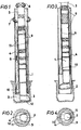
- FIG. 1 shows an embodiment of the device according to the invention, the telescopic connector being in the retracted position, which corresponds to the working position of the hammer.
- Figure 2 is a bottom view of the device of Figure 1.
- Figure 3 shows the device of Figure 1, the telescopic connector being in the developed position, which corresponds to the position of extraction of the drilling member.
- FIG. 4 is a bottom view of the device of FIG. 3.
- the drilling device shown in the figures comprises a hammer 1 fitted with a cutter 2.
- This hammer 1 operates with compressed air which is transmitted to it by elongate tubes 3.
- An external casing 4 maintains the walls of the hole 5.
- the casing is driven in the hole 5 at the same speed of penetration as the drilling member thanks to a thrust controlled by a regulator not shown and to a rotational movement in the opposite direction to the direction of rotation of the drilling member.
- Arrows 6 and 7 show the direction of the rotational movement of the drilling member and of the casing, respectively. 4. It is possible to have either separate motors for the two movements, or a motor with two concentric output shafts rotating in opposite directions. These engines are not shown.
- the casing 4 determines with the drilling member a space through which the exhaust air drives out the drilling sediments, as indicated by arrow 8.
- the outside diameter of the casing 4 is less than the diameter of the drilled hole because the cutter 2 is eccentric.
- This telescopic connector 9 comprises a decentering lug 10 of the hammer-cutter assembly, fixed on a lug holder tube 11 which comes cap the hammer 1.
- This pin holder tube 11 is fixed to the part of the connector 9 which is linked to the elongate tubes 3.
- the telescopic stroke corresponds to a relative rotation of 180 °, so that, when the connector is in the retracted position, which corresponds to the working position of the drilling member ( Figure 1), the eccentric part of the cutter 2 either diametrically opposite the lug 10, and, when the connector is in the developed position, which corresponds to the position of extraction of the drilling member (FIG. 3), the eccentric part of the cutter 2 is placed below lug 10.
- the invention can be applied to more sophisticated drilling devices, for example comprising a fluid injection circuit at the bottom of the hole completely independent of that of the compressed air supply, this fluid having for its purpose to facilitate the rise of sediments.
Landscapes
- Engineering & Computer Science (AREA)
- Life Sciences & Earth Sciences (AREA)
- Geology (AREA)
- Mining & Mineral Resources (AREA)
- Physics & Mathematics (AREA)
- Environmental & Geological Engineering (AREA)
- Fluid Mechanics (AREA)
- General Life Sciences & Earth Sciences (AREA)
- Geochemistry & Mineralogy (AREA)
- Mechanical Engineering (AREA)
- Earth Drilling (AREA)
Applications Claiming Priority (2)
| Application Number | Priority Date | Filing Date | Title |
|---|---|---|---|
| FR7734849A FR2409373A1 (fr) | 1977-11-21 | 1977-11-21 | Dispositif de forage de trous dans le sol, comportant un marteau pneumatique equipe d'un taillant excentre |
| FR7734849 | 1977-11-21 |
Publications (2)
| Publication Number | Publication Date |
|---|---|
| EP0002160A1 EP0002160A1 (fr) | 1979-05-30 |
| EP0002160B1 true EP0002160B1 (fr) | 1980-09-03 |
Family
ID=9197816
Family Applications (1)
| Application Number | Title | Priority Date | Filing Date |
|---|---|---|---|
| EP78400189A Expired EP0002160B1 (fr) | 1977-11-21 | 1978-11-17 | Dispositif de forage de trous dans le sol |
Country Status (9)
| Country | Link |
|---|---|
| US (1) | US4183415A (enExample) |
| EP (1) | EP0002160B1 (enExample) |
| JP (1) | JPS54106001A (enExample) |
| BR (1) | BR7807599A (enExample) |
| CA (1) | CA1098895A (enExample) |
| DE (1) | DE2860155D1 (enExample) |
| ES (1) | ES475233A1 (enExample) |
| FR (1) | FR2409373A1 (enExample) |
| IT (1) | IT1109631B (enExample) |
Families Citing this family (21)
| Publication number | Priority date | Publication date | Assignee | Title |
|---|---|---|---|---|
| DE2924392C2 (de) * | 1979-06-16 | 1982-09-23 | Brückner Grundbau GmbH, 4300 Essen | Bohrvorrichtung zum Überlagerungsbohren |
| DE2924393C2 (de) * | 1979-06-16 | 1983-06-23 | Brückner Grundbau GmbH, 4300 Essen | Bohrvorrichtung zum Überlagerungsbohren |
| DE3024102C2 (de) * | 1980-06-27 | 1982-09-23 | Ing. Günter Klemm, Spezialunternehmen für Bohrtechnik, 5962 Drolshagen | Exzenter-Bohrvorrichtung |
| SE454196C (sv) * | 1983-09-23 | 1991-11-04 | Jan Persson | Jord- och bergborrningsanordning foer samtidig borrning och infodring av borrhaalet |
| FR2596803B1 (fr) * | 1986-04-02 | 1988-06-24 | Elf Aquitaine | Dispositif de forage et cuvelage simultanes |
| SE460300B (sv) * | 1986-10-03 | 1989-09-25 | Loevab Loef Och Oestlund Ab | Roterbart borrverktyg med upprymningsdel till en saenkborrmaskin |
| JPH0617578B2 (ja) * | 1987-05-12 | 1994-03-09 | 株式会社横山基礎工事 | 互層地盤における竪孔掘削工法 |
| US4867255A (en) * | 1988-05-20 | 1989-09-19 | Flowmole Corporation | Technique for steering a downhole hammer |
| JPH089863B2 (ja) * | 1991-08-14 | 1996-01-31 | 株式会社エヌ、アイ、テイ | 全角度地盤改良体造成工法及びその装置 |
| DE4211059C1 (enExample) * | 1992-04-02 | 1993-07-08 | Nikolaus 6624 Grossrosseln De Meier | |
| FI111408B (fi) * | 1998-11-04 | 2003-07-15 | Numa Tool Co | Menetelmä ja laite uppoporauksessa |
| US20110214918A1 (en) * | 2007-08-21 | 2011-09-08 | Keck Joshua N | Excavation Apparatuses and Methods |
| DE102008028997B4 (de) | 2008-06-20 | 2012-03-01 | Dr. Sven Becker und Dr. Michael Bahns GbR (vertretungsberechtigter Gesellschafter: Dr. Sven Becker, 30655 Hannover) | Bohrverfahren und Bohrgerät zur Herstellung eines Bohrlochs in Erde und Gestein |
| IT1391458B1 (it) * | 2008-10-17 | 2011-12-23 | Dalla Gassa Srl | Sistema di perforazione per martello fondo foro a funzionamento eccentrico |
| EP2597249B1 (de) * | 2011-11-24 | 2014-09-10 | Bauer Spezialtiefbau GmbH | Bohrgerät und Verfahren zum Erstellen einer vertikalen Bohrung |
| CN103114807A (zh) * | 2013-01-22 | 2013-05-22 | 中交天津港湾工程研究院有限公司 | 潜孔钻机偏心钻进成孔方法 |
| CA2928134C (en) | 2013-11-22 | 2018-07-31 | Halliburton Energy Services, Inc. | Shock tool for drillstring |
| CN104018781B (zh) * | 2014-06-13 | 2017-02-15 | 武穴市金箭机械有限责任公司 | 一种对称式双偏心块扩孔钻头 |
| EP3336301B1 (de) * | 2016-12-19 | 2023-09-13 | BAUER Maschinen GmbH | Drehbohrwerkzeug und verfahren zum erstellen einer bohrung |
| CN108999601B (zh) * | 2018-07-26 | 2021-04-13 | 中国石油天然气股份有限公司 | 一种化学驱分注井分层流量调配方法 |
| JP7705121B2 (ja) * | 2021-10-05 | 2025-07-09 | 日特建設株式会社 | 二重管削孔装置、及び二重管削孔装置による削孔方法 |
Family Cites Families (12)
| Publication number | Priority date | Publication date | Assignee | Title |
|---|---|---|---|---|
| GB269922A (en) * | 1927-04-22 | 1928-02-09 | Jan Frank | Improvements in bore-hole apparatus |
| US1858926A (en) * | 1928-03-27 | 1932-05-17 | Herbert E Grau | Oil tool device |
| US1996132A (en) * | 1932-05-11 | 1935-04-02 | Clinton L Walker | Deep well drilling and coring system |
| US2754086A (en) * | 1954-10-18 | 1956-07-10 | Kenneth A Summers | Torque and weight control apparatus |
| FR1287554A (fr) * | 1961-02-02 | 1962-03-16 | Procédé et tête foreuse permettant d'élargir, à leur partie inférieure, des forages de diamètre constant pratiqués dans le sol | |
| US3230740A (en) * | 1963-10-16 | 1966-01-25 | Fred K Fox | Drill string shock absorber and vibration dampener |
| BE670646A (enExample) * | 1965-10-07 | |||
| FR1514485A (fr) * | 1967-02-24 | 1968-02-23 | Skanska Cementgjuteriet Ab | Perfectionnement aux foreuses de profondeur à fleurets excentriques |
| CH524755A (de) * | 1969-05-30 | 1972-06-30 | Klemm Bohrtech | Uberlagerungsbohrgerät und Verfahren zu seinem Betrieb |
| SE346354B (enExample) * | 1970-11-27 | 1972-07-03 | Atlas Copco Ab | |
| US3870114A (en) * | 1973-07-23 | 1975-03-11 | Stabilator Ab | Drilling apparatus especially for ground drilling |
| JPS5613433Y2 (enExample) * | 1977-03-07 | 1981-03-28 |
-
1977
- 1977-11-21 FR FR7734849A patent/FR2409373A1/fr active Granted
-
1978
- 1978-11-17 DE DE7878400189T patent/DE2860155D1/de not_active Expired
- 1978-11-17 EP EP78400189A patent/EP0002160B1/fr not_active Expired
- 1978-11-20 BR BR7807599A patent/BR7807599A/pt unknown
- 1978-11-20 US US05/962,792 patent/US4183415A/en not_active Expired - Lifetime
- 1978-11-20 ES ES475233A patent/ES475233A1/es not_active Expired
- 1978-11-21 CA CA316,585A patent/CA1098895A/fr not_active Expired
- 1978-11-21 IT IT69659/78A patent/IT1109631B/it active
- 1978-11-21 JP JP14403078A patent/JPS54106001A/ja active Granted
Also Published As
| Publication number | Publication date |
|---|---|
| IT1109631B (it) | 1985-12-23 |
| JPS54106001A (en) | 1979-08-20 |
| FR2409373A1 (fr) | 1979-06-15 |
| CA1098895A (fr) | 1981-04-07 |
| JPS6151117B2 (enExample) | 1986-11-07 |
| BR7807599A (pt) | 1979-07-24 |
| DE2860155D1 (en) | 1980-12-11 |
| ES475233A1 (es) | 1979-04-01 |
| EP0002160A1 (fr) | 1979-05-30 |
| FR2409373B1 (enExample) | 1982-10-29 |
| US4183415A (en) | 1980-01-15 |
| IT7869659A0 (it) | 1978-11-21 |
Similar Documents
| Publication | Publication Date | Title |
|---|---|---|
| EP0002160B1 (fr) | Dispositif de forage de trous dans le sol | |
| EP0206917B1 (fr) | Dispositif et méthode de protection témporaire d'un outil d'intervention ou d'un instrument de mesure fixé à l'extrémité d'une colonne | |
| FR2767153A1 (fr) | Dispositif et procede de centrage d'un outil dans un conduit notamment dans une tige de forage | |
| CA1116591A (fr) | Appareil de carottage dans le sol | |
| CA2006920C (fr) | Equipement pour garniture de forage comportant un element a actionner, un moteur et des moyens de commande | |
| WO2004001180A1 (fr) | Conduite de guidage telescopique de forage en mer | |
| EP0811724B1 (fr) | Appareil à châssis télescopique pour creuser des tranchées dans le sol | |
| FR2548259A1 (fr) | Carottier remontable par l'interieur des tiges de forage | |
| EP0202151A1 (fr) | Equipement pour train de tiges, tel qu'un train de tiges de forage, comprenant un raccord à fenêtre latérale pour le passage d'un câble | |
| FR2463256A1 (fr) | Outil de forage de fond et procede de forage d'un sondage au moyen de cet outil | |
| EP0212316A1 (fr) | Colonne de forage pour forage à déviations, procédé d'utilisation de cette colonne et dispositif déviateur utilisé dans cette colonne | |
| EP0006036A1 (fr) | Dispositif protecteur, notamment pour tige d'amortisseur télescopique | |
| EP1259792B1 (fr) | Procede et dispositif pour faire penetrer dans le sous-sol marin, en particulier a des profondeurs importantes, un outil tubulaire de prelevements d'echantillons du sol ou de mesure des caracteristiques de ce sol | |
| WO1991009205A1 (fr) | Dispositif et procede de nettoyage d'un puits souterrain | |
| EP0531336B1 (fr) | Carottier double pour forage devie | |
| EP0588373A1 (fr) | Carottier double pour forage dévié | |
| FR2522059A2 (fr) | Methode et dispositif pour effectuer, a l'aide d'outils specialises, des operations telles que des mesures, dans des portions de puits fortement inclinees sur la verticale, ou horizontales | |
| EP0165154B1 (fr) | Méthode et dispositif pour effectuer à l'aide d'outils spécialisés des opérations telles que des mesures, dans des portions de puits fortement inclinées sur la verticale, ou horizontales | |
| EP0166411B1 (fr) | Dispositif et méthode de mesure des efforts transmis par un arbre notamment à un outil de forage | |
| EP1098064A1 (fr) | Dispositif de forage du type à tarière | |
| EP0699803A1 (fr) | Plate-forme pétrolière de forage ou d'exploitation en mer, pourvue de moyens perfectionnés d'ancrage dans le sol marin | |
| FR2873155A1 (fr) | Foreuse hydraulique pour travaux en espace reduit | |
| FR2614332A1 (fr) | Procede pour installer une canalisation souterraine et installation s'y rapportant | |
| EP0299850B1 (fr) | Joint d'étanchéité à soufflet | |
| EP0826835A1 (fr) | Appareil pour creuser dans le sol des tranchées de grande profondeur |
Legal Events
| Date | Code | Title | Description |
|---|---|---|---|
| PUAI | Public reference made under article 153(3) epc to a published international application that has entered the european phase |
Free format text: ORIGINAL CODE: 0009012 |
|
| AK | Designated contracting states |
Designated state(s): BE CH DE GB NL SE |
|
| 17P | Request for examination filed | ||
| GRAA | (expected) grant |
Free format text: ORIGINAL CODE: 0009210 |
|
| AK | Designated contracting states |
Designated state(s): BE CH DE GB NL SE |
|
| REF | Corresponds to: |
Ref document number: 2860155 Country of ref document: DE Date of ref document: 19801211 |
|
| PGFP | Annual fee paid to national office [announced via postgrant information from national office to epo] |
Ref country code: CH Payment date: 19841126 Year of fee payment: 7 |
|
| PGFP | Annual fee paid to national office [announced via postgrant information from national office to epo] |
Ref country code: DE Payment date: 19841127 Year of fee payment: 7 |
|
| PGFP | Annual fee paid to national office [announced via postgrant information from national office to epo] |
Ref country code: SE Payment date: 19841231 Year of fee payment: 7 Ref country code: BE Payment date: 19841231 Year of fee payment: 7 |
|
| PGFP | Annual fee paid to national office [announced via postgrant information from national office to epo] |
Ref country code: NL Payment date: 19861130 Year of fee payment: 9 |
|
| PG25 | Lapsed in a contracting state [announced via postgrant information from national office to epo] |
Ref country code: SE Effective date: 19871118 |
|
| PG25 | Lapsed in a contracting state [announced via postgrant information from national office to epo] |
Ref country code: CH Effective date: 19871130 Ref country code: BE Effective date: 19871130 |
|
| BERE | Be: lapsed |
Owner name: STENUICK FRANCE Effective date: 19871130 |
|
| PG25 | Lapsed in a contracting state [announced via postgrant information from national office to epo] |
Ref country code: NL Effective date: 19880601 |
|
| NLV4 | Nl: lapsed or anulled due to non-payment of the annual fee | ||
| GBPC | Gb: european patent ceased through non-payment of renewal fee | ||
| REG | Reference to a national code |
Ref country code: CH Ref legal event code: PL |
|
| PG25 | Lapsed in a contracting state [announced via postgrant information from national office to epo] |
Ref country code: DE Effective date: 19880802 |
|
| PG25 | Lapsed in a contracting state [announced via postgrant information from national office to epo] |
Ref country code: GB Effective date: 19881117 |
|
| EUG | Se: european patent has lapsed |
Ref document number: 78400189.3 Effective date: 19880912 |
|
| PLBE | No opposition filed within time limit |
Free format text: ORIGINAL CODE: 0009261 |
|
| STAA | Information on the status of an ep patent application or granted ep patent |
Free format text: STATUS: NO OPPOSITION FILED WITHIN TIME LIMIT |