EP0002131B2 - Verbesserter selbstreinigender Extruder - Google Patents
Verbesserter selbstreinigender Extruder Download PDFInfo
- Publication number
- EP0002131B2 EP0002131B2 EP78300632A EP78300632A EP0002131B2 EP 0002131 B2 EP0002131 B2 EP 0002131B2 EP 78300632 A EP78300632 A EP 78300632A EP 78300632 A EP78300632 A EP 78300632A EP 0002131 B2 EP0002131 B2 EP 0002131B2
- Authority
- EP
- European Patent Office
- Prior art keywords
- screw
- screws
- extruder
- cylinder
- flights
- Prior art date
- Legal status (The legal status is an assumption and is not a legal conclusion. Google has not performed a legal analysis and makes no representation as to the accuracy of the status listed.)
- Expired
Links
Images


Classifications
-
- B—PERFORMING OPERATIONS; TRANSPORTING
- B29—WORKING OF PLASTICS; WORKING OF SUBSTANCES IN A PLASTIC STATE IN GENERAL
- B29C—SHAPING OR JOINING OF PLASTICS; SHAPING OF MATERIAL IN A PLASTIC STATE, NOT OTHERWISE PROVIDED FOR; AFTER-TREATMENT OF THE SHAPED PRODUCTS, e.g. REPAIRING
- B29C48/00—Extrusion moulding, i.e. expressing the moulding material through a die or nozzle which imparts the desired form; Apparatus therefor
- B29C48/25—Component parts, details or accessories; Auxiliary operations
- B29C48/36—Means for plasticising or homogenising the moulding material or forcing it through the nozzle or die
- B29C48/50—Details of extruders
- B29C48/505—Screws
- B29C48/64—Screws with two or more threads
- B29C48/65—Screws with two or more threads neighbouring threads or channels having different configurations, e.g. one thread being lower than its neighbouring thread
-
- B—PERFORMING OPERATIONS; TRANSPORTING
- B29—WORKING OF PLASTICS; WORKING OF SUBSTANCES IN A PLASTIC STATE IN GENERAL
- B29B—PREPARATION OR PRETREATMENT OF THE MATERIAL TO BE SHAPED; MAKING GRANULES OR PREFORMS; RECOVERY OF PLASTICS OR OTHER CONSTITUENTS OF WASTE MATERIAL CONTAINING PLASTICS
- B29B7/00—Mixing; Kneading
- B29B7/30—Mixing; Kneading continuous, with mechanical mixing or kneading devices
- B29B7/34—Mixing; Kneading continuous, with mechanical mixing or kneading devices with movable mixing or kneading devices
- B29B7/38—Mixing; Kneading continuous, with mechanical mixing or kneading devices with movable mixing or kneading devices rotary
- B29B7/46—Mixing; Kneading continuous, with mechanical mixing or kneading devices with movable mixing or kneading devices rotary with more than one shaft
- B29B7/48—Mixing; Kneading continuous, with mechanical mixing or kneading devices with movable mixing or kneading devices rotary with more than one shaft with intermeshing devices, e.g. screws
- B29B7/488—Parts, e.g. casings, sealings; Accessories, e.g. flow controlling or throttling devices
- B29B7/489—Screws
-
- B—PERFORMING OPERATIONS; TRANSPORTING
- B29—WORKING OF PLASTICS; WORKING OF SUBSTANCES IN A PLASTIC STATE IN GENERAL
- B29B—PREPARATION OR PRETREATMENT OF THE MATERIAL TO BE SHAPED; MAKING GRANULES OR PREFORMS; RECOVERY OF PLASTICS OR OTHER CONSTITUENTS OF WASTE MATERIAL CONTAINING PLASTICS
- B29B7/00—Mixing; Kneading
- B29B7/80—Component parts, details or accessories; Auxiliary operations
- B29B7/802—Constructions or methods for cleaning the mixing or kneading device
-
- B—PERFORMING OPERATIONS; TRANSPORTING
- B29—WORKING OF PLASTICS; WORKING OF SUBSTANCES IN A PLASTIC STATE IN GENERAL
- B29C—SHAPING OR JOINING OF PLASTICS; SHAPING OF MATERIAL IN A PLASTIC STATE, NOT OTHERWISE PROVIDED FOR; AFTER-TREATMENT OF THE SHAPED PRODUCTS, e.g. REPAIRING
- B29C48/00—Extrusion moulding, i.e. expressing the moulding material through a die or nozzle which imparts the desired form; Apparatus therefor
- B29C48/25—Component parts, details or accessories; Auxiliary operations
- B29C48/251—Design of extruder parts, e.g. by modelling based on mathematical theories or experiments
- B29C48/2517—Design of extruder parts, e.g. by modelling based on mathematical theories or experiments of intermeshing screws
-
- B—PERFORMING OPERATIONS; TRANSPORTING
- B29—WORKING OF PLASTICS; WORKING OF SUBSTANCES IN A PLASTIC STATE IN GENERAL
- B29C—SHAPING OR JOINING OF PLASTICS; SHAPING OF MATERIAL IN A PLASTIC STATE, NOT OTHERWISE PROVIDED FOR; AFTER-TREATMENT OF THE SHAPED PRODUCTS, e.g. REPAIRING
- B29C48/00—Extrusion moulding, i.e. expressing the moulding material through a die or nozzle which imparts the desired form; Apparatus therefor
- B29C48/25—Component parts, details or accessories; Auxiliary operations
- B29C48/27—Cleaning; Purging; Avoiding contamination
- B29C48/2715—Cleaning; Purging; Avoiding contamination of plasticising units
-
- B—PERFORMING OPERATIONS; TRANSPORTING
- B29—WORKING OF PLASTICS; WORKING OF SUBSTANCES IN A PLASTIC STATE IN GENERAL
- B29C—SHAPING OR JOINING OF PLASTICS; SHAPING OF MATERIAL IN A PLASTIC STATE, NOT OTHERWISE PROVIDED FOR; AFTER-TREATMENT OF THE SHAPED PRODUCTS, e.g. REPAIRING
- B29C48/00—Extrusion moulding, i.e. expressing the moulding material through a die or nozzle which imparts the desired form; Apparatus therefor
- B29C48/25—Component parts, details or accessories; Auxiliary operations
- B29C48/36—Means for plasticising or homogenising the moulding material or forcing it through the nozzle or die
- B29C48/395—Means for plasticising or homogenising the moulding material or forcing it through the nozzle or die using screws surrounded by a cooperating barrel, e.g. single screw extruders
- B29C48/40—Means for plasticising or homogenising the moulding material or forcing it through the nozzle or die using screws surrounded by a cooperating barrel, e.g. single screw extruders using two or more parallel screws or at least two parallel non-intermeshing screws, e.g. twin screw extruders
- B29C48/402—Means for plasticising or homogenising the moulding material or forcing it through the nozzle or die using screws surrounded by a cooperating barrel, e.g. single screw extruders using two or more parallel screws or at least two parallel non-intermeshing screws, e.g. twin screw extruders the screws having intermeshing parts
-
- B—PERFORMING OPERATIONS; TRANSPORTING
- B29—WORKING OF PLASTICS; WORKING OF SUBSTANCES IN A PLASTIC STATE IN GENERAL
- B29C—SHAPING OR JOINING OF PLASTICS; SHAPING OF MATERIAL IN A PLASTIC STATE, NOT OTHERWISE PROVIDED FOR; AFTER-TREATMENT OF THE SHAPED PRODUCTS, e.g. REPAIRING
- B29C48/00—Extrusion moulding, i.e. expressing the moulding material through a die or nozzle which imparts the desired form; Apparatus therefor
- B29C48/25—Component parts, details or accessories; Auxiliary operations
- B29C48/36—Means for plasticising or homogenising the moulding material or forcing it through the nozzle or die
- B29C48/395—Means for plasticising or homogenising the moulding material or forcing it through the nozzle or die using screws surrounded by a cooperating barrel, e.g. single screw extruders
- B29C48/40—Means for plasticising or homogenising the moulding material or forcing it through the nozzle or die using screws surrounded by a cooperating barrel, e.g. single screw extruders using two or more parallel screws or at least two parallel non-intermeshing screws, e.g. twin screw extruders
- B29C48/405—Intermeshing co-rotating screws
-
- B—PERFORMING OPERATIONS; TRANSPORTING
- B29—WORKING OF PLASTICS; WORKING OF SUBSTANCES IN A PLASTIC STATE IN GENERAL
- B29C—SHAPING OR JOINING OF PLASTICS; SHAPING OF MATERIAL IN A PLASTIC STATE, NOT OTHERWISE PROVIDED FOR; AFTER-TREATMENT OF THE SHAPED PRODUCTS, e.g. REPAIRING
- B29C48/00—Extrusion moulding, i.e. expressing the moulding material through a die or nozzle which imparts the desired form; Apparatus therefor
- B29C48/25—Component parts, details or accessories; Auxiliary operations
- B29C48/36—Means for plasticising or homogenising the moulding material or forcing it through the nozzle or die
- B29C48/50—Details of extruders
- B29C48/505—Screws
- B29C48/507—Screws characterised by the material or their manufacturing process
-
- B—PERFORMING OPERATIONS; TRANSPORTING
- B29—WORKING OF PLASTICS; WORKING OF SUBSTANCES IN A PLASTIC STATE IN GENERAL
- B29C—SHAPING OR JOINING OF PLASTICS; SHAPING OF MATERIAL IN A PLASTIC STATE, NOT OTHERWISE PROVIDED FOR; AFTER-TREATMENT OF THE SHAPED PRODUCTS, e.g. REPAIRING
- B29C48/00—Extrusion moulding, i.e. expressing the moulding material through a die or nozzle which imparts the desired form; Apparatus therefor
- B29C48/03—Extrusion moulding, i.e. expressing the moulding material through a die or nozzle which imparts the desired form; Apparatus therefor characterised by the shape of the extruded material at extrusion
Definitions
- This invention relates to a novel and improved multi-screw extruder, and more specifically, to a self-cleaning type extruder having multiple screws rotating in the same direction which has been improved so as to achieve uniform and intensive kneading of plastics.
- a self-cleaning type kneading extruder in which the surfaces of multiple intermeshing screws are cleaned by contact with each other or with screw flights.
- Extruders of this type have the function of removing the fluctuations in output, or the rate of stock extrusion, which are caused by blocking of powders in a solid-conveying zone and/or plasticating zone, and of preventing the degradation of the extrudate caused by the sticking or flowing out of the degeneration products in a melt-conveying zone, and have recently attained importance for use in plastica- tion, melting and kneading of polymeric materials and their compositions.
- a "self-cleaning type" extruder has a specified configuration defined by the contour of screws in their cross section at right angles to their axes. It includes at least two screws adapted to rotate in the same direction each of which has one or multiple screw flights, and which are in such a relation that at any position in at least a part of the screws which lies in the longitudinal direction of the extruder, the contour of one screw in a cylinder cross-section taken at right angles to the screw axes is in substantial contact at one point with the contour in the same cross-section of another screw intermeshing therewith.
- Fig. 1 (A) of the attached drawings is a top plan view of the screw section of a typical known self-cleaning type twin-screw extruder (for instance of the type disclosed in U.S. Patent No. 4040607) in which each screw S 1 or S 2 has three flights F 1 , F 2 and F 3 .
- the cross-section of these screws S 1 and S 2 at a certain point in the longitudinal direction, for example, the cross-section taken along the line I-I of Fig. 1(A), is as shown in Fig. 1(B). It is appreciated from this drawing that the contour of the cross-section of screw S 1 is in contact with that of screw S 2 at one point only.
- each screw channel A i , A 2 ,...A 12 or B 1 , B 2 ,....B 9 forms a space substantially completely isolated from the neighboring channels. Accordingly, the stock fed into channel A, of screw S 2 moves necessarily to channel B, of screw S 1 with the rotation of the screws. Then, it moves to channel A 6 of screw 5 2 , further passes channel B 6 of screw S i , and channel A 11 of screw S 2 .
- the stock fed into channel A 2 of screw 5 2 is likewise conveyed through the course A 2 ⁇ B 2 ⁇ A ⁇ B ⁇ A 12 .
- the flowing path of the stock is completely dependent on the screw channel into which the stock has initially been fed.
- the stock which has flowed into the channel A, of screw S 2 follows an "8" figure- patterned helical path A 1 ⁇ B 1 ⁇ A 6 ⁇ B 6 ⁇ A 11 .
- the resin which has flowed into channel A 1 either partly or wholly, never gets together with the stock within the channels A 2 , A3, A4, As, B 2 , 8 3 , 8 4 , and B 5 . In other words, no exchange of stock is performed between channels of one screw and between channels of two intermeshing screws.
- the magnitude of the shearing force of a screw independent from the properties of the stock and the operating conditions is given by the product of the average shear rate (velocity gradient) and the time. Since the time depends upon the various dimensions of the screws in the axial direction, the shear rate at the wall surface will be a representative parameter of the shearing action which is associated with the shape of the extruder in its cross-section at right angles to its axis.
- the shear rate ( ⁇ ⁇ ) at the wall surface is generally proportional to R/H [ ⁇ ⁇ ⁇ R/H].
- R represents the outside diameter of each screw
- H represents the depth of a screw channel.
- the shear rate at the wall surface increases when the distance L between the axes of the screws approaches the outside diameter (R) of the screw flight and thus the depth (H) of the screw channel decreases.
- the volume of the intermeshing part of the screws decreases, and consequently, the time during which the stock undergoes a shearing action decreases. This leads to the reduction of the resin kneading action and the drastic decreases of the output.
- the screw flights of the multiple screws of the aforesaid known self-cleaning type extruder have the same outside diameter (R).
- the conventional self-cleaning type extruders have the serious defect that in order to attain a high shear rate at the wall surface, the kneading action, the resin conveying efficiency, and the rate of extrusion or output must be sacrificed.
- extruder is a biaxial extruder described in DE-A-1802593, and employs a double flight arrangement on each screw with one flight being joined to the other at one side thereof. One of the flights has less radial height that the other.
- this is not a self-cleaning extruder, there being a gap between the screws, and the purpose of the extruder is best obtained when the screws rotate in opposite directions.
- a self-clean type extruder including a cylinder and at least two screws to rotate therein the same rotational direction, the screws being such that at any cross-section along the length of the extruder perpendicular to the screw axes, intermeshing screws are substantially in contact with one another at one point and each screw having at least two spaced apart flights, each flight being separated on both sides from adjacent flight(s) by a channel characterised in that for each screw the top of one flight is substantially in contact with the inner wall of the cylinder and the top of another flight is at a predetermined clearance from the inner wall.
- the extruder of the invention produces a good resin kneading action at the intermeshing parts of the screws and gives a high output (rate of extrusion) while maintaining a high shearing action. It can give uniform and intensive kneading of plastics while retaining the advantages of self-cleaning type extruders, by performing a mutual kneading action based on the exchange of resin between adjacent screw channels in the axial direction of the screws and between screw channels of two intermeshing screws, and attaining a high shearing action betweeen the wall surface of the cylinder and the bottom surface of the screw channels.
- the screws used in the extruder of the invention have at least two screw flights. In theory, any number of flights can be provided, but in practice, the invention prefers screws each having two to four flights.
- the multiple screws incorporated in the extruder of this invention usually have the same outside diameter. But they may have different outside diameters from each other.
- the extruder of this invention has at least two, usually two, such screws.
- FIG 2(A) shows an embodiment of the self-cleaning type extruder of the invention which has two screws 1 and 1' of the same outside diameter each having two screw flights.
- the screws 1 and 1' respectively have flights 3 and 3' whose tops 4 and 4' are in substantial contact with the inner wall surface of a cylinder 2, and flights 5 and 5' whose tops 6 and 6' are spaced from the inner wall surface of the cylinder 2 by a predetermined tip clearance.
- Figure 2(B) which shows the cross-sections of the screws 1 and 1', the cross-sectional shapes of the screws 1 and l' are in a mirror-image relationship to each other.
- the cross-sectional contour of the screw 1 is in substantial contact with that of the screw 1' only at one point.
- the cross-sectional shapes of the screws 1 and 1' are usually designed in such a manner that the contact point p (p') falls on a line connecting crests a and b of the cylinder 2.
- the term "in substantial contact” means that two elements are slidably in frictional contact with each other, or the two elements face each other with such a small gap therebetween that a resin to be kneaded and extruded does not substantially pass through it.
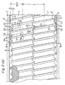
- FIG. 3 Another embodiment of this invention is shown in Figure 3.
- the extruder shown in Figure 3 includes two screws 20 and 20' each of which has three flights 22, 23 and 24, or 22', 23' and 24', respectively.
- Each of tops 27 and 27' of flights 24 and 24' has a tip clearance 6 with respect to the inner wall surface of a cylinder 21, and the remaining tops 25 and 26, or 25' and 26' of the flights 22 and 23 or 22' and 23' are in substantial contact with the inner wall surface of the cylinder 21.
- the tip clearance 6 in the present invention is not strictly limited, and can be varied widely according to the use of the extruder, etc.
- the "outside diameter" of a screw denotes the product obtained by doubling the maximum vertical distance from the top of the screw flight to the central axis of the screw.
- the extruder of the invention is essentially characteristic in the configuration of screws incorporated in it.
- the screws used in this invention should have such a structure that at any position in at least a part of the screws which lies in the longitudinal direction of the extruder, the contour of one screw in a cylinder cross-section taken at right angles to the screw axes is in substantial contact at one point with the contour in the same cross-section of another screw intermeshing therewith.
- Each screw should have at least two screw flights, and the top of at least one of the flights is in substantial contact with the inner wall surface of a cylinder of the extruder, while the top of at least one other screw has a certain tip clearance with respect to the inner wall surface of the cylinder.
- FIGS. 4(A) and (B) The contours of the cross-sections of two intermeshing screws are shown in Figures 4(A) and (B). It is appreciated from these drawings that the contour of a cross-section of a screw taken at right angles to its axis is made up of a combination of a group of arcs AB, CD, EF and GH with the axial core as a center and a group of curves BE, FD, AG and HC determined by a technique of analytical geometry.
- Figure 4(A) shows the contour of one screw in its cross-section taken at right angles to its axis in a phase in which the top of one screw flight agrees with crest b of the cylinder.
- Figure 4(B) shows a similar view in which the top of one screw flight is in a somewhat deviated phase from the crest b of the cylinder.
- the contour 31 of the inner surface of the cylinder is defined by the specific extruder of this invention. As a result, the distance L between the axial cores 0 and 0' of two screws 30 and 30' is determined. From the fact that the top of one screw flight is in substantial contact with the contour 31 of the cylinder, the outside diameter R of the screw can necessarily be determined.
- the angle /_b0'd formed by (1) the straight line c-d forming an angle of 45° with the horizontal axis g-h passing the axial cores 0 and 0' and (2) the straight line b-0' connecting the crest b of the cylinder to the axial core 0' is a'2
- the arc AB can be expressed as an arc having a radius of R/2 with a central angle of a/2 on both sides of straight line 0'-c.
- This arc AB defines the contour of a flight top which makes substantial contact with the inner wall surface of the cylinder.
- the aroEF is an arc having a radius of (L-R/2) with a central angle of a/2 on both sides of straight line e-f which passes the axial core 0' and crosses straight line c-d at right angles thereto. It defines the bottom surface of a screw channel at its deepest position.
- the contour of the top of a flight having a tip clearance ⁇ with respect to the inner wall surface of the cylinder is defined by arc CD.
- the arc CD can be expressed as an arc having a central angle LCO'd when a circle with a radius (R/2- ⁇ ) is drawn about 0' as a center and the intersecting point between the circle and the curve FJ is designated D.
- the arc GH is an arc having a radius of The angle LGO'f equals angle ⁇ C0'd, and angle HO'f equals angle ⁇ D0'd.
- contours of the screws in their cross-section taken at right angles to their axes can be determined in the manner described hereinabove, and this determines the structure of the screws used in this invention.
- a bisecting line c'-d' of the vertical angle A'OB' of a screw flight of screw 30 whose top is in substantial contact with the inner wall surface of the cylinder is drawn, and made a reference line.
- the extruder of the invention described above is designed in such a shape that at least one of the multiple flights of a screw has a tip clearance with respect to the cylinder, it can achieve a unique kneading action in compounding plastics.
- the resin which has moved into the screw channel D 2 is kneaded with the resin present in the screw channel D 1 adjacent thereto via the low screw flight 5 by the interchannel flow in the direction shown by arrow X 2 .
- the extruder of the present invention can achieve an intensive kneading of the resin by the exchanging of resin flows between channels of the same screw and between channels of two intermeshing screws.
- the resin is circulated between adjacent channels through the tip clearance of the flight as shown, for example, by arrows X 1 , X 2 , X 3 and X 4 . Accordingly, the resin undergoes a high shearing action because of the narrow tip clearance. When an unmelted resin or a high viscosity resin is present together in the channels, the tip clearance performs a filter action to make the melt viscosity of the resin highly uniform.
- the extruder of the invention can effect uniform and intensive kneading and mixing of the resin.
Landscapes
- Engineering & Computer Science (AREA)
- Mechanical Engineering (AREA)
- Manufacturing & Machinery (AREA)
- Physics & Mathematics (AREA)
- Algebra (AREA)
- General Physics & Mathematics (AREA)
- Mathematical Analysis (AREA)
- Mathematical Optimization (AREA)
- Mathematical Physics (AREA)
- Pure & Applied Mathematics (AREA)
- Extrusion Moulding Of Plastics Or The Like (AREA)
Claims (3)
Applications Claiming Priority (2)
| Application Number | Priority Date | Filing Date | Title |
|---|---|---|---|
| JP52139248A JPS5829733B2 (ja) | 1977-11-19 | 1977-11-19 | 押出機 |
| JP139248/77 | 1977-11-19 |
Publications (3)
| Publication Number | Publication Date |
|---|---|
| EP0002131A1 EP0002131A1 (de) | 1979-05-30 |
| EP0002131B1 EP0002131B1 (de) | 1982-06-23 |
| EP0002131B2 true EP0002131B2 (de) | 1987-04-22 |
Family
ID=15240889
Family Applications (1)
| Application Number | Title | Priority Date | Filing Date |
|---|---|---|---|
| EP78300632A Expired EP0002131B2 (de) | 1977-11-19 | 1978-11-15 | Verbesserter selbstreinigender Extruder |
Country Status (10)
| Country | Link |
|---|---|
| US (1) | US4300839A (de) |
| EP (1) | EP0002131B2 (de) |
| JP (1) | JPS5829733B2 (de) |
| AU (1) | AU520866B2 (de) |
| CA (1) | CA1124973A (de) |
| DE (1) | DE2861917D1 (de) |
| IT (1) | IT1101116B (de) |
| MX (1) | MX150779A (de) |
| SU (1) | SU1190979A3 (de) |
| WO (1) | WO1979000305A1 (de) |
Families Citing this family (48)
| Publication number | Priority date | Publication date | Assignee | Title |
|---|---|---|---|---|
| DE3038973A1 (de) * | 1980-10-15 | 1982-05-27 | Bayer Ag, 5090 Leverkusen | Verfahren und vorrichtung zum kristallisieren von schmelzen mit gleichzeitiger zerkleinerung |
| JPS59134627U (ja) * | 1983-02-28 | 1984-09-08 | フクビ化学工業株式会社 | 化粧布張り用コ−ナ−部材 |
| DE4239220C2 (de) * | 1992-11-21 | 1996-08-22 | Blach Verfahrenstechnik Gmbh | Gleichdrall - Doppelschneckenextruder |
| IT1279683B1 (it) * | 1995-11-10 | 1997-12-16 | Babbini & C Sas Flli | Pressa disidratante a vite |
| IT1282578B1 (it) * | 1996-02-07 | 1998-03-31 | Pomini Spa | Procedimento e macchina per la mescolazione con laminazione in continuo di materiale termoplastico |
| US6062719A (en) * | 1996-09-24 | 2000-05-16 | The Dow Chemical Company | High efficiency extruder |
| WO1998013189A1 (en) * | 1996-09-24 | 1998-04-02 | The Dow Chemical Company | Multiple-screw extruder |
| JP3499414B2 (ja) * | 1996-12-24 | 2004-02-23 | 株式会社神戸製鋼所 | 2軸混練機 |
| DE19950917A1 (de) * | 1999-10-21 | 2001-04-26 | Degussa | Doppelschneckenextruder mit neuen Schneckenelementen |
| WO2002009919A2 (en) * | 2000-07-31 | 2002-02-07 | Babu Padmanabhan | Fractional and higher lobed co-rotating twin-screw elements |
| DE10114727B4 (de) * | 2001-03-22 | 2005-05-12 | Berstorff Gmbh | Schneckenelement für gleichsinnig drehende Mehrschneckenextruder |
| DE10122462C1 (de) | 2001-05-09 | 2002-10-10 | 3 & Extruder Gmbh | Vorrichtung mit Schnecken zum Homogenisieren und/oder Dispergieren eines viskosen Stoffes und eines Feststoffes und/oder eines anderen Stoffes unterschiedlicher Viskosität |
| DE10143570A1 (de) * | 2001-09-05 | 2003-03-20 | Buehler Ag | Entgasung von fließfähigen Massen in einem Mehrwellenextruder |
| DE10233214B4 (de) * | 2002-07-22 | 2005-01-27 | 3+Extruder Gmbh | Extruder zum kontinuierlichen Bearbeiten und/oder Verarbeiten von fließfähigen Materialien |
| DE10233213B4 (de) | 2002-07-22 | 2004-09-09 | 3+Extruder Gmbh | Extruder |
| DE102004003448B3 (de) * | 2004-01-22 | 2005-11-10 | Nestle S.A. | Tieftemperaturextrusionsverfahren zur Mikrostrukturierung von gefrorenen, belüfteten Massen, beispielsweise Eiskrem, und Tieftemperaturextrusionsvorrichtung zum Durchführen dieses Verfahrens |
| US7390118B2 (en) * | 2004-10-15 | 2008-06-24 | Husky Injection Molding Systems Ltd. | Extruder assembly |
| DE102004052055B4 (de) * | 2004-10-26 | 2014-11-20 | Blach Verwaltung Gmbh & Co.Kg | Extruder |
| DE102005053907B4 (de) * | 2005-11-11 | 2009-05-20 | Blach Verwaltung Gmbh & Co.Kg | Mehrwellenextruder |
| EP1832281A1 (de) | 2006-03-10 | 2007-09-12 | Abbott GmbH & Co. KG | Verfahren zur Herstellung einer Feststoffdispersion eines aktiven Wirkstoffes |
| DE102008016862C5 (de) * | 2008-04-02 | 2019-12-19 | Blach Verwaltungs Gmbh & Co. Kg | Extruder |
| DE102008029305A1 (de) * | 2008-06-20 | 2009-12-24 | Bayer Technology Services Gmbh | Schneckenelemente mit reduziertem Kammwinkel |
| DE102008029306A1 (de) * | 2008-06-20 | 2009-12-24 | Bayer Technology Services Gmbh | Schneckenelemente mit reduziertem Energieeintrag beim Druckaufbau |
| DE102008029304A1 (de) * | 2008-06-20 | 2009-12-24 | Bayer Technology Services Gmbh | Verfahren zur Erzeugung von Schneckenelementen |
| HUE044895T2 (hu) * | 2009-07-16 | 2019-12-30 | Blach Verwaltungs Gmbh & Co Kg | Extruder |
| JP5318709B2 (ja) * | 2009-08-26 | 2013-10-16 | ポリプラスチックス株式会社 | スクリューエレメントピース及びスクリュー |
| DE102009059072A1 (de) * | 2009-12-18 | 2011-06-22 | Bayer Technology Services GmbH, 51373 | Schneckenelemente zur Extrusion viskoelastischer Massen |
| AT509710B1 (de) * | 2010-03-24 | 2011-11-15 | Josef Ing Blach | Extruder |
| CN102259416A (zh) * | 2011-05-31 | 2011-11-30 | 四川金鑫螺杆成套设备有限公司 | 三头螺纹元件及使用该元件的双螺杆挤出机 |
| AT512974B1 (de) * | 2012-05-23 | 2015-02-15 | Josef A Ing Blach | Mehrwellenextruder |
| RU2673517C2 (ru) * | 2013-06-24 | 2018-11-27 | Ковестро Дойчланд Аг | Шнековые элементы для многовальных шнековых машин |
| DE102014219706B3 (de) * | 2014-09-29 | 2016-03-31 | Battenfeld-Cincinnati Austria Gmbh | Extruderschnecke |
| CN104527025B (zh) * | 2014-12-29 | 2017-05-17 | 广东轻工职业技术学院 | 带有折流板的同向自洁双螺杆挤出机及其加工方法 |
| AT519286B1 (de) * | 2016-10-19 | 2018-12-15 | Gruber Dietmar | Doppelschneckenextruder |
| US11752681B2 (en) * | 2017-06-22 | 2023-09-12 | Steer Engineering Private Limited | Method for producing fused unplasticised polyvinyl chloride articles |
| US12370510B2 (en) | 2019-02-27 | 2025-07-29 | Covestro Intellectual Property Gmbh & Co. Kg | Screw element having an axially asymmetrical screw profile which has at least two construction points located within the screw profile |
| FR3093456A1 (fr) | 2019-03-06 | 2020-09-11 | Compagnie Generale Des Etablissements Michelin | Mécanisme de Sortie d’un Mélangeur à Bi-Vis Conique Convergente |
| FR3093458A1 (fr) * | 2019-03-06 | 2020-09-11 | Compagnie Generale Des Etablissements Michelin | Machine de Mélangeage et d’Extrusion à Bi-Vis Autonettoyante et Méthode d’Utilisation |
| FR3093459A1 (fr) | 2019-03-06 | 2020-09-11 | Compagnie Generale Des Etablissements Michelin | Gestion de Température des Mélanges de Caoutchouc Sortant un Mélangeur à Bi-Vis Conique Convergente |
| FR3093457A1 (fr) * | 2019-03-06 | 2020-09-11 | Compagnie Generale Des Etablissements Michelin | Machine de Mélangeage et d’Extrusion à Bi-Vis avec Éléments Amovibles |
| CN111483073A (zh) * | 2020-04-21 | 2020-08-04 | 安徽绿谷新材料有限公司 | 热塑性弹性体加工用双螺杆挤出机及其使用方法 |
| RS66099B1 (sr) * | 2020-06-16 | 2024-11-29 | Michelin & Cie | Linija za proizvodnju gumene smeše koja obuhvata najmanje tri konusne dvopužne mešalice, i povezani postupak |
| EP4164846B1 (de) * | 2020-06-16 | 2024-08-28 | Compagnie Generale Des Etablissements Michelin | Kautschukmischungsherstellungslinie aufweisend zumindest zwei konische doppelschneckenmischer, und zugehöriges verfahren |
| CN113927871B (zh) * | 2021-10-08 | 2022-08-05 | 大连理工大学 | 一种含偏心螺杆的挤出装置及挤出机 |
| EP4489956B1 (de) | 2022-03-11 | 2025-10-22 | Covestro Deutschland AG | Schneckenelemente mit verbesserter mischwirkung und druckaufbau |
| EP4507871A1 (de) | 2022-04-11 | 2025-02-19 | Covestro Deutschland AG | Mehrwellige schneckenmaschine mit einem paar schneckenelementen mit verbesserter misch- und entgasungswirkung bei reduziertem energieeintrag |
| CN115923086B (zh) * | 2022-10-24 | 2025-10-24 | 五邑大学 | 挤出机及挤出加工方法 |
| EP4458548A1 (de) | 2023-05-04 | 2024-11-06 | Covestro Deutschland AG | Schneckenelemente mit verbesserter mischwirkung und verbessertem wärmeübergang und deren verwendung |
Family Cites Families (9)
| Publication number | Priority date | Publication date | Assignee | Title |
|---|---|---|---|---|
| DE14109C (de) * | W. C. BROWN in Sheffield, England | Neuerungen an Vorrichtungen oder Apparaten, um Körper im Wasser schwimmend zu erhalten | ||
| US3104420A (en) * | 1960-12-06 | 1963-09-24 | Gerhard Kestermann K G | Masticator for plastic materials |
| DE1554751B1 (de) * | 1966-09-10 | 1971-01-07 | Kestermann Maschf Rolf | Schnecken-Strangpresse |
| DE1802593B2 (de) * | 1968-10-11 | 1971-12-02 | Doppelschneckenpresse fuer kunststoffe | |
| JPS498936B1 (de) * | 1968-10-21 | 1974-03-01 | ||
| FR2093483A5 (de) * | 1970-05-08 | 1972-01-28 | Plast Elastverarbeitungsmasch | |
| US3900187A (en) * | 1973-10-29 | 1975-08-19 | Baker Perkins Inc | Continuous mixing and/or kneading machine with co-wiping single lead screws |
| DE2446436A1 (de) * | 1974-09-28 | 1976-04-08 | Bayer Ag | Mehrwellige schneckenmaschine |
| US4131371A (en) * | 1977-08-03 | 1978-12-26 | E. I. Du Pont De Nemours And Company | Co-rotating multiple screw processor |
-
1977
- 1977-11-19 JP JP52139248A patent/JPS5829733B2/ja not_active Expired
-
1978
- 1978-11-15 DE DE7878300632T patent/DE2861917D1/de not_active Expired
- 1978-11-15 EP EP78300632A patent/EP0002131B2/de not_active Expired
- 1978-11-16 WO PCT/JP1978/000028 patent/WO1979000305A1/ja not_active Ceased
- 1978-11-17 CA CA316,407A patent/CA1124973A/en not_active Expired
- 1978-11-17 IT IT29902/78A patent/IT1101116B/it active
- 1978-11-17 MX MX175676A patent/MX150779A/es unknown
- 1978-11-20 AU AU41712/78A patent/AU520866B2/en not_active Expired
-
1979
- 1979-06-28 US US06/143,473 patent/US4300839A/en not_active Expired - Lifetime
- 1979-07-17 SU SU792788708A patent/SU1190979A3/ru active
Also Published As
| Publication number | Publication date |
|---|---|
| IT7829902A0 (it) | 1978-11-17 |
| MX150779A (es) | 1984-07-16 |
| WO1979000305A1 (fr) | 1979-05-31 |
| EP0002131B1 (de) | 1982-06-23 |
| JPS5829733B2 (ja) | 1983-06-24 |
| IT1101116B (it) | 1985-09-28 |
| US4300839A (en) | 1981-11-17 |
| CA1124973A (en) | 1982-06-08 |
| EP0002131A1 (de) | 1979-05-30 |
| DE2861917D1 (en) | 1982-08-12 |
| JPS5472265A (en) | 1979-06-09 |
| SU1190979A3 (ru) | 1985-11-07 |
| AU520866B2 (en) | 1982-03-04 |
| AU4171278A (en) | 1979-05-24 |
Similar Documents
| Publication | Publication Date | Title |
|---|---|---|
| EP0002131B2 (de) | Verbesserter selbstreinigender Extruder | |
| US5000900A (en) | Twin screw extruder | |
| US5932159A (en) | Screw extruder with improved dispersive mixing | |
| US6042260A (en) | Method of carrying out continuous preparation processes on tightly meshing extruders rotating in the same sense | |
| US5215764A (en) | Extruder mixing screw | |
| US5244373A (en) | Extruder for poorly miscible extrudates | |
| US6062719A (en) | High efficiency extruder | |
| KR101086079B1 (ko) | 혼련 디스크 세그먼트 및 트윈-스크류 압출기 | |
| PL182591B1 (pl) | Wyrób z tworzywa sztucznego, sposób wykonywania wyrobu z tworzywa sztucznego i urządzenie do wykonywania wyrobu z tworzywa sztucznego | |
| JPS60202723A (ja) | 連続式混合およびせん断ロ−ルミル | |
| US3680844A (en) | Single worm extruder | |
| US6022133A (en) | Multiple-screw extruder | |
| EP1768823B1 (de) | Vorrichtung zum plastifizieren von polypropylen enthaltendem thermoplastischem harz | |
| DE19950917A1 (de) | Doppelschneckenextruder mit neuen Schneckenelementen | |
| CA2057603C (en) | Extruder for poorly miscible extrudates | |
| JP4484366B2 (ja) | 同時回転する双軸押し出し機 | |
| JP3659685B2 (ja) | 熱可塑性樹脂混練押出機 | |
| EP4232259B1 (de) | Extruder mit besonderer anordnung von asymmetrischen schneckenelementen auf schneckenwellen | |
| JPH07148821A (ja) | スクリュータイプの押し出し機用のスクリュー要素及び当該スクリュー要素を有するスクリューシャフト配置 | |
| KR0140270B1 (ko) | 단축압출기용 카오스 스크류(Chaos Screw) | |
| CN216732939U (zh) | 一种高效聚乙烯管材挤出机专用螺杆 | |
| CN213972492U (zh) | 一种用于双螺杆挤出机的啮合盘元件 | |
| JPH0215632Y2 (de) | ||
| JPS6017304Y2 (ja) | 単軸押出機スクリュ− | |
| JPH03126519A (ja) | 直列二段押出機 |
Legal Events
| Date | Code | Title | Description |
|---|---|---|---|
| PUAI | Public reference made under article 153(3) epc to a published international application that has entered the european phase |
Free format text: ORIGINAL CODE: 0009012 |
|
| AK | Designated contracting states |
Designated state(s): CH DE FR GB NL |
|
| 17P | Request for examination filed | ||
| DET | De: translation of patent claims | ||
| GRAA | (expected) grant |
Free format text: ORIGINAL CODE: 0009210 |
|
| AK | Designated contracting states |
Designated state(s): CH DE FR GB NL |
|
| REF | Corresponds to: |
Ref document number: 2861917 Country of ref document: DE Date of ref document: 19820812 |
|
| PGFP | Annual fee paid to national office [announced via postgrant information from national office to epo] |
Ref country code: SE Payment date: 19821231 Year of fee payment: 5 |
|
| PLBI | Opposition filed |
Free format text: ORIGINAL CODE: 0009260 |
|
| 26 | Opposition filed |
Opponent name: WERNER & PFLEIDERER Effective date: 19830322 |
|
| PUAH | Patent maintained in amended form |
Free format text: ORIGINAL CODE: 0009272 |
|
| STAA | Information on the status of an ep patent application or granted ep patent |
Free format text: STATUS: PATENT MAINTAINED AS AMENDED |
|
| 27A | Patent maintained in amended form |
Effective date: 19870422 |
|
| AK | Designated contracting states |
Kind code of ref document: B2 Designated state(s): CH DE FR GB NL |
|
| ET3 | Fr: translation filed ** decision concerning opposition | ||
| NLR2 | Nl: decision of opposition | ||
| NLR3 | Nl: receipt of modified translations in the netherlands language after an opposition procedure | ||
| PGFP | Annual fee paid to national office [announced via postgrant information from national office to epo] |
Ref country code: GB Payment date: 19901105 Year of fee payment: 13 |
|
| PGFP | Annual fee paid to national office [announced via postgrant information from national office to epo] |
Ref country code: FR Payment date: 19901114 Year of fee payment: 13 |
|
| PGFP | Annual fee paid to national office [announced via postgrant information from national office to epo] |
Ref country code: NL Payment date: 19901130 Year of fee payment: 13 |
|
| PGFP | Annual fee paid to national office [announced via postgrant information from national office to epo] |
Ref country code: CH Payment date: 19901203 Year of fee payment: 13 |
|
| PG25 | Lapsed in a contracting state [announced via postgrant information from national office to epo] |
Ref country code: GB Effective date: 19911115 |
|
| PG25 | Lapsed in a contracting state [announced via postgrant information from national office to epo] |
Ref country code: CH Effective date: 19911130 |
|
| PG25 | Lapsed in a contracting state [announced via postgrant information from national office to epo] |
Ref country code: NL Effective date: 19920601 |
|
| GBPC | Gb: european patent ceased through non-payment of renewal fee | ||
| NLV4 | Nl: lapsed or anulled due to non-payment of the annual fee | ||
| PG25 | Lapsed in a contracting state [announced via postgrant information from national office to epo] |
Ref country code: FR Effective date: 19920731 |
|
| REG | Reference to a national code |
Ref country code: CH Ref legal event code: PL |
|
| REG | Reference to a national code |
Ref country code: FR Ref legal event code: ST |
|
| PGFP | Annual fee paid to national office [announced via postgrant information from national office to epo] |
Ref country code: DE Payment date: 19961122 Year of fee payment: 19 |
|
| PG25 | Lapsed in a contracting state [announced via postgrant information from national office to epo] |
Ref country code: DE Free format text: LAPSE BECAUSE OF NON-PAYMENT OF DUE FEES Effective date: 19980801 |