DE69737377T2 - Control valve and liquid supply / drainage system - Google Patents
Control valve and liquid supply / drainage system Download PDFInfo
- Publication number
- DE69737377T2 DE69737377T2 DE1997637377 DE69737377T DE69737377T2 DE 69737377 T2 DE69737377 T2 DE 69737377T2 DE 1997637377 DE1997637377 DE 1997637377 DE 69737377 T DE69737377 T DE 69737377T DE 69737377 T2 DE69737377 T2 DE 69737377T2
- Authority
- DE
- Germany
- Prior art keywords
- valve
- coil
- fluid
- control valve
- fluid control
- Prior art date
- Legal status (The legal status is an assumption and is not a legal conclusion. Google has not performed a legal analysis and makes no representation as to the accuracy of the status listed.)
- Expired - Lifetime
Links
- 239000007788 liquid Substances 0.000 title 1
- 239000012530 fluid Substances 0.000 claims abstract description 151
- 230000005674 electromagnetic induction Effects 0.000 claims abstract description 8
- 230000005284 excitation Effects 0.000 claims description 12
- 239000000696 magnetic material Substances 0.000 abstract description 28
- 238000003825 pressing Methods 0.000 abstract description 3
- 239000007789 gas Substances 0.000 description 53
- 230000004907 flux Effects 0.000 description 32
- 210000004379 membrane Anatomy 0.000 description 25
- 230000035484 reaction time Effects 0.000 description 24
- 239000012528 membrane Substances 0.000 description 23
- XEEYBQQBJWHFJM-UHFFFAOYSA-N Iron Chemical group [Fe] XEEYBQQBJWHFJM-UHFFFAOYSA-N 0.000 description 17
- 239000000956 alloy Substances 0.000 description 12
- 229910045601 alloy Inorganic materials 0.000 description 12
- 230000007246 mechanism Effects 0.000 description 9
- 238000004891 communication Methods 0.000 description 8
- 238000000034 method Methods 0.000 description 8
- 230000000694 effects Effects 0.000 description 7
- 229910052742 iron Inorganic materials 0.000 description 7
- 229920005989 resin Polymers 0.000 description 7
- 239000011347 resin Substances 0.000 description 7
- PXHVJJICTQNCMI-UHFFFAOYSA-N Nickel Chemical compound [Ni] PXHVJJICTQNCMI-UHFFFAOYSA-N 0.000 description 6
- 230000008859 change Effects 0.000 description 6
- 230000005684 electric field Effects 0.000 description 6
- 239000000463 material Substances 0.000 description 6
- 238000010586 diagram Methods 0.000 description 4
- 230000033001 locomotion Effects 0.000 description 4
- 239000011553 magnetic fluid Substances 0.000 description 4
- 238000004519 manufacturing process Methods 0.000 description 4
- 230000035939 shock Effects 0.000 description 4
- 239000010941 cobalt Substances 0.000 description 3
- 229910017052 cobalt Inorganic materials 0.000 description 3
- GUTLYIVDDKVIGB-UHFFFAOYSA-N cobalt atom Chemical compound [Co] GUTLYIVDDKVIGB-UHFFFAOYSA-N 0.000 description 3
- 238000007599 discharging Methods 0.000 description 3
- 239000000203 mixture Substances 0.000 description 3
- 229910052759 nickel Inorganic materials 0.000 description 3
- 239000004065 semiconductor Substances 0.000 description 3
- 229910052720 vanadium Inorganic materials 0.000 description 3
- LEONUFNNVUYDNQ-UHFFFAOYSA-N vanadium atom Chemical compound [V] LEONUFNNVUYDNQ-UHFFFAOYSA-N 0.000 description 3
- IJGRMHOSHXDMSA-UHFFFAOYSA-N Atomic nitrogen Chemical compound N#N IJGRMHOSHXDMSA-UHFFFAOYSA-N 0.000 description 2
- QVYYOKWPCQYKEY-UHFFFAOYSA-N [Fe].[Co] Chemical compound [Fe].[Co] QVYYOKWPCQYKEY-UHFFFAOYSA-N 0.000 description 2
- 230000004913 activation Effects 0.000 description 2
- 230000033228 biological regulation Effects 0.000 description 2
- 238000006243 chemical reaction Methods 0.000 description 2
- 230000007797 corrosion Effects 0.000 description 2
- 238000005260 corrosion Methods 0.000 description 2
- 238000013461 design Methods 0.000 description 2
- 230000005611 electricity Effects 0.000 description 2
- 230000005672 electromagnetic field Effects 0.000 description 2
- 230000006870 function Effects 0.000 description 2
- 230000000977 initiatory effect Effects 0.000 description 2
- 238000009434 installation Methods 0.000 description 2
- 238000005259 measurement Methods 0.000 description 2
- 238000006386 neutralization reaction Methods 0.000 description 2
- 238000013021 overheating Methods 0.000 description 2
- 230000035699 permeability Effects 0.000 description 2
- 238000010926 purge Methods 0.000 description 2
- 230000009467 reduction Effects 0.000 description 2
- 230000001105 regulatory effect Effects 0.000 description 2
- 230000004044 response Effects 0.000 description 2
- 229920006395 saturated elastomer Polymers 0.000 description 2
- 238000003860 storage Methods 0.000 description 2
- BFKJFAAPBSQJPD-UHFFFAOYSA-N tetrafluoroethene Chemical group FC(F)=C(F)F BFKJFAAPBSQJPD-UHFFFAOYSA-N 0.000 description 2
- MIZLGWKEZAPEFJ-UHFFFAOYSA-N 1,1,2-trifluoroethene Chemical group FC=C(F)F MIZLGWKEZAPEFJ-UHFFFAOYSA-N 0.000 description 1
- 241001136792 Alle Species 0.000 description 1
- 101100453960 Drosophila melanogaster klar gene Proteins 0.000 description 1
- 229910017061 Fe Co Inorganic materials 0.000 description 1
- KRHYYFGTRYWZRS-UHFFFAOYSA-M Fluoride anion Chemical compound [F-] KRHYYFGTRYWZRS-UHFFFAOYSA-M 0.000 description 1
- 229910001030 Iron–nickel alloy Inorganic materials 0.000 description 1
- WGLPBDUCMAPZCE-UHFFFAOYSA-N Trioxochromium Chemical compound O=[Cr](=O)=O WGLPBDUCMAPZCE-UHFFFAOYSA-N 0.000 description 1
- 208000012886 Vertigo Diseases 0.000 description 1
- 230000009471 action Effects 0.000 description 1
- 230000009286 beneficial effect Effects 0.000 description 1
- 230000002146 bilateral effect Effects 0.000 description 1
- 230000003197 catalytic effect Effects 0.000 description 1
- 229910000423 chromium oxide Inorganic materials 0.000 description 1
- 238000002485 combustion reaction Methods 0.000 description 1
- 238000010276 construction Methods 0.000 description 1
- 238000005520 cutting process Methods 0.000 description 1
- 238000013016 damping Methods 0.000 description 1
- 238000001514 detection method Methods 0.000 description 1
- 238000011038 discontinuous diafiltration by volume reduction Methods 0.000 description 1
- 238000006073 displacement reaction Methods 0.000 description 1
- 238000005516 engineering process Methods 0.000 description 1
- 210000003746 feather Anatomy 0.000 description 1
- 150000002222 fluorine compounds Chemical class 0.000 description 1
- 238000011835 investigation Methods 0.000 description 1
- UGKDIUIOSMUOAW-UHFFFAOYSA-N iron nickel Chemical compound [Fe].[Ni] UGKDIUIOSMUOAW-UHFFFAOYSA-N 0.000 description 1
- 230000014759 maintenance of location Effects 0.000 description 1
- 229910052757 nitrogen Inorganic materials 0.000 description 1
- 238000003199 nucleic acid amplification method Methods 0.000 description 1
- 108090000623 proteins and genes Proteins 0.000 description 1
- 230000003252 repetitive effect Effects 0.000 description 1
- 229920002050 silicone resin Polymers 0.000 description 1
- 210000002023 somite Anatomy 0.000 description 1
- XLYOFNOQVPJJNP-UHFFFAOYSA-N water Substances O XLYOFNOQVPJJNP-UHFFFAOYSA-N 0.000 description 1
Classifications
-
- F—MECHANICAL ENGINEERING; LIGHTING; HEATING; WEAPONS; BLASTING
- F16—ENGINEERING ELEMENTS AND UNITS; GENERAL MEASURES FOR PRODUCING AND MAINTAINING EFFECTIVE FUNCTIONING OF MACHINES OR INSTALLATIONS; THERMAL INSULATION IN GENERAL
- F16K—VALVES; TAPS; COCKS; ACTUATING-FLOATS; DEVICES FOR VENTING OR AERATING
- F16K31/00—Actuating devices; Operating means; Releasing devices
- F16K31/02—Actuating devices; Operating means; Releasing devices electric; magnetic
- F16K31/06—Actuating devices; Operating means; Releasing devices electric; magnetic using a magnet, e.g. diaphragm valves, cutting off by means of a liquid
- F16K31/08—Actuating devices; Operating means; Releasing devices electric; magnetic using a magnet, e.g. diaphragm valves, cutting off by means of a liquid using a permanent magnet
- F16K31/082—Actuating devices; Operating means; Releasing devices electric; magnetic using a magnet, e.g. diaphragm valves, cutting off by means of a liquid using a permanent magnet using a electromagnet and a permanent magnet
-
- F—MECHANICAL ENGINEERING; LIGHTING; HEATING; WEAPONS; BLASTING
- F16—ENGINEERING ELEMENTS AND UNITS; GENERAL MEASURES FOR PRODUCING AND MAINTAINING EFFECTIVE FUNCTIONING OF MACHINES OR INSTALLATIONS; THERMAL INSULATION IN GENERAL
- F16K—VALVES; TAPS; COCKS; ACTUATING-FLOATS; DEVICES FOR VENTING OR AERATING
- F16K31/00—Actuating devices; Operating means; Releasing devices
- F16K31/02—Actuating devices; Operating means; Releasing devices electric; magnetic
- F16K31/06—Actuating devices; Operating means; Releasing devices electric; magnetic using a magnet, e.g. diaphragm valves, cutting off by means of a liquid
- F16K31/0644—One-way valve
- F16K31/0655—Lift valves
-
- F—MECHANICAL ENGINEERING; LIGHTING; HEATING; WEAPONS; BLASTING
- F16—ENGINEERING ELEMENTS AND UNITS; GENERAL MEASURES FOR PRODUCING AND MAINTAINING EFFECTIVE FUNCTIONING OF MACHINES OR INSTALLATIONS; THERMAL INSULATION IN GENERAL
- F16K—VALVES; TAPS; COCKS; ACTUATING-FLOATS; DEVICES FOR VENTING OR AERATING
- F16K31/00—Actuating devices; Operating means; Releasing devices
- F16K31/02—Actuating devices; Operating means; Releasing devices electric; magnetic
- F16K31/06—Actuating devices; Operating means; Releasing devices electric; magnetic using a magnet, e.g. diaphragm valves, cutting off by means of a liquid
- F16K31/0644—One-way valve
- F16K31/0672—One-way valve the valve member being a diaphragm
-
- F—MECHANICAL ENGINEERING; LIGHTING; HEATING; WEAPONS; BLASTING
- F16—ENGINEERING ELEMENTS AND UNITS; GENERAL MEASURES FOR PRODUCING AND MAINTAINING EFFECTIVE FUNCTIONING OF MACHINES OR INSTALLATIONS; THERMAL INSULATION IN GENERAL
- F16K—VALVES; TAPS; COCKS; ACTUATING-FLOATS; DEVICES FOR VENTING OR AERATING
- F16K7/00—Diaphragm valves or cut-off apparatus, e.g. with a member deformed, but not moved bodily, to close the passage ; Pinch valves
- F16K7/12—Diaphragm valves or cut-off apparatus, e.g. with a member deformed, but not moved bodily, to close the passage ; Pinch valves with flat, dished, or bowl-shaped diaphragm
- F16K7/14—Diaphragm valves or cut-off apparatus, e.g. with a member deformed, but not moved bodily, to close the passage ; Pinch valves with flat, dished, or bowl-shaped diaphragm arranged to be deformed against a flat seat
-
- Y—GENERAL TAGGING OF NEW TECHNOLOGICAL DEVELOPMENTS; GENERAL TAGGING OF CROSS-SECTIONAL TECHNOLOGIES SPANNING OVER SEVERAL SECTIONS OF THE IPC; TECHNICAL SUBJECTS COVERED BY FORMER USPC CROSS-REFERENCE ART COLLECTIONS [XRACs] AND DIGESTS
- Y10—TECHNICAL SUBJECTS COVERED BY FORMER USPC
- Y10T—TECHNICAL SUBJECTS COVERED BY FORMER US CLASSIFICATION
- Y10T137/00—Fluid handling
- Y10T137/8158—With indicator, register, recorder, alarm or inspection means
- Y10T137/8225—Position or extent of motion indicator
- Y10T137/8242—Electrical
Abstract
Description
Technologisches Gebiettechnological area
Die vorliegende Erfindung bezieht sich auf ein Regelventil für ein Fluid und ein Zufuhr-/Auslasssystem für Fluid. Im größeren Detail betrifft die vorliegende Erfindung ein Regelventil für ein Fluid und ein Zufuhr-/Auslasssystem für Fluid, in welchem ein Element, welches einstückig mit einem stangenförmigen Schaft ausgeführt ist, der einen Druck auf einen Ventilhalter aufbringt, durch eine Spule nach oben und nach unten bewegt wird, wobei elektromagnetische Induktion verwendet wird, und dadurch der Bereich zwischen dem Ventilsitz und dem Ventilhalter geöffnet und geschlossen wird. Das Regelventil für Fluid und das Zufuhr-/Auslasssystem für Fluid der vorliegenden Erfindung wird hauptsächlich in Vorrichtungen zur Halbleiterherstellung verwendet.The The present invention relates to a control valve for a fluid and a supply / exhaust system for Fluid. In greater detail The present invention relates to a control valve for a fluid and a supply / exhaust system for Fluid, in which an element which is integral with a rod-shaped shaft accomplished , which applies a pressure on a valve holder, by a Coil is moved up and down, being electromagnetic Induction is used, and thereby the area between the valve seat and opened the valve holder and closed. The fluid control valve and fluid delivery / exhaust system The present invention is mainly used in devices for Semiconductor manufacturing used.
Stand der TechnikState of technology
Herkömmlich wiesen Regelventile für ein Fluid, welche Fluide, die durch den Ventilrumpf strömen, mittels des Öffnens und Schließens eines Bereichs zwischen einem Ventilsitz und einem Ventilhalter, wobei eine Antriebseinheit verwendet wird, regelten, Ventilhalter, umfassend eine Membran, und einen Membranhalter auf, und entsprachen den nachfolgenden Typen.
- (1) Einem Typ, welcher eine Drehmechanismuseinheit aufweist, die manuell betätigt wird, in welchem eine Ventilstange nach oben und nach unten bewegt wird, wobei die Drehbewegung der Drehmechanismuseinheit verwendet wird, und der Bereich zwischen dem Ventilsitz und der Membran geöffnet und geschlossen wird (nachfolgend wird dieser Typ eines Regelventils für ein Fluid als ein manuelles Ventil bezeichnet: nicht in den Figuren gezeigt).
- (2) Einem Typ, welcher einen Gasfüllungs- und Entladungsmechanismus
aufweist, in welchem die Ventilstange nach oben und nach unten bewegt
wird, wobei eine Differenz in dem Druck in diesem Gas verwendet
wird, und der Bereich zwischen dem Ventilsitz und der Membran geöffnet und
geschlossen wird (nachfolgend wird dieser Typ des Regelventils für ein Fluid
als ein Luftdruckventil bezeichnet:
4 ). - (3) Einem Typ, welcher einen Mechanismus aufweist, der einer
elektromagnetischen Induktion ausgesetzt ist, wobei eine Spule verwendet
wird, in welchem ein Eisenkern und ein Kolben an getrennten Positionen installiert
sind, wobei dieser Mechanismus verwendet wird, und zusammen mit
diesem eine Blasenscheibe (Bubble Disc), die an einem Kolben befestigt
ist, nach oben und nach unten bewegt wird, und ein Bereich zwischen
der Blasenscheibe und einem Ventilsitz geöffnet und geschlossen wird
(nachfolgend wird dieser Typ des Regelventils für ein Fluid als ein elektromagnetisches
Ventil bezeichnet:
5 ). Ein Beispiel eines solchen Ventils ist inEP 0 701 053 A2
- (1) A type having a rotary mechanism unit that is manually operated in which a valve rod is moved up and down using the rotary motion of the rotary mechanism unit, and the area between the valve seat and the diaphragm is opened and closed (FIG. hereinafter, this type of fluid control valve will be referred to as a manual valve: not shown in the figures).
- (2) A type having a gas filling and discharging mechanism in which the valve rod is moved up and down using a difference in pressure in this gas, and the area between the valve seat and the diaphragm is opened and closed (hereinafter, this type of control valve for a fluid will be referred to as an air pressure valve:
4 ). - (3) A type having a mechanism subjected to electromagnetic induction using a coil in which an iron core and a piston are installed at separate positions using this mechanism, and together with this, a bubble plate (FIG. Bubble Disc), which is attached to a piston, is moved up and down, and an area between the bubble disc and a valve seat is opened and closed (hereinafter, this type of control valve for a fluid is referred to as an electromagnetic valve:
5 ). An example of such a valve is inEP 0 701 053 A2
Nachfolgend wird das Verfahren des Öffnens und Schließens des Ventils in elektromagnetischen Ventilen und Luftdruckventilen, welche als automatische Ventile bezeichnet werden, erklärt werden.following becomes the method of opening and closing the valve in electromagnetic valves and air pressure valves, which are referred to as automatic valves can be explained.
Die
(Betätigung geschlossen -> geöffnet)(Operation closed -> opened)
Als
ein Ergebnis des Füllens
einer Instrumentierungsgaseinlassöffnung
(Betätigung offen -> geschlossen)(Activation open -> closed)
Als
ein Ergebnis des Beendens des Befüllens der Instrumentierungsgaseinlassöffnung
Die
(Betätigung geschlossen -> offen)(Operation closed -> open)
Als
ein Ergebnis des Eingebens von Elektrizität ausgehend von dem Anschluss
(Betätigung offen -> geschlossen) (Activation open -> closed)
Durch
Abschneiden des Stromflusses zu der Spule
Eine
Ventilbaugruppe, welche einen Ventilsitz aufweist und mit einem
Ventilelement betätigbar
ist, wird durch die
Die vorliegenden Erfinder haben jedoch festgestellt, dass diese Ventile den nachfolgenden Problemen im Hinblick auf die Reaktionszeit (das Ausmaß von Zeit, welches aus dem Zustand, in welchem das Ventil geschlossen war, zu demjenigen, in welchem es geöffnet ist, erforderlich ist) unterliegen.
- (1) In dem Fall des manuell betätigten Ventils ist die Zeit, welche erforderlich ist, um den Handgriff zu drehen, die Reaktionszeit, so dass Unterschiede hergestellt werden, in Abhängigkeit des individuellen Bedieners, und es ist extrem schwierig, die Öffnungs- und Schließungsbetätigung des Ventils in weniger als zum Beispiel 100 ms (Millisekunden) stabil herbeizuführen, und weil die Anzahl der Ventile, welche betätigt werden müssen, zunimmt, ist es nicht bloß so, dass die notwendige Zeit zunimmt, sondern es ist ebenso möglich, dass Fehler in der Reihenfolge der Betätigung gemacht werden und eine Rückströmung und ähnliches verursacht wird.
- (2) Das Luftdruckventil, welches auch als automatisches Ventil bezeichnet wird, weist eine Struktur auf, die hochgradig luftdicht ist, und kann solange leicht gesteuert werden, solange der Fluiddruck 10 kg/cm2 oder weniger beträgt. Die Zeit, welche zum Laden und Entladen des Gases in die Antriebseinheit in diesem Luftdruckventil jedoch erforderlich ist belegt näherungsweise 90 Prozent der Reaktionszeit, so dass die Öffnungs- und Schließungsbetätigung des Ventils langsam ist, bei einigen Zehnten von Millisekunden liegt, und als ein Ergebnis der Länge der Instrumentierungsröhre, welche das Gas zuführt, oder des Druckes, mit welchem das Gas zugeführt wird, kann die Reaktionszeit der Ventile variieren. Als ein Ergebnis werden Unregelmäßigkeiten in der Betätigungsreihenfolge der Ventile und der tatsächlichen Betätigungsreihenfolge produziert, und es gibt Fälle, in welchen eine Rückströmung produziert wird.
- (3) Als ein Verfahren des Eliminierens der Probleme in (2) oben ist ein Verfahren angewendet worden, in welchem die Länge von jeder Instrumentierungsröhre und der Gasdruck innerhalb jeder Instrumentierungsröhre auf denselben Wert gesetzt worden ist.
- (1) In the case of the manually operated valve, the time required to rotate the handle is the reaction time so that differences are made depending on the individual operator, and it is extremely difficult to perform the opening and closing operation of the valve in less than 100 ms (milliseconds), for example, and because the number of valves which must be actuated increases, not only is the necessary time increasing, but it is also possible that errors in the order of actuation are made and a backflow and the like is caused.
- (2) The air pressure valve, which is also called an automatic valve, has a structure which is highly airtight, and can be easily controlled as long as the fluid pressure is 10 kg / cm 2 or less. However, the time required to charge and discharge the gas into the propulsion unit in this air pressure valve occupies approximately 90 percent of the reaction time, so that the opening and closing operation of the valve is slow, at a few tenths of milliseconds, and as a result Length of the instrumentation tube supplying the gas or the pressure with which the gas is supplied may vary the reaction time of the valves. As a result, irregularities in the operation order of the valves and the actual operation order are produced, and there are cases in which backflow is produced.
- (3) As a method of eliminating the problems in (2) above, a method has been adopted in which the length of each instrumentation tube and the gas pressure within each instrumentation tube have been set to the same value.
Zum Beispiel bei Strömungsregeleinrichtungen für Vorrichtungen zur Herstellung von Halbleitern und ähnlichem werden jedoch in solchen Vorrichtungen, welche eine große Anzahl von Regelventilen für Fluid verwenden, elektromagnetische Ventile und ähnliches angewendet, um Gas in den Antriebseinheiten der Luftdruckventile zu laden und zu entladen; weil jedoch die Abstände zwischen den elektromagnetischen Ventilen und den Luftdruckventilen für jede Instrumentierungsröhre variieren, ist es notwendig, die Längen von allen Instrumentierungsröhren entsprechend dem Regelventil für Fluid, welches auf dem größten Abstand liegt, anzuordnen. Aus diesem Grund ist ein Lagerraum in den Fluidregelventilen notwendig, welche sich nahe dem elektromagnetischen Ventil befinden, für unnötige Instrumentierungsröhren, und im Hinblick auf die Gesamtheit der Fluidregeleinrichtung ist es zudem nur möglich, ein System aufzubauen, in welchem die Geschwindigkeit durch das Fluidregelventil bestimmt wird, welches die längste Reaktionsdauer aufweist.
- (4) Wie oben beschrieben worden ist, werden elektromagnetische Ventile vorzugsweise bei dem Laden und Entladen von Gas in den Antriebseinheiten der Luftdruckventile verwendet. Insbesondere können diese Ventile, wie leicht aus dem Aufbau verstanden werden kann, innerhalb von wenigen Millisekunden schnell geöffnet und geschlossen werden. Wie jedoch klar aus dieser Verwendung ist, ist die Struktur derart, dass sie eine Gasleckage zulässt, und zudem gibt es ein großes Ausmaß von Totraum innerhalb der Ventile. Aus diesem Grund sind solche Ventile nicht für Anwendungen, wie zum Beispiel die genaue Steuerung der speziellen Gase bei den Verfahren zur Halbleiterherstellung geeignet.
- (4) As described above, electromagnetic valves are preferably used in the charging and discharging of gas in the drive units of the air pressure valves. In particular, these can Valves, as can be easily understood from the structure, quickly opened and closed within a few milliseconds. However, as is clear from this use, the structure is such as to allow for gas leakage and, in addition, there is a large amount of dead space within the valves. For this reason, such valves are not suitable for applications such as the precise control of specific gases in semiconductor manufacturing processes.
Die vorliegende Erfindung weist als eine ihrer Aufgaben auf, ein Regelventil für Fluid darzustellen, und ein Zufuhr-/Entladesystem für Fluid, in welchem Fluid stabil bei einem Druck von näherungsweise 10 kg/cm2 geregelt werden kann, die Ventile schnell sind, eine Reaktionszeit von wenigen Millisekunden aufweisen, und die Miniaturisierung des Ventils, und weil ein Instrumentierungssystem nicht erforderlich ist, die Miniaturisierung des Zufuhr-/Auslasssystems für Fluid möglich sind, und in dem Fall, in welchem ein System aufgebaut wird, welches eine Vielzahl von Ventilen aufweist, es eine geringe Rückströmung des Gases gibt.The present invention has as one of its objects to provide a control valve for fluid, and a fluid supply / discharge system in which fluid can be controlled stably at a pressure of approximately 10 kg / cm 2 , the valves are fast, a reaction time of a few milliseconds, and the miniaturization of the valve, and because an instrumentation system is not required, miniaturization of the fluid supply / discharge system is possible, and in the case where a system having a plurality of valves is constructed, There is a slight backflow of the gas.
Offenbarung der Erfindungepiphany the invention
Die vorliegende Erfindung löst ihre Aufgabe durch Vorsehen eines Ventils, welches die Merkmale von Anspruch 1, 2 oder 3 aufweist.The present invention solves their task by providing a valve which features of claim 1, 2 or 3.
Mittels dieser Merkmale weist die vorliegende Erfindung die folgenden Funktionen auf.
- (a) Durch Bewegen des Elements a, welches einstückig mit dem stangenförmigen Schaft ausgebildet ist, der einen Druck über den Ventilhalter und die Ventilstange ausübt, nach oben und nach unten mittels elektromagnetischer Induktion in der Spule, und ebenso durch Verwenden einer Federkraft, wird der Bereich zwischen dem Ventilsitz und dem Ventilhalter geöffnet und geschlossen, so dass es möglich ist, die Betätigungsdauer, die mit dem Laden und Entladen von Gas in der Antriebseinheit in den Luftdruckventilen verbunden ist, zu vermeiden, und somit wird ein Regelventil für Fluid erzielt, welches eine hohe Reaktionsgeschwindigkeit von wenigen Millisekunden beim Öffnen und Schließen des Ventils aufweist.
- (b) Weil es nicht notwendig ist, die Instrumentierungsröhren vorzusehen, welche in den Luftdruckventilen notwendig sind, um das Laden und Entladen von Gas in den Antriebseinheiten auszuführen, oder die elektromagnetischen Ventile, welche verwendet werden, um das Laden und Entladen von Gas in den Antriebseinheiten der Luftdruckventile auszuführen, werden die Probleme, welche mit den Differenzen in den Reaktionszeiten der Ventile als ein Ergebnis des Druckes des zugeführten Gases und der Länge der Instrumentierungsröhren verbunden sind, die Probleme, welche mit der Notwendigkeit für einen Speicherraum der unnötigen Instrumentierungsröhren verbunden sind, und die Probleme, welche mit der gesamten Fluidregelvorrichtung dadurch verbunden sind, dass nur ein System ausgeführt werden kann, in welchem die Geschwindigkeit durch das Fluidregelventil, welches die längste Reaktionszeit aufweist, beschränkt wird, alle gelöst.
- (c) Weil das Element a aus einem magnetischen Werkstoff hergestellt ist, weist das Element a eine gesättigte magnetische Flussdichte auf, so dass mittels des elektrischen Feldes, welches durch die Spule erzeugt wird, es möglich ist, das Element a mit einer großen Geschwindigkeit in die Richtung der Spule zu ziehen. Dementsprechend kann der Schaft, welcher einstückig mit dem Element a ausgeführt ist, ebenso nach oben und nach unten mit einer hohen Geschwindigkeit bewegt werden, so dass es möglich ist, das Öffnen und das Schließen des Bereiches zwischen dem Ventilsitz und dem Ventilhalter mit einer großen Geschwindigkeit stabil auszuführen. Als ein Ergebnis wird ein Regelventil für Fluid erzielt, welches eine kleine Reaktionszeit aufweist.
- (a) By moving the member a integrally formed with the rod-shaped shaft, which exerts a pressure over the valve holder and the valve rod, up and down by means of electromagnetic induction in the coil, and also by using a spring force, the Area between the valve seat and the valve holder is opened and closed, so that it is possible to avoid the operating time associated with the loading and unloading of gas in the drive unit in the air pressure valves, and thus a control valve for fluid is achieved has a high reaction rate of a few milliseconds when opening and closing the valve.
- (b) Because it is not necessary to provide the instrumentation tubes necessary in the air pressure valves to perform the charging and discharging of gas in the drive units, or the electromagnetic valves used to charge and discharge gas into the drive units To perform drive units of the air pressure valves, the problems associated with the differences in the response times of the valves as a result of the pressure of the supplied gas and the length of the instrumentation tubes, the problems associated with the need for a storage space of the unnecessary instrumentation tubes, and the problems associated with the entire fluid control device in that only one system can be performed in which the speed is limited by the fluid control valve having the longest reaction time, all solved.
- (c) Because the element a is made of a magnetic material, the element a has a saturated magnetic flux density, so that by means of the electric field generated by the coil, it is possible to introduce the element a at a high speed to pull the direction of the coil. Accordingly, the stem integrally formed with the member a can also be moved up and down at a high speed, so that it is possible to open and close the portion between the valve seat and the valve holder at a high speed stable. As a result, a control valve for fluid having a small reaction time is achieved.
In den Charakteristiken, welche oben beschrieben worden sind, weist der Ventilhalter eine Membran und einen Membranhalter auf, so dass die Struktur der Teile und der Kontakt mit dem Gas einfach ist, und es einen kleinen Totraum gibt, und es möglich ist, ein Regelventil für Fluid zu erzielen, welches verbesserte Gasverdrängungseigenschaften aufweist.In has the characteristics described above the valve holder has a membrane and a membrane holder on it, so that the structure of the parts and the contact with the gas is simple, and there is a small dead space, and it is possible to have a control valve for fluid to achieve which has improved gas displacement properties.
Durch Anordnen eines Balges über dem Ventilhalter ist es ferner möglich, ein Regelventil für Fluid zu erzielen, welches eine verbesserte Haltbarkeit bei dem Öffnen und Schließen des Ventils aufweist.By Arranging a bellows over the valve holder, it is also possible a control valve for To achieve fluid, which improved durability in the opening and Shut down of the valve.
Eine erste Ausführung der Erfindung verwendet für das Element a einen magnetischen Werkstoff, umfassend eine Eisen/Kobalt-Systemlegierung, welche eine gesättigte magnetische Flussdichte/magnetische Sättigungsflussdichte von 2T (Tesla) oder mehr aufweist. Eine zweite Ausführung der Erfindung verwendet als Element a2 einen magnetischen Werkstoff, welcher eine Eisen/Nickel-Systemlegierung aufweist, die eine magnetische Sättigungsflussdichte von 2T (Tesla) oder mehr aufweist. Es ist möglich, das Volumen des Elements a erheblich zu reduzieren, so dass es möglich ist, eine Miniaturisierung des Regelventils für Fluid zu erzielen.A first execution the invention used for the element a is a magnetic material comprising an iron / cobalt system alloy, which is a saturated one magnetic flux density / saturation magnetic flux density of 2T (Tesla) or more. A second embodiment of the invention used as element a2 a magnetic material which has an iron / nickel system alloy, the one saturation magnetic flux density of 2T (Tesla) or more. It is possible to change the volume of element a significantly reduce, so it is possible a miniaturization of the control valve for To achieve fluid.
In den Merkmalen, welche oben beschrieben worden sind, ist es zudem durch Vorsehen eines Mechanismus zum Regulieren des Spaltes G, welcher zwischen der Spule und dem Element a angeordnet ist, möglich, die Ventilhubregulierung zu verbessern.In It is also the features described above by providing a mechanism for regulating the gap G, which is arranged between the coil and the element a, possible, the To improve valve lift regulation.
In den oben beschriebenen Merkmalen ist es, durch Vorsehen eines Elementes b, umfassend einen magnetischen Werkstoff, der identisch zu demjenigen des Elements a ist, in dem Raum zwischen dem Schaft und der Spule, möglich, den magnetischen Fluss derart zu induzieren, dass er aus einem Ende der Spule herausfließt, durch das Element b hindurch, welches zwischen dem Schaft und der Spule positioniert ist, und in das andere Ende der Spule hinein. Als ein Ergebnis ist es möglich, den magnetischen Fluss, welcher durch die Spule erzeugt wird, effektiv zu verwenden, so dass die Kraft, mit welcher die Spule das Element a anzieht, vergrößert wird, und es ist möglich, ein Regelventil für ein Fluid zu erzielen, welches eine kleinere Reaktionszeit aufweist. Zudem ist es ebenso möglich, das elektromagnetische Rauschen zu reduzieren, welches unerwünschte Wirkungen auf das Steuersystem des Stromes, welcher durch die Spule fließt, und ähnliches ausübt.In The features described above are by providing an element b, comprising a magnetic material identical to that of the element a, in the space between the shaft and the coil, possible, to induce the magnetic flux such that it comes out of one end the coil comes out, through the element b which passes between the shaft and the Coil is positioned, and into the other end of the coil. As a result, it is possible the magnetic flux generated by the coil effectively to use, so that the force with which the coil the element a attracts, increases, and it is possible a control valve for to achieve a fluid which has a shorter reaction time. It is also possible to reduce the electromagnetic noise, which undesirable effects to the control system of the current flowing through the coil, and the like exercises.
Ferner ist es in den oben beschriebenen Merkmalen möglich, durch Positionieren eines Elementes c, umfassend denselben magnetischen Werkstoff wie das Element a, an einer Position entgegengesetzt zu derjenigen des Elementes b, und somit durch beidseitiges (sandwichartiges) Einschließen der Spule, den magnetischen Fluss derart zu induzieren, dass er aus einem Ende der Spule herausströmt, durch das Element c, welches auf der Außenseite des Kerns positioniert ist, hindurch, und in das andere Ende der Spule hinein. Als ein Ergebnis ist es möglich, den magnetischen Fluss, welcher durch die Spule erzeugt wird, effektiv zu verwenden, so dass die Kraft, mit welcher die Spule das Element a anzieht, zunimmt, und es ist möglich, ein Regelventil für ein Fluid zu erzielen, welches sogar eine noch kleinere Reaktionszeit aufweist. Ferner ist es ebenso möglich, das elektromagnetische Rauschen zu vermindern, welches unerwünschte Wirkungen auf andere Einrichtungen außerhalb des Regelventils für Fluid ausübt.Further it is possible in the features described above, by positioning an element c comprising the same magnetic material as the element a, at a position opposite to that of the Element b, and thus by bilateral (sandwich) enclosing the Coil to induce the magnetic flux such that it out one end of the coil flows out, through the element c, which is positioned on the outside of the core is, through, and into the other end of the coil. As a result Is it possible, the magnetic flux generated by the coil effectively to use, so that the force with which the coil the element a is increasing, and it is possible a control valve for To achieve a fluid, which even an even shorter reaction time having. Furthermore, it is also possible to reduce the electromagnetic noise, which has undesirable effects to other facilities outside of the control valve for Exerts fluid.
Zudem wird bei den oben beschriebenen Merkmalen durch Vorsehen eines Elementes d, umfassend einen magnetischen Werkstoff, der identisch zu demjenigen des Elementes a ist, an einer Position entgegengesetzt zu dem Element a und welches die Spule beidseitig (sandwichartig) einschließt, der magnetische Fluss, welcher aus einem Ende der Spule auf der Seite des Elementes d herausfließt, in die Richtung der Elemente b und c, welche oben beschrieben worden sind, induziert. Andererseits wird der magnetische Fluss, welcher aus einem Ende der Spule auf der Seite des Elementes a herausfließt, durch die Elemente b und c, welche oben beschrieben worden sind, in das andere Ende der Spule induziert; durch Vorsehen des Elementes d wird jedoch die Konvergenz des magnetischen Flusses an dem anderen Ende der Spule vergrößert. Als ein Ergebnis ist es möglich, den magnetischen Fluss, welcher durch die Spule erzeugt wird, effektiv zu nutzen, so dass die Kraft, mit welcher die Spule das Element a anzieht, vergrößert wird, und es ist möglich, ein Regelventil für ein Fluid zu erzielen, welches eine kürzere Reaktionszeit aufweist Durch Ausführen der Spule, welche parallel zu dem Schaft vorgesehen ist, aus einer Vielzahl von Spulen, die in Reihe angeordnet sind, ist es dann mittels des elektromagnetischen Feldes, welches durch die Spulen, welche oben beschrieben worden sind, erzeugt wird, zudem möglich, die Kraft, mit welcher das Element a in die Richtung der Spule mit hoher Geschwindigkeit gezogen wird, zu vergrößern, das bedeutet, die Antriebskraft zu vergrößern.moreover becomes in the above-described features by providing an element d, comprising a magnetic material identical to that of the element a is at a position opposite to the element a and which includes the coil on both sides (sandwiched), the magnetic flux, which comes from one end of the coil on the side of the element d flows out, in the direction of elements b and c, which have been described above are induced. On the other hand, the magnetic flux which from one end of the coil on the side of the element a flows through the elements b and c, which have been described above, in the induced the other end of the coil; by providing the element d however, the convergence of the magnetic flux on the other Enlarged end of the coil. When a result it is possible the magnetic flux generated by the coil effectively to use, so that the force with which the coil the element a attracts, increases, and it is possible a control valve for to achieve a fluid which has a shorter reaction time By running the coil, which is provided parallel to the shaft, from a Variety of coils, which are arranged in series, it is then by means of of the electromagnetic field passing through the coils, which also described above, is possible Force with which the element a in the direction of the coil with high Speed is pulled to increase, that means the driving force to enlarge.
Zudem ist es durch Vorsehen von Elementen e, umfassend einen magnetischen Werkstoff, welcher identisch zu demjenigen des Elementes a ist, zwischen der Vielzahl der Spulen, welche in Reihe angeordnet sind, möglich, die Antriebskraft, welche oben beschrieben worden ist, gleichförmig zu machen, das bedeutet, die Kraft mit welcher das Element a mit hoher Geschwindigkeit in eine Richtung der Spule als ein Ergebnis des elektrischen Feldes, welches durch die Spule erzeugt wird, gezogen wird, und das ist vorzuziehen.moreover it is by providing elements e, comprising a magnetic Material which is identical to that of element a, between the plurality of coils arranged in series possible, the driving force which has been described above, uniformly that means the force with which the element a with high Speed in one direction of the coil as a result of the electric Feldes, which is generated by the coil is pulled, and that is preferable.
In einer dritten Ausführung der Erfindung umfasst der magnetische Werkstoff 5 Gew.-% Vanadium, so dass die Bearbeitbarkeit des Werkstoffs verbessert wird. Aus diesem Grund ist es möglich, das Regelventil für Fluid mit niedrigen Kosten auszuführen. Ferner, wenn der magnetische Werkstoff 5 Gew.-% oder weniger Vanadium beinhaltet, dann ist es möglich, den magnetischen Widerstand zu reduzieren, während die hohe magnetische Sättigungsflussdichte des magnetischen Werkstoffs beibehalten wird. Dementsprechend nimmt die Permeabilität des magnetischen Werkstoffs (die magnetische Sättigungsflussdichte/der magnetische Widerstand) zu, so dass es möglich ist, das magnetische Feld, welches aus der Spule herausfließt, stärker zu induzieren.In a third embodiment of the invention, the magnetic material comprises 5% by weight of vanadium, so that the machinability of the material is improved. Out this reason it is possible the control valve for fluid to carry out with low costs. Further, when the magnetic material is 5 wt% or less of vanadium includes, then it is possible reduce the magnetic resistance while the high magnetic Saturation flux density of the magnetic material is maintained. Accordingly takes the permeability magnetic material (magnetic saturation flux density / magnetic Resistance), so that it is possible is stronger, the magnetic field, which flows out of the coil induce.
Gemäß der Erfindung wird der der Spule zugeführte Erregerstroms auf eine geteilte Art und Weise zwischen einem großen anfänglichen Antriebsstrom bis zu dem Öffnen des Ventils und einem kleinen Aufrechterhaltungsstromes nach dem Öffnen des Ventils, welcher dazu dient, den geöffneten Zustand beizubehalten, ist es dann ferner möglich, den Strom, welcher in der Antriebseinheit verbraucht wird, die die Betätigung ausführt, welche ein Element a in die Richtung der Spule mit einer hohen Geschwindigkeit als ein Ergebnis des elektrischen Feldes, welches durch die Spule, welche oben beschrieben wurde, erzeugt wird, anzieht, niedrig zu halten, und es ist möglich, einen Schaden an der Spule zu vermeiden, welcher aus Wärme resultiert.According to the invention, the exciting current supplied to the coil is then possible in a split manner between a large initial driving current until the opening of the valve and a small sustaining current after opening the valve, which serves to maintain the opened state the current consumed in the drive unit performing the actuation which lowers an element a in the direction of the coil at a high speed as a result of the electric field generated by the coil described above, and it is possible to cause damage to the coil avoid which results from heat.
Ferner ist nach dem Abschalten des Erregerstroms, welcher der Spule zugeführt wird, durch erneutes Zuführen des Erregerstromes zu der Spule über nur eine kurze Zeitspanne nach einer kurzen Zeitspanne t eine sanfte Landekontrolle des Ventilhalters möglich. Das bedeutet, die Druckkraft der Feder in der Richtung des Ventilsitzes wird vermindert, so dass als ein Ergebnis des Reduzierens der Schließgeschwindigkeit des Ventils die Stoßwirkung des Ventilhalters mit Bezug auf den Ventilsitz verbessert wird, und dies das Auftreten eines Schadens in dem Ventilsitz oder dem Ventilhalter im wesentlichen vermeidet.Further is after switching off the exciting current, which is fed to the coil, by re-feeding of the exciter current to the coil just a short period of time after a short period of time t a gentle Landing control of the valve holder possible. That means the pressure force the spring in the direction of the valve seat is reduced so that as a result of reducing the closing speed of the valve shock effect the valve holder is improved with respect to the valve seat, and this the occurrence of damage in the valve seat or the Valve holder substantially avoids.
Durch Ausführen des Aufbaus entsprechend einem solchen, in welchem der Spalt G, welcher zwischen der Spule und dem Element a, dem Element b und/oder dem Element c positioniert ist, auf eine frei füllbare und entladbare Art und Weise mit einem magnetischen Fluid gefüllt ist, ist es zudem möglich, den magnetischen Widerstand des Bereichs des Spalts G zu reduzieren, welcher dem Ventilhub entspricht. Als ein Ergebnis ist es möglich, eine Miniaturisierung der Antriebseinheit zu erreichen, welche die Betätigung des Anziehens des Elements a in der Richtung der Spule mit einer hohen Geschwindigkeit ausführt, mittels des elektrischen Feldes, welches durch die Spule erzeugt wird, die oben beschrieben worden ist.By To run of the structure corresponding to one in which the gap G, which between the coil and the element a, the element b and / or the element c is positioned in a freely fillable and dischargeable manner and Way is filled with a magnetic fluid, it is also possible to to reduce the magnetic resistance of the region of the gap G, which corresponds to the valve lift. As a result, it is possible to have a To achieve miniaturization of the drive unit, which is the operation of the Attracting the element a in the direction of the coil with a high Speed, by means of the electric field generated by the coil will, which has been described above.
Durch Übernehmen einer Struktur, in welcher ein Harzfilm, der eine vorbestimmte Dicke aufweist, zwischen dem Element a, dem Element b und/oder dem Element c angeordnet wird, ist es ferner möglich, das Stoßgeräusch, welches als ein Ergebnis des Anstoßens von dem Element a an de Stirnflächen des Elements b und/oder des Elements c während der Ventilöffnungsbetätigung erzeugt wird, zu vermindern.By accepting a structure in which a resin film having a predetermined thickness between the element a, the element b and / or the element c is arranged, it is also possible, the impact noise, which as a result of the contention from the element a to the end surfaces of the element b and / or the element c during the valve opening operation is going to lessen.
In dem Zufuhr-/Auslasssystem für Fluid der vorliegenden Erfindung, welches derart aufgebaut ist, dass es Fluidregelventile wie diejenigen, welche oben beschrieben worden sind, verwendet, werden keine Ungleichheiten in der Reaktionszeit als ein Ergebnis von individuellen Unterschieden bei den menschlichen Bedienern oder als ein Ergebnis von Unterschieden in der Länge der Instrumentierungsröhre oder des Gasdruckes erzeugt, und zudem können Öffnungs- und Schließungsbetätigungen mit einer hohen Geschwindigkeit und auf eine konstante Art und Weise mittels elektrischer Signale erreicht werden, und zudem wird ein Zufuhr-/Auslasssystem für Fluid, welches klein ist und eine hohe Zuverlässigkeit aufweist, möglich gemacht.In the supply / exhaust system for Fluid of the present invention constructed in such a way that there are fluid control valves like those described above are used, no inequalities in the reaction time as a result of individual differences in the human Operators or as a result of differences in the length of the instrumentation tube or gas pressure, and also can open and close operations at a high speed and in a constant manner be achieved by means of electrical signals, and also becomes a Supply / exhaust system for Fluid, which is small and has high reliability made possible.
Zudem umfasst das System Fluidregelventile, eine Steuervorrichtungseinheit, welche mit einer Stromquelle versehen ist, eine Steuereinheit und eine Vielzahl von Antriebseinheiten, einen Steuercomputer, welcher in einem entfernt gelegenen zentralen Steuerpunkt vorgesehen ist, und Kommunikationsverbindungen, welche den Steuercomputer mit der Steuervorrichtungseinheit verbinden; durch Ausführen von Betätigungen der Fluidregelventile mittels Betriebssignalen S aus dem Steuercomputer wird eine Vereinfachung der Kommunikationsverbindungen möglich, und es ist möglich, eine Vielzahl von Fluidregelventilen gleichzeitig über die Steuervorrichtungseinheit schnell und genau zu steuern, und eine Miniaturisierung und eine Erweiterung in der Steuerfunktion des Zufuhr-/Auslasssystems für Fluid ist möglich.moreover the system comprises fluid control valves, a control unit, which is provided with a power source, a control unit and a plurality of drive units, a control computer, which is provided in a remote central control point, and communication links connecting the control computer to the Connect control unit; by performing operations of Fluid control valves by means of operating signals S from the control computer Simplification of the communication connections becomes possible, and it is possible, a plurality of fluid control valves simultaneously via the control unit fast and accurate control, and miniaturization and a Extension in the control function of the supply / discharge system for fluid is possible.
Durch Vorsehen einer Vorrichtung zum Detektieren der Öffnungen und Schließungen in den verschiedenen Fluidregelventilen und durch Ausführen des Aufbaus in Form eines solchen, in welchem der geöffnete oder geschlossene Zustand dem Steuercomputer über die Steuervorrichtungseinheit mittels Signalen P aus den Detektionsvorrichtungen des Öffnens und Schließens mitgeteilt wird, ist es zudem möglich, Fehler in der Betätigung festzustellen, die aus externem Rauschen resultieren, und Fehler bei der Betätigung und Probleme, welche in den Fluidregelventilen selbst vorhanden sind, und dies ist vorteilhaft.By Providing a device for detecting the openings and closures in the various fluid control valves and by performing the construction in the form of such, in which the open or closed state over the control computer the control unit by means of signals P from the detection devices of opening and closing it is also possible to Error in the operation which result from external noise and errors during operation and problems which exist in the fluid control valves themselves are, and this is beneficial.
Kurze Beschreibung der FigurenShort description the figures
Die
Die
Die
Die
Die
Die
Die
Die
Die
Die
Die
Die
Die
Die
- LL
- Spulendurchmesser,Coil diameter,
- GG
- Spalt zwischen dem Element a und dem Element b oder dem Element c,gap between element a and element b or element c,
- SS
- Betätigungssignal,Actuating signal
- BB
- Betriebszustandssignal,Mode signal,
- II
- Erregerstrom,Excitation current,
- FF
- magnetische Anziehungskraft,magnetic Attraction,
- 2424
- Steuercomputer,Control computer
- 2525
- Steuervorrichtungseinheit,Controller unit
- 2626
- Stromquelle,Power source
- 2727
- Steuereinheit,Control unit
- 2828
- Antriebseinheit,Drive unit,
- 2929
- Kommunikationsanschluss,Communication port,
- 3030
- Kommunikationsverbindung,Communication link,
- 3131
- Öffnungs- und Schließungsdetektor,opening and closure detector,
- 101101
- Anschluss,Connection,
- 102102
- Spule,Kitchen sink,
- 103103
- Gehäuse,Casing,
- 104104
- Element a,element a,
- 105105
- Element b,element b
- 106106
- Element c,element c,
- 107107
- Element d,element d,
- 108108
- Schaft,Shaft,
- 109109
- Ventilstange,Valve stem,
- 110110
- Membranhalter,Membrane holder,
- 111111
- Membran,Membrane,
- 112112
- Ventilsitz,Valve seat,
- 113113
- Fluideinlassöffnung,Fluid inlet port,
- 114114
- Fluidauslassöffnung,fluid outlet port,
- 115115
- Feder,Feather,
- 116116
- Haube,Hood,
- 117117
-
Schraube,
welche die Haube
116 und das Gehäuse103 aneinander befestigt,Screw the hood116 and the case103 attached to each other, - 118118
-
Schraube,
welche den Schaft
108 und den Kolben119 aneinander befestigt,Screw, which is the shaft108 and the piston119 attached to each other, - 119119
- Kolben,Piston,
- 120120
- Aktuatorrumpf,actuator body,
- 121121
- Ventilrumpf,Valve body,
- 122122
- Haubenmutter,Bonnet nut,
- 123123
- Balg,Bellows,
- 124124
- Element e,element e,
- 125125
- Anschlagschraube,Stop screw
- 126126
- Ventilhalter,Valve holder,
- 401401
- Instrumentierungsgaseinlassöffnung,Instrumentation gas input port,
- 402402
- Aktuator,actuator
- 403403
- Ventilstange,Valve stem,
- 404404
- Membran,Membrane,
- 405405
- Ventilsitz,Valve seat,
- 406406
- Fluideinlassöffnung,Fluid inlet port,
- 407407
- Fluidauslassöffnung,fluid outlet port,
- 408408
- Schraube,Screw,
- 409409
- Aktuatorkappe,actuator cap,
- 501501
- Anschluss,Connection,
- 502502
- Spule,Kitchen sink,
- 503503
- Eisenkern,Iron core,
- 504504
- Kolben,Piston,
- 505505
- Ventilscheibe,Valve disc,
- 506506
- Ventilsitz,Valve seat,
- 507507
- Fluideinlassöffnung,Fluid inlet port,
- 508508
- Fluidauslassöffnung,fluid outlet port,
- 509509
- Schraube.Screw.
Beste Art, die Erfindung auszuführenBest kind, the invention perform
Die
Wie
in der
In
dem Fluidregelventil in Übereinstimmung
mit der vorliegenden Erfindung dient die Antriebseinheit dazu, den
Bereich zwischen dem Ventilsitz
Das
Element a (
Die
Spule
Durch
geeignetes Anordnen des Elements b (
Ferner, durch Verwenden einer Vielzahl von Spulen, die in Reihe angeordnet sind, und durch Vorsehen von Elementen e, umfassend einen magnetischen Werkstoff, welcher identisch zu demjenigen des Elements a ist, zwischen der Vielzahl der Spulen kann die Antriebskraft vergrößert werden.Further, by using a plurality of coils arranged in series are, and by providing elements e, comprising a magnetic Material which is identical to that of the element a, between the plurality of coils, the driving force can be increased.
Ferner,
wenn 5 Gew.-% oder weniger Vanadium in dem magnetischen Werkstoff,
welcher das Element a (
Durch Zuführen des Erregerstroms, welcher der Spule zugeführt wird, auf solch eine Art und Weise, dass er in einen großen anfänglichen Antriebsstrom bis zu dem Öffnen des Ventils und nach dem Öffnen des Ventils in einen kleinen Beibehaltungsstrom, um den geöffneten Zustand des Ventils beizubehalten, aufgeteilt ist, ist es ferner möglich, den Stromverbrauch der Antriebseinheit, welche die Betätigung ausführt, durch welche das Element a mit einer großen Geschwindigkeit in die Richtung der Spule als ein Ergebnis des elektrischen Feldes, welches durch die Spule erzeugt wird, gezogen wird, niedrig zu halten, und es ist ebenso möglich, einen Schaden an der Spule zu verhindern, der aus der Wärme resultiert.By Respectively the exciting current supplied to the coil in such a way and way that he's in a big one initial Drive current until opening of the valve and after opening of the valve into a small retention stream around the open one Condition of the valve is maintained, it is further divided possible, the power consumption of the drive unit, which performs the operation by which the element a at a great speed in the Direction of the coil as a result of the electric field, which generated by the coil is pulled, hold low, and it is also possible to prevent damage to the coil resulting from the heat.
Ferner, nachdem der Erregerstrom, welcher der Spule zugeführt wird, abgeschaltet wird, wird durch Zuführen des Erregerstroms zu der Spule nur für eine kurze Zeitspanne nach der kurzen Zeit t die weiche Landungskontrolle des Ventilhalters möglich gemacht. In anderen Worten, die drückende Kraft in der Richtung des Ventilsitzes wird durch die Feder reduziert, so dass der Schlag des Zusammenstoßens des Ventilhalters und des Ventilsitzes verbessert wird, als ein Ergebnis einer Reduzierung der Ventilöffnungsgeschwindigkeit, und es ist möglich, die Gefahr eines Schadens an dem Ventilsitz oder dem Ventilhalter im wesentlichen zu eliminieren.Further, after the exciting current, which is fed to the coil, is turned off by supplying the exciting current to the Coil only for a short period after the short time t the soft landing control the valve holder possible made. In other words, the oppressive force in the direction the valve seat is reduced by the spring, so the blow of colliding the valve holder and the valve seat is improved as a Result of a reduction in the valve opening speed, and it is possible, the risk of damage to the valve seat or the valve holder essentially eliminated.
Ferner ist es durch Vorsehen einer Struktur, in welcher die Spalte G zwischen der Spule und dem Element a und dem Element b und/oder dem Element c mit einem magnetischen Fluid auf eine frei füllbare und entleerbare Art und Weise gefüllt sind, möglich, den magnetischen Widerstand der Teile des Spaltes G entsprechend des Ventilhubs zu vermindern.Further it is by providing a structure in which the column G between the coil and the element a and the element b and / or the element c with a magnetic fluid in a freely fillable and emptying manner and way filled are possible, the magnetic resistance of the parts of the gap G accordingly reduce the valve lift.
Als ein Ergebnis ist eine Miniaturisierung der Antriebseinheit möglich, welche die Betätigung des Anziehens des Elements a mit einer großen Geschwindigkeit in die Richtung der Spule ausführt, als ein Ergebnis des elektrischen Feldes, welches durch die Spule erzeugt wird.When a result is a miniaturization of the drive unit possible which the operation of attracting the element a at a great speed in the Direction of the coil, as a result of the electric field passing through the coil is produced.
Ferner ist es durch Vorsehen einer Struktur, in welcher ein Harzfilm, der eine Dicke von 0,05 mm aufweist, zwischen dem Element a und dem Element b und/oder dem Element c angeordnet wird, möglich, das Stoßgeräusch, welches als ein Ergebnis des Stoßes zwischen dem Element a und der Stirnfläche (Endoberfläche) des Elements b und/oder des Elements c während der Öffnungsbetätigung des Ventils erzeugt werden kann, zu vermindern.Further, by providing a structure in which a resin film having a thickness of 0.05 mm is interposed between the element a and the element b and / or the element c, it is possible to generate the impact noise resulting as a result Stoßes between the element a and the end face (end surface) of the element b and / or the element c are generated during the opening operation of the valve can lessen.
Nachfolgend
werden die Öffnungs-
und Schließungsbetätigungen
des Fluidregelventils in Übereinstimmung
mit der vorliegenden Erfindung im Detail basierend auf der
(Vorgang Schließen -> Öffnen)(Close Action -> Open)
Elektrizität wird aus
dem Anschluss
(Vorgang Öffnen -> Schließen)(Operation Open -> Close)
Der
Strom zu der Spule
Das Fluidregelventil der vorliegenden Erfindung ist ein elektrisch gesteuertes Fluidregelventil, welches die Öffnungs- und Schließungsbetätigungen mit einer hohen Geschwindigkeit und auf eine standardisierte Art und Weise im Hinblick auf die elektrischen Signale ausführt, und welches zudem klein ist und eine hohe Zuverlässigkeit aufweist, und wobei es zudem vorzuziehen ist, um die Zuverlässigkeit zu verbessern, dass eine Chromoxid neutralisierungsbehandlung, welche einen verbesserten Widerstand gegen den Mangel an Wasser, Korrosionswiderstand und nicht katalytische Eigenschaften den Oberflächen der Teile, die in einem Kontakt mit Gas stehen, verleiht, und eine Fluoridneutralisierungsbehandlung, welche einen verbesserten Korrosionswiderstand gegenüber Fluoriden zur Verfügung stellt, ausgeführt werden.The Fluid control valve of the present invention is an electrically controlled Fluid control valve which controls the opening and closure operations at a high speed and in a standardized way and Performs with respect to the electrical signals, and which is also small and has a high reliability, and wherein It is also preferable to improve the reliability of that a chromium oxide neutralization treatment which improved Resistance to the lack of water, corrosion resistance and non-catalytic properties of the surfaces of the parts in one Contact with gas, confers, and a fluoride neutralization treatment, which improved corrosion resistance to fluorides to disposal provides, executed become.
Ausführungenversions
Nachfolgend wird das Fluidregelventil und das Zufuhr-/Auslasssystem für Fluid der vorliegenden Erfindung mit Bezug auf die Figuren erläutert werden; die vorliegende Erfindung ist jedoch keineswegs auf die beschriebenen Ausführungen beschränkt.following becomes the fluid control valve and the supply / exhaust system for fluid of the present invention will be explained with reference to the figures; however, the present invention is by no means intended to be described versions limited.
(Ausführung 1)(Version 1)
In
dieser Ausführung
wurden für
das Element a, welches verwendet wurde, um das Fluidregelventil, das
in der
Die
Die
folgenden Punkte sind aus der
- (1) Wenn Bs zunimmt, ist eine Reduzierung des Spulendurchmessers, welcher die Öffnungs- und Schließbetätigung des Ventils ermöglicht, möglich.
- (2) Um den Spulendurchmesser L einzustellen, welcher gleich oder kleiner als der innere Durchmesser (näherungsweise 30 mm) des Aktuatorrumpfes der Fluidregelventile, welche heutzutage vermarktet werden, ist, ist es notwendig, einen Werkstoff zu verwenden, der eine magnetische Sättigungsflussdichte Bs von 2,0 Tesla oder mehr aufweist, in dem Element a zu verwenden.
- (3) In dem Fall eines Spulendurchmessers L, welcher kleiner als der oder gleich dem inneren Durchmesser (näherungsweise 30 mm) des Aktuatorrumpfes von Standardfluidregelventilen ist, kann zudem während der Installation (wenn die Verbindungsstelle in dem Ventil mit anderen Elementen verbunden wird) das Problem von Schwierigkeiten des Verbindens der Verbindungsstelle an dem Ventil, welches durch einen großen Spulendurchmesser verursacht wird, vermieden werden.
- (1) When Bs increases, a reduction in the bobbin diameter, which enables the opening and closing operation of the valve, is possible.
- (2) In order to set the coil diameter L which is equal to or smaller than the inner diameter (approximately 30 mm) of the actuator body of the fluid control valves marketed today, it is necessary to use a material having a saturation magnetic flux density Bs of 2 , 0 Tesla or more, to use in the element a.
- (3) In the case of a coil diameter L which is smaller than or equal to the inner diameter (approximately 30 mm) of the actuator body of standard fluid control valves, moreover, the problem may arise during installation (when the joint in the valve is connected to other members) difficulties of connecting the joint to the valve, which is caused by a large diameter coil, can be avoided.
(Ausführung 2)(Version 2)
In
der vorliegenden Ausführung
werden zwei getrennte Elemente als das Element a verwendet, das verwendet
wird, um das Fluidregelventil, welches in der
In
der vorliegenden Ausführung
wurden jedoch die Elemente b, c und d, welche in der
Der Spulendurchmesser wurde auf 30 mm gesetzt, und die anderen Punkte waren identisch zu denjenigen der Ausführung 1.Of the Coil diameter was set to 30 mm, and the other points were identical to those of the embodiment 1.
Die
Die
folgenden Punkte sind klar aus den Ergebnissen der
- (1) Wenn die magnetische Sättigungsflussdichte des Elements a1 und des Elements a2 kleiner als 2T (Tesla) ist, hat das Ventil nicht gearbeitet (das Ventil hat sich nicht aus einem geschlossenen in einen geöffneten Zustand bewegt).
- (2) Wenn die magnetische Sättigungsflussdichte des Elements a1 und des Elements a2 2T (Tesla) oder mehr betrug, hat das Ventil gearbeitet (das Ventil wechselte von einem geschlossenen Zustand in einen geöffneten Zustand).
- (3) In dem Bereich, in welchem das Ventil arbeitete (das bedeutet, der Bereich, in welchem die magnetische Sättigungsflussdichte des Elements a1 und des Elements a2 2T (Tesla) oder mehr betrug) wurde eine Reaktionszeit von 10 ms oder weniger erzielt.
- (1) When the saturation magnetic flux density of the element a1 and the element a2 is smaller than 2T (Tesla), the valve has not worked (the valve has not moved from a closed state to an open state).
- (2) When the saturation magnetic flux density of the element a1 and the element a2 was 2T (Tesla) or more, the valve has worked (the valve has changed from a closed state to an open state).
- (3) In the area where the valve was operating (that is, the area in which the saturation magnetic flux density of the element a1 and the element a2 was 2T (Tesla) or more), a reaction time of 10 ms or less was achieved.
Weitere
konkrete Messungsergebnisse sind in den
Das bedeutet, in dem Fall des Fluidregelventils der vorliegenden Erfindung ist es möglich, das Ventil aus dem vollständig geschlossenen Zustand in den vollständig geöffneten Zustand mit einer großen Geschwindigkeit von näherungsweise 0,01 Sekunden oder weniger zu wechseln, und es ist möglich, das Ventil aus einem vollständig geöffneten zu einem vollständig geschlossenen Zustand in näherungsweise 0,005 Sekunden oder weniger zu wechseln. In anderen Worten, im Vergleich mit herkömmlichen Luftdruckventilen behält das Strömungsregelventil der vorliegenden Erfindung näherungsweise dieselben äußeren Abmaße der Antriebseinheit im Hinblick auf die Höhe, die Breite und die Tiefe bei, aber erreicht eine näherungsweise zehnfache Zunahme bei der Betätigungsgeschwindigkeit des Ventils.That is, in the case of the fluid control valve of the present invention, it is possible to open the valve from the fully closed state to the fully opened state at a high speed It is possible to change the valve from approximately 0.01 seconds or less, and it is possible to change the valve from a fully opened to a fully closed state in approximately 0.005 seconds or less. In other words, compared with conventional air pressure valves, the flow control valve of the present invention maintains approximately the same outer dimensions of the drive unit in terms of height, width and depth, but achieves an approximately tenfold increase in the actuation speed of the valve.
Dementsprechend ist es möglich, durch Verwenden der Ventilstruktur in Übereinstimmung mit Anspruch 1 oder Anspruch 2 der vorliegenden Erfindung und durch Verwenden eines Elements a1 und eines Elements a2, welche eine magnetische Sättigungsflussdichte von 2 T (Tesla) oder mehr aufweisen, die Reaktionszeit auf einem Niveau von einigen wenigen Millisekunden eines Gases mit einem Druck von 10 kg/cm2 oder weniger stabil zu kontrollieren.Accordingly, by using the valve structure in accordance with claim 1 or claim 2 of the present invention and by using an element a1 and an element a2 having a saturation magnetic flux density of 2 T (tesla) or more, it is possible to keep the reaction time at a level to stably control a few milliseconds of a gas at a pressure of 10 kg / cm 2 or less.
(Ausführung 3)(Version 3)
In der vorliegenden Ausführung wird der Fall betrachtet werden, in welchem ein Mechanismus zum Regulieren des Spaltes G zwischen der Spule und dem Element a vorgesehen ist.In of the present embodiment will be considered the case in which a mechanism for regulating of the gap G between the coil and the element a is provided.
Wie
in der
In
anderen Worten, der Schaft
Die
Man
kann aus der
In
der vorliegenden Ausführung
wurde die Kolbenanziehkraft der Antriebseinheit auf näherungsweise 20
kgf eingestellt (wenn der Kolbenbetätigungshub auf näherungsweise
0,4 mm eingestellt wurde); es ist jedoch möglich, dieses mittels der Kraft
F der Feder
Zudem
wurden in der vorliegenden Ausführung
die Ventilstange
(Ausführung 4)(Version 4)
In
der vorliegenden Ausführung
liegt der Unterschied zu der Ausführung 1 darin, dass Elemente
b, c und d in dem Fluidregelventil, welches in der
Andere Punkte waren identisch zu denjenigen der Ausführung 2.Other Points were identical to those of Run 2.
In
der Tabelle 1 sind die Ergebnisse der Messung der Ventilreaktionszeit
unter solchen Bedingungen gezeigt, welche identisch zu denjenigen
der Ausführung
2 sind. Die Reaktionszeiten, welche in der Tabelle 1 gezeigt sind,
stellen jedoch Werte dar, welche dadurch standardisiert wurden,
dass die Reaktionszeiten, welche erzielt wurden, wenn jede Kombination
der Elemente verwendet wurde, durch die Reaktionszeiten geteilt wurden,
welche in der Ausführung
1 erzielt wurden, wenn nur das Element a1 verwendet wurde (das bedeutet, in
welcher die Elemente b, c und d nicht verwendet wurden). Tabelle
1 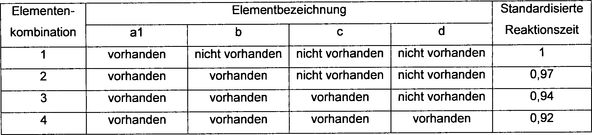
Aus
der Tabelle 1 ist ersichtlich, dass durch geeignetes Anordnen des
Elementes b (
Die obigen Ergebnisse beziehen sich auf die Zeit, welche erforderlich ist, um den Zustand des Ventils aus dem geschlossenen Zustand in den geöffneten Zustand zu wechseln; es wurden jedoch dieselben Ergebnisse für die Zeit erzielt, welche notwendig ist, um den Zustand des Ventils aus dem geöffneten Zustand in den geschlossenen Zustand zu wechseln.The The above results refer to the time required is to change the state of the valve from the closed state to the opened one Change state; however, they did get the same results over time achieved, which is necessary to the state of the valve from the open Condition to change to the closed state.
In dem vorliegenden Beispiel wurden Ergebnisse gezeigt, welche das Element a1 verwendeten (wobei ein magnetischer Werkstoff verwendet wurde, der eine Eisen-Kobalt-Systemlegierung umfasst); sogar wenn ein Element a2 (bei Verwendung eines magnetischen Werkstoffs, umfassend eine Eisen-Nickel-Systemlegierung) an der Stelle des Elementes a1 verwendet wird, wurde jedoch bestätigt, dass ähnliche Ergebnisse zu denjenigen in der vorliegenden Erfindung erzielt wurden, wenn die Elemente b, c und d denselben magnetischen Werkstoff wie das Element a2 umfassten.In In the present example results were shown which are the Element a1 used (using a magnetic material which was an iron-cobalt system alloy includes); even if an element a2 (using a magnetic Material comprising an iron-nickel system alloy) at the Site of the element a1 is used, however, it was confirmed that similar Results were achieved to those in the present invention, when the elements b, c and d the same magnetic material as the Element a2 included.
In
der vorliegenden Ausführung
wiesen die Elemente b, c und d und der Aktuatorrumpf
(Ausführung 5)(Version 5)
In
der vorliegenden Ausführung
wird, wie in der
Im
größeren Detail
waren die Einstellungen derart, dass der äußere Durchmesser des Aktuatorrumpfes
Die
Spule
Als
ein Ergebnis, wenn die Spule
(Ausführung 6)(Version 6)
In
der vorliegenden Ausführung
wird ein Beispiel eines Zufuhr-/Auslasssystems für Fluid, welches derart ausgeführt ist,
dass es das Fluidregelventil der vorliegenden Erfindung verwendet,
in der
Die
Zudem wird in dem Fall des verminderten Druckzustandes innerhalb der Einrichtung, wenn das Gas, welches normalerweise aus der Gasquelle zugeführt wird, ersetzt wird, das Ventil E zuerst geschlossen, und danach wird das Ventil D geschlossen, und dann wird das Ventil C geöffnet, und die Ventile werden in der Reihenfolge B, A geschaltet (weil das Gas, welches aus der Gasquelle zugeführt wird, einen höheren Druck als das Entleerungsgas aufweist). Wenn jedoch Ventile, in welchen die Reaktionsgeschwindigkeit langsam ist, wie bei herkömmlichen Luftdruckventilen, verwendet werden, werden große Unregelmäßigkeiten in den Betätigungszeiten der verschiedenen Ventile erzeugt, so dass Phänomene, wie zum Beispiel die Mischung von Auslassgasen (wenn das Ventil C öffnet, bevor die Ventile E und D geschlossen sind) oder die Mischung von Fluid (ein Entleerungsgas oder ein Gas aus der Gasquelle) (wenn die Öffnungs- und Schließreihenfolge der Ventile A und B umgekehrt wird) auftreten können. Zudem können ähnliche Phänomene auftreten, wenn die Art des Gases aus der Gasquelle geändert wird.moreover is in the case of the reduced pressure state within the device, if the gas that is normally supplied from the gas source is replaced, the valve E first closed, and then the Valve D is closed, and then the valve C is opened, and the valves are switched in the order B, A (because the Gas, which is supplied from the gas source, a higher pressure as the purge gas has). However, if valves in which the reaction rate is slow, as with conventional ones Air pressure valves, used, will be large irregularities in the operating times of the various valves generated, so that phenomena, such as the Mixture of outlet gases (when valve C opens before valves E and D are closed) or the mixture of fluid (a purge gas or a gas from the gas source) (if the opening and closing order the valves A and B is reversed) may occur. In addition, similar phenomena occur when the type of gas is changed from the gas source.
In Systemen, welche herkömmliche Ventile des Luftdrucktyps verwenden, wurde, um diese Probleme zu überwinden, die Länge der Instrumentierungsröhren geeignet verändert, und dadurch wurde die Zeitregulierung der Unregelmäßigkeiten in der Betriebszeit von jedem Ventil ausgeführt.In Systems which are conventional To use air pressure type valves to overcome these problems, the length the instrumentation tubes suitably changed, and thereby became the time regulation of the irregularities performed in the operating time of each valve.
Auf der anderen Seite, wenn ein solches System dadurch realisiert wird, dass die Fluidregelventile der vorliegenden Erfindung verwendet werden, ist ein Gasschalten mit einer schnellen Reaktionszeit von einigen wenigen Millisekunden möglich, wobei die Fluidregelventile der vorliegenden Erfindung verwendet werden, so dass es möglich ist, die Probleme, wie zum Beispiel eine Rückströmung und eine Rückverteilung, welche durch die herkömmlichen Systeme erzeugt werden, überwunden werden, und das Instrumentierungssystem, welches herkömmlich erforderlich war, wurde unnötig, so dass das Volumen, welches durch das existierende Gassystem eingenommen wird, erheblich reduziert werden kann.On the other hand, if such a system is realized by that uses the fluid control valves of the present invention is a gas switching with a fast response time of possible within a few milliseconds, wherein the fluid control valves of the present invention are used so that it is possible is the problems, such as a backflow and a redistribution, which by the conventional ones Systems are generated, overcome and the instrumentation system which is traditionally required was, became unnecessary, so that the volume occupied by the existing gas system will be, can be significantly reduced.
(Ausführung 7)(Version 7)
In
der vorliegenden Ausführung,
wobei die
Das
Zufuhr- und Auslasssystem für
Fluid ist auf eine solche Art und Weise ausgeführt, dass die Steuerung des Öffnens und
Schließens
einer Vielzahl (maximal näherungsweise
Die
Steuervorrichtungseinheit
Zudem
sind der Steuercomputer
In
anderen Worten, wenn das Betätigungssignal
S in die Steuervorrichtungseinheit
Zudem,
wenn es notwendig ist, wird ein Signal P, welches den Betriebszustand
von jedem Fluidregelventil anzeigt, von den Öffnungs- und Schließungsdetektoren
In
der Steuereinheit
In
anderen Worten, die Antriebseinheit von jedem Fluidregelventil kann
schnell unter einer hohen Anziehkraft betrieben werden, so dass
ein großer
Erregerstrom I bei der Initiierung der Betätigungen erforderlich ist.
Weil jedoch der Spalt G mit dem Öffnen
des Ventils kleiner wird, ist es, um den notwendigen Erregerstrom I
zu reduzieren und einen Stromverbrauch und das Überhitzen der Spule
Zudem
drückt
die Membran
Aus
diesem Grund stellt die Steuereinheit
Als
ein Ergebnis wird der Stromverbrauch in den Antriebseinheiten von
jedem Fluidregelventil reduziert, und ein Schaden an dem Kern
Wenn zum Beispiel die obere Grenze für die Temperatur auf 30°C eingestellt ist, dann ist es nicht möglich, wenn die Zeit, während welcher der Strom anfänglich geleitet wird (der Zustand des maximalen Erregerstroms), 0,1 Sekunden beträgt, die wiederholten Öffnungs- und Schließungsperioden der Fluidregelventile auf weniger als näherungsweise 3,6 Sekunden zu setzen, und wenn die Öffnungs- und Schließungsperioden auf 3,6 Sekunden oder weniger eingestellt werden, wird der Anstieg der Temperatur 30°C überschreiten.If for example, the upper limit for the temperature at 30 ° C is set, then it is not possible when the time during which the current initially is passed (the state of maximum excitation current), 0.1 seconds is, the repeated opening and closing periods the fluid control valves to less than approximately 3.6 seconds set, and when the opening and closing periods set to 3.6 seconds or less will increase exceed the temperature 30 ° C.
Im
Gegensatz dazu, wenn die anfängliche
Periode des Stromes auf 0,01 Sekunden eingestellt wird, wie in der
Weil
zudem die Steuerung eines weichen Landens der Membran
Die
Zeitsteuerung der erneuten Verstärkung
des Erregerstromes I in der
Ferner
kann als die Steuerung des sanften Landens ein Verfahren verwendet
werden, in welchem ein physikalisches Steuerverfahren an Stelle
einer elektrischen Steuerung verwendet wird; zum Beispiel kann der untere
innere Raum des Aktuatorrumpfes
Obwohl
es in der Ausführung,
die in der
In
dem Fluidregelventil aus der
Die
In
dem Fluidregelventil aus der
Auf
der anderen Seite, wenn die Spule
Der
Aufbau des Fluidregelventils aus der
Die
Durch Installieren eines Balges um den Ventilhalter herum, wird ein Fluidregelventil erzielt, welches eine verbesserte Haltbarkeit beim Öffnen und Schließen des Ventils aufweist.By Installing a bellows around the valve holder becomes a fluid control valve achieved which improved durability when opening and Shut down of the valve.
Industrielle Anwendbarkeit Industrial applicability
Wie oben beschrieben worden ist, werden durch die vorliegende Erfindung ein Fluidregelventil und ein Zufuhr-/-Auslasssystem für Fluid erzielt, bei welchem es möglich ist, ein Fluid stabil bei einem Druck von näherungsweise 10 kg/cm2 zu regeln, bei welchem die Ventilreaktionszeit schnell ist, bei einigen wenigen Millisekunden liegt, und bei welchen die Miniaturisierung des Ventils möglich ist, und in welchen es eine kleine Gasgegenströmung gibt, wenn die Konstruktion eine Vielzahl von Ventilen beinhaltet.As described above, the present invention achieves a fluid control valve and a fluid supply / discharge system in which it is possible to stably control a fluid at a pressure of approximately 10 kg / cm 2 , at which the valve reaction time is fast, is a few milliseconds, and where miniaturization of the valve is possible, and in which there is a small countercurrent flow when the design includes a plurality of valves.
Claims (3)
Applications Claiming Priority (6)
| Application Number | Priority Date | Filing Date | Title |
|---|---|---|---|
| JP33486696 | 1996-12-01 | ||
| JP33486696 | 1996-12-01 | ||
| JP32127696 | 1996-12-02 | ||
| JP32127696 | 1996-12-02 | ||
| JP32399596 | 1996-12-04 | ||
| JP32399596 | 1996-12-04 |
Publications (2)
| Publication Number | Publication Date |
|---|---|
| DE69737377D1 DE69737377D1 (en) | 2007-03-29 |
| DE69737377T2 true DE69737377T2 (en) | 2007-11-29 |
Family
ID=27339839
Family Applications (4)
| Application Number | Title | Priority Date | Filing Date |
|---|---|---|---|
| DE1997635280 Expired - Lifetime DE69735280T2 (en) | 1996-12-01 | 1997-12-01 | Control valve and liquid supply / drainage system |
| DE1997632976 Expired - Lifetime DE69732976T2 (en) | 1996-12-01 | 1997-12-01 | FLUID CONTROL VALVE AND FLUID IN / OUT FLUSH SYSTEM |
| DE1997637841 Expired - Lifetime DE69737841T2 (en) | 1996-12-01 | 1997-12-01 | Control valve and liquid supply / drainage system |
| DE1997637377 Expired - Lifetime DE69737377T2 (en) | 1996-12-01 | 1997-12-01 | Control valve and liquid supply / drainage system |
Family Applications Before (3)
| Application Number | Title | Priority Date | Filing Date |
|---|---|---|---|
| DE1997635280 Expired - Lifetime DE69735280T2 (en) | 1996-12-01 | 1997-12-01 | Control valve and liquid supply / drainage system |
| DE1997632976 Expired - Lifetime DE69732976T2 (en) | 1996-12-01 | 1997-12-01 | FLUID CONTROL VALVE AND FLUID IN / OUT FLUSH SYSTEM |
| DE1997637841 Expired - Lifetime DE69737841T2 (en) | 1996-12-01 | 1997-12-01 | Control valve and liquid supply / drainage system |
Country Status (9)
| Country | Link |
|---|---|
| US (2) | US6193212B1 (en) |
| EP (4) | EP1666780B1 (en) |
| JP (1) | JP3845454B2 (en) |
| KR (1) | KR100495897B1 (en) |
| AT (4) | ATE365292T1 (en) |
| DE (4) | DE69735280T2 (en) |
| IL (1) | IL129792A (en) |
| TW (2) | TW479773U (en) |
| WO (1) | WO1998025062A1 (en) |
Families Citing this family (55)
| Publication number | Priority date | Publication date | Assignee | Title |
|---|---|---|---|---|
| US6537505B1 (en) * | 1998-02-20 | 2003-03-25 | Bio Dot, Inc. | Reagent dispensing valve |
| DE19922423A1 (en) * | 1999-05-14 | 2000-11-30 | Siemens Ag | Electromechanical actuator |
| US6293516B1 (en) | 1999-10-21 | 2001-09-25 | Arichell Technologies, Inc. | Reduced-energy-consumption actuator |
| US6739573B1 (en) * | 1999-10-28 | 2004-05-25 | Siemens Canada Limited | Canister purge valve noise attenuation |
| DE69931787T2 (en) * | 1999-11-11 | 2007-05-24 | The Provost, Fellows And Scholars Of The College Of The Holy And Undivided Trinity Of Queen Elizabeth Near Dublin | Device and method for administration of drops |
| US20070241298A1 (en) | 2000-02-29 | 2007-10-18 | Kay Herbert | Electromagnetic apparatus and method for controlling fluid flow |
| US6305662B1 (en) | 2000-02-29 | 2001-10-23 | Arichell Technologies, Inc. | Reduced-energy-consumption actuator |
| US6948697B2 (en) | 2000-02-29 | 2005-09-27 | Arichell Technologies, Inc. | Apparatus and method for controlling fluid flow |
| DE10062487C1 (en) * | 2000-12-14 | 2002-03-07 | Gruner Ag | Electromagnetic valve e.g. for gas measuring device, has guide element fully enclosing valve body in its movement direction for preventing manipulation |
| US6669909B2 (en) * | 2001-03-26 | 2003-12-30 | Allegro Technologies Limited | Liquid droplet dispensing |
| DE10124847A1 (en) * | 2001-05-22 | 2002-11-28 | Abb Patent Gmbh | Operating actuator drive e.g. for pipeline, involves maximum actuation speed during first phase, and reducing actuation speed continuously with defined gradient from predefined position in second phase |
| JP2003156169A (en) * | 2001-09-04 | 2003-05-30 | Denso Corp | Electromagnetic fluid control device |
| US7222636B2 (en) * | 2002-08-20 | 2007-05-29 | Applied Materials, Inc. | Electronically actuated valve |
| US6749136B1 (en) * | 2002-11-26 | 2004-06-15 | Orbit Irrigation Products, Inc. | Enhanced sprinkler valving apparatus and method |
| US6907897B2 (en) | 2003-06-26 | 2005-06-21 | Planar Systems, Inc. | Diaphragm valve for high-temperature precursor supply in atomic layer deposition |
| US7021330B2 (en) * | 2003-06-26 | 2006-04-04 | Planar Systems, Inc. | Diaphragm valve with reliability enhancements for atomic layer deposition |
| US6941963B2 (en) * | 2003-06-26 | 2005-09-13 | Planar Systems, Inc. | High-speed diaphragm valve for atomic layer deposition |
| JP4383933B2 (en) * | 2004-03-15 | 2009-12-16 | 三菱電機株式会社 | Method for manufacturing output shaft connection structure of electric control valve |
| US7628860B2 (en) * | 2004-04-12 | 2009-12-08 | Mks Instruments, Inc. | Pulsed mass flow delivery system and method |
| JP2005299811A (en) * | 2004-04-13 | 2005-10-27 | Tgk Co Ltd | Fluid control valve |
| DE102005008010B4 (en) | 2005-02-22 | 2022-01-27 | Zf Friedrichshafen Ag | Method for increasing the spontaneity when shifting gears in an automatic transmission or an automated manual transmission |
| JP4743763B2 (en) * | 2006-01-18 | 2011-08-10 | 株式会社フジキン | Piezoelectric element driven metal diaphragm type control valve |
| DE102007023716A1 (en) * | 2006-11-02 | 2008-05-08 | Continental Teves Ag & Co. Ohg | Proportional control valve |
| KR100927896B1 (en) * | 2007-09-19 | 2009-11-25 | 주식회사 세 바 | Fluid control valve |
| JP4644242B2 (en) * | 2007-12-10 | 2011-03-02 | 忠弘 大見 | How to use vacuum exhaust valve |
| US8430378B2 (en) * | 2008-05-30 | 2013-04-30 | South Bend Controls Holdings Llc | High flow proportional valve |
| EP2159462B1 (en) * | 2008-09-01 | 2015-01-14 | Siemens Aktiengesellschaft | Coupling element for connecting an actuator to a valve |
| US20100212763A1 (en) * | 2009-02-24 | 2010-08-26 | Means Stephen R | Well gauging system and method |
| KR100924265B1 (en) | 2009-05-28 | 2009-10-30 | 신우공업 주식회사 | Electromagnetic Control Valve |
| CN101839362B (en) * | 2010-06-18 | 2011-06-15 | 欧好光电控制技术(上海)有限公司 | Normally closed semiautomatic gas emergency cut-off magnetic valve |
| EP2453122B1 (en) | 2010-11-12 | 2016-09-07 | Hitachi, Ltd. | Method and control apparatus for controlling a high-pressure fuel supply pump configured to supply pressurized fuel to an internal combustion engine |
| DE102010061271A1 (en) * | 2010-12-15 | 2012-06-21 | Contitech Schlauch Gmbh | Heatable connection device for media-carrying, electrically heatable hoses |
| US9353886B2 (en) | 2011-12-29 | 2016-05-31 | Koge Micro Tech Co., Ltd. | Solenoid valve having air tap structure |
| TWI451029B (en) * | 2011-12-29 | 2014-09-01 | Koge Electronics Co Ltd | Solenoid valve having air tap structure |
| RU2516057C2 (en) * | 2012-06-14 | 2014-05-20 | Рауф Рахимович Сафаров | Bypass valve of discrete action with magnetic fixation, relief and position control |
| CN102777653B (en) * | 2012-07-25 | 2013-11-06 | 欧好光电控制技术(上海)有限公司 | Industrial electromagnetic type gas emergency cut-off valve containing energy storage valve closing module |
| US9454158B2 (en) | 2013-03-15 | 2016-09-27 | Bhushan Somani | Real time diagnostics for flow controller systems and methods |
| CN103672147A (en) * | 2013-11-28 | 2014-03-26 | 武汉工程大学 | Fluid pressure-stabilizing regulating valve |
| US9911561B2 (en) | 2015-11-13 | 2018-03-06 | Target Rock Division Of Curtiss-Wright Flow Control Corporation | Solenoid current control with fault detection, override, and shutdown features |
| NL2016009B1 (en) * | 2015-12-22 | 2017-07-03 | Eskens Solutions B V | Method for dosing a color paste. |
| RU2617651C1 (en) * | 2016-06-01 | 2017-04-25 | Иван Николаевич Селиванов | Magnet controlled valve |
| DE102016112115A1 (en) * | 2016-07-01 | 2018-01-04 | Bürkert Werke GmbH | Valve linear drive and valve |
| US10993546B2 (en) * | 2016-10-28 | 2021-05-04 | Sleep Number Corporation | Noise reducing plunger |
| US10983537B2 (en) | 2017-02-27 | 2021-04-20 | Flow Devices And Systems Inc. | Systems and methods for flow sensor back pressure adjustment for mass flow controller |
| JP6153684B1 (en) * | 2017-04-03 | 2017-06-28 | 伸和コントロールズ株式会社 | Solenoid valve with durability against oxygen, hydrogen and water |
| GB2564703A (en) * | 2017-07-21 | 2019-01-23 | Weir Group Ip Ltd | Valve |
| CN110892357A (en) * | 2017-07-31 | 2020-03-17 | 株式会社富士金 | Fluid control system and flow rate measurement method |
| CN107676495B (en) * | 2017-09-21 | 2019-03-26 | 安徽荣达阀门有限公司 | A kind of valve system detecting water quality |
| WO2019065117A1 (en) * | 2017-09-29 | 2019-04-04 | 株式会社フジキン | Manual valve device and fluid control device |
| US10808858B2 (en) | 2017-10-17 | 2020-10-20 | Automotive Technologies International, Inc. | High speed valve |
| US11486313B2 (en) * | 2019-06-14 | 2022-11-01 | Hamilton Sundstrand Corporation | Linear electric air valve |
| CN110701312A (en) * | 2019-10-15 | 2020-01-17 | 中冶华天工程技术有限公司 | High-pressure dry oil pneumatic control valve |
| CN113447261A (en) * | 2021-07-16 | 2021-09-28 | 上海廷本流体控制有限公司 | Detection system and detection method for safety valve |
| US11832728B2 (en) | 2021-08-24 | 2023-12-05 | Sleep Number Corporation | Controlling vibration transmission within inflation assemblies |
| KR102585781B1 (en) | 2021-09-08 | 2023-10-05 | 주식회사 현대케피코 | Fuel tank isolation valve of vehicle |
Family Cites Families (34)
| Publication number | Priority date | Publication date | Assignee | Title |
|---|---|---|---|---|
| US3174716A (en) * | 1962-10-15 | 1965-03-23 | Salter Jack Nelson | Magnetostrictive multiplier device |
| US3633869A (en) * | 1970-07-31 | 1972-01-11 | Danfoss As | Solenoid valve with adjustable stroke |
| US4165762A (en) * | 1978-02-21 | 1979-08-28 | International Telephone And Telegraph Corporation | Latching valve |
| EP0006843B2 (en) * | 1978-07-06 | 1987-09-23 | Bürkert GmbH | Electronically controlled magnetic valve |
| JPS59133884A (en) * | 1983-01-20 | 1984-08-01 | Matsushita Electric Ind Co Ltd | Solenoid valve |
| DE3437487A1 (en) * | 1984-10-12 | 1986-04-17 | H. Kuhnke Gmbh Kg, 2427 Malente | BISTABLE SOLENOID VALVE |
| US4757943A (en) * | 1984-12-24 | 1988-07-19 | Naiad Company Usa | Method and apparatus for controlling the temperature of a liquid |
| JPS6220980A (en) * | 1985-07-18 | 1987-01-29 | Diesel Kiki Co Ltd | Solenoid-controlled valve |
| JPS62188872A (en) * | 1986-02-13 | 1987-08-18 | Tokyo Keiki Co Ltd | Communication control system for fluid control valve |
| US4813647A (en) * | 1986-11-24 | 1989-03-21 | Nippondenso Co., Ltd. | Electromagnetic actuator for controlling fluid flow |
| US4768555A (en) * | 1987-04-30 | 1988-09-06 | Allied-Signal Inc. | Solenoid valve |
| JPS63318380A (en) | 1987-06-23 | 1988-12-27 | Hitachi Ltd | Magnetic circuit member of solenoid valve and manufacture thereof |
| US4829947A (en) * | 1987-08-12 | 1989-05-16 | General Motors Corporation | Variable lift operation of bistable electromechanical poppet valve actuator |
| JPH01241104A (en) * | 1988-03-22 | 1989-09-26 | Tokin Corp | Attractive electromagnet |
| JP2635663B2 (en) * | 1988-03-23 | 1997-07-30 | 日立金属株式会社 | Printer head |
| JPH0231088A (en) * | 1988-07-20 | 1990-02-01 | Matsushita Electric Ind Co Ltd | Solenoid valve |
| JPH0361776A (en) * | 1989-07-26 | 1991-03-18 | Takasago Denki Kogyo Kk | Dc solenoid valve |
| US4988907A (en) * | 1990-01-30 | 1991-01-29 | Lucas Ledex Inc. | Independent redundant force motor |
| EP0445340B1 (en) * | 1990-03-09 | 1994-12-14 | Siemens Aktiengesellschaft | Valve with piezoelectric drive |
| IT220662Z2 (en) * | 1990-10-31 | 1993-10-08 | Elasis Sistema Ricerca Fita Nel Mezzogiorno Soc.Consortile P.A. | IMPROVEMENTS TO THE PILOT VALVE AND TO THE RELATED STILL OF ORDER AN ELECTROMAGNETIC INJECTOR FOR FUEL INJECTION SYSTEMS OF INTERNAL COMBUSTION ENGINES |
| DE4036491C2 (en) * | 1990-11-16 | 1994-01-27 | Danfoss As | magnetic valve |
| JP2611539B2 (en) * | 1990-11-19 | 1997-05-21 | 三菱マテリアル株式会社 | Valve operated by a small force |
| WO1993005326A1 (en) * | 1991-09-10 | 1993-03-18 | Smc Kabushiki Kaisha | Fluid pressure machine |
| JPH07500408A (en) * | 1992-08-19 | 1995-01-12 | フェスト アクツィエンゲゼルシャフト ウント コー | electro pneumatic controller |
| JPH06207684A (en) * | 1992-08-28 | 1994-07-26 | Taiheiyo Kogyo Kk | Noiseless solenoid valve |
| US5548263A (en) * | 1992-10-05 | 1996-08-20 | Aura Systems, Inc. | Electromagnetically actuated valve |
| US5333643A (en) * | 1993-03-24 | 1994-08-02 | South Bend Controls, Inc. | Solenoid valve |
| DE4310984A1 (en) * | 1993-04-03 | 1994-10-06 | Rexroth Mannesmann Gmbh | Electromagnetically operable hydraulic control valve |
| DE69501863T2 (en) * | 1994-09-09 | 1998-07-23 | Gen Motors Corp | Actuator for an exhaust gas recirculation valve |
| US5501425A (en) * | 1994-09-21 | 1996-03-26 | Marotta Scientific Controls, Inc. | Magnetostrictively actuated valve |
| DE4439495C2 (en) * | 1994-10-25 | 1997-05-28 | Liebherr Aerospace Gmbh | Electromagnetically controlled directional seat valve |
| JP3437300B2 (en) * | 1994-12-02 | 2003-08-18 | Smc株式会社 | Solenoid valve control device |
| DE19631909A1 (en) * | 1995-08-08 | 1997-02-13 | Fev Motorentech Gmbh & Co Kg | Adjustment of null position of piston engine valve actuator armature - has adjustment of armature element position while measuring and comparing inductance values of electromagnets |
| JP3552849B2 (en) * | 1996-07-12 | 2004-08-11 | 株式会社東芝 | Hydraulic drive system for control rod drive mechanism and its operation method |
-
1997
- 1997-11-28 TW TW89222640U patent/TW479773U/en not_active IP Right Cessation
- 1997-11-28 TW TW91206683U patent/TW506498U/en unknown
- 1997-12-01 EP EP20060005025 patent/EP1666780B1/en not_active Expired - Lifetime
- 1997-12-01 EP EP20040021881 patent/EP1486710B1/en not_active Expired - Lifetime
- 1997-12-01 WO PCT/JP1997/004377 patent/WO1998025062A1/en active IP Right Grant
- 1997-12-01 US US09/308,922 patent/US6193212B1/en not_active Expired - Lifetime
- 1997-12-01 AT AT06005025T patent/ATE365292T1/en not_active IP Right Cessation
- 1997-12-01 JP JP52544198A patent/JP3845454B2/en not_active Expired - Fee Related
- 1997-12-01 DE DE1997635280 patent/DE69735280T2/en not_active Expired - Lifetime
- 1997-12-01 AT AT04021884T patent/ATE318384T1/en not_active IP Right Cessation
- 1997-12-01 EP EP97913482A patent/EP0942214B1/en not_active Expired - Lifetime
- 1997-12-01 DE DE1997632976 patent/DE69732976T2/en not_active Expired - Lifetime
- 1997-12-01 AT AT04021881T patent/ATE354048T1/en not_active IP Right Cessation
- 1997-12-01 DE DE1997637841 patent/DE69737841T2/en not_active Expired - Lifetime
- 1997-12-01 EP EP20040021884 patent/EP1486711B1/en not_active Expired - Lifetime
- 1997-12-01 DE DE1997637377 patent/DE69737377T2/en not_active Expired - Lifetime
- 1997-12-01 IL IL12979297A patent/IL129792A/en not_active IP Right Cessation
- 1997-12-01 KR KR10-1999-7004536A patent/KR100495897B1/en not_active IP Right Cessation
- 1997-12-01 AT AT97913482T patent/ATE292766T1/en not_active IP Right Cessation
-
2000
- 2000-07-27 US US09/627,784 patent/US6394415B1/en not_active Expired - Lifetime
Also Published As
| Publication number | Publication date |
|---|---|
| EP1486710A1 (en) | 2004-12-15 |
| DE69735280T2 (en) | 2006-10-12 |
| KR20000057204A (en) | 2000-09-15 |
| ATE354048T1 (en) | 2007-03-15 |
| EP1486711A3 (en) | 2004-12-22 |
| ATE365292T1 (en) | 2007-07-15 |
| EP0942214A1 (en) | 1999-09-15 |
| IL129792A (en) | 2002-12-01 |
| DE69737841D1 (en) | 2007-08-02 |
| EP0942214B1 (en) | 2005-04-06 |
| DE69737377D1 (en) | 2007-03-29 |
| EP1486710B1 (en) | 2007-02-14 |
| WO1998025062A1 (en) | 1998-06-11 |
| DE69737841T2 (en) | 2008-02-07 |
| US6394415B1 (en) | 2002-05-28 |
| EP1486711A2 (en) | 2004-12-15 |
| EP1666780B1 (en) | 2007-06-20 |
| IL129792A0 (en) | 2000-02-29 |
| KR100495897B1 (en) | 2005-06-17 |
| DE69732976D1 (en) | 2005-05-12 |
| ATE318384T1 (en) | 2006-03-15 |
| EP1666780A1 (en) | 2006-06-07 |
| TW479773U (en) | 2002-03-11 |
| TW506498U (en) | 2002-10-11 |
| US6193212B1 (en) | 2001-02-27 |
| DE69732976T2 (en) | 2006-02-16 |
| ATE292766T1 (en) | 2005-04-15 |
| EP1486711B1 (en) | 2006-02-22 |
| EP0942214A4 (en) | 2002-07-31 |
| JP3845454B2 (en) | 2006-11-15 |
| DE69735280D1 (en) | 2006-04-27 |
Similar Documents
| Publication | Publication Date | Title |
|---|---|---|
| DE69737377T2 (en) | Control valve and liquid supply / drainage system | |
| DE60108519T2 (en) | ELECTROMAGNETIC MEMBRANE VALVE AND METHOD FOR CONTROLLING FLUID FLOW | |
| DE19525384C2 (en) | Double safety solenoid valve | |
| DE2450094C3 (en) | ||
| EP2016319B2 (en) | Valve with an electromagnetic drive | |
| EP0010683A1 (en) | Regulation valve for the heating circuit of an automobile and method for its manufacture, particularly its adjustment | |
| EP0893635A1 (en) | Solenoid valve device | |
| DE112009004389T5 (en) | Pilot operated water valve | |
| EP2385291A1 (en) | Assembly of pulse-modulated quick-switching valves, tank system, method for producing a requested mass flow and use of a tank system | |
| EP0080180B1 (en) | Gas fittings with a solenoid valve and a pressure governor | |
| EP3080501B1 (en) | Household appliance having a solenoid valve | |
| DE2856113A1 (en) | ELECTROMAGNETIC VALVE | |
| EP0413172B1 (en) | Method to control the pressure with a magnetic valve. | |
| DE1775108A1 (en) | Regulation and control device, in particular for washing machines, dishwashers or the like. | |
| DE4230201A1 (en) | SERVO PRESSURE REGULATOR | |
| DE60223627T2 (en) | Control method of an electromagnetic actuator for controlling a motor valve from the position stop out | |
| EP0139839A1 (en) | Solenoid-operated valve | |
| EP2915775B1 (en) | Device and method for filling a container with a filling product | |
| DE2842382C2 (en) | ||
| DE856063C (en) | Liquid flow regulator | |
| DE102013225537B4 (en) | Household appliance with a solenoid valve | |
| EP0193108B1 (en) | Pneumatic interval switching mechanism | |
| DE1502290B2 (en) | Safety device for the operation of a device operated by means of electricity, in particular the brake and clutch of a press | |
| DE1909873A1 (en) | Electromagnetically operated drive device for a flow control valve | |
| EP2209993B1 (en) | Actively controlled valve and method of operating said valve |
Legal Events
| Date | Code | Title | Description |
|---|---|---|---|
| 8364 | No opposition during term of opposition |