JP2005299811A - Fluid control valve - Google Patents
Fluid control valve Download PDFInfo
- Publication number
- JP2005299811A JP2005299811A JP2004117644A JP2004117644A JP2005299811A JP 2005299811 A JP2005299811 A JP 2005299811A JP 2004117644 A JP2004117644 A JP 2004117644A JP 2004117644 A JP2004117644 A JP 2004117644A JP 2005299811 A JP2005299811 A JP 2005299811A
- Authority
- JP
- Japan
- Prior art keywords
- valve
- fluid
- valve seat
- fluid control
- seat
- Prior art date
- Legal status (The legal status is an assumption and is not a legal conclusion. Google has not performed a legal analysis and makes no representation as to the accuracy of the status listed.)
- Pending
Links
- 239000012530 fluid Substances 0.000 title claims abstract description 63
- 238000011144 upstream manufacturing Methods 0.000 claims description 24
- 230000002457 bidirectional effect Effects 0.000 claims description 4
- 230000001105 regulatory effect Effects 0.000 claims description 2
- 239000003507 refrigerant Substances 0.000 description 44
- 238000003780 insertion Methods 0.000 description 17
- 230000037431 insertion Effects 0.000 description 17
- 230000006835 compression Effects 0.000 description 12
- 238000007906 compression Methods 0.000 description 12
- 238000004891 communication Methods 0.000 description 10
- 230000002093 peripheral effect Effects 0.000 description 9
- 230000007423 decrease Effects 0.000 description 8
- 238000005057 refrigeration Methods 0.000 description 7
- 230000000694 effects Effects 0.000 description 6
- XEEYBQQBJWHFJM-UHFFFAOYSA-N Iron Chemical group [Fe] XEEYBQQBJWHFJM-UHFFFAOYSA-N 0.000 description 2
- 230000004308 accommodation Effects 0.000 description 2
- 230000000295 complement effect Effects 0.000 description 2
- 239000002826 coolant Substances 0.000 description 2
- 230000000149 penetrating effect Effects 0.000 description 2
- 238000013459 approach Methods 0.000 description 1
- 230000008602 contraction Effects 0.000 description 1
- 230000001276 controlling effect Effects 0.000 description 1
- 238000002788 crimping Methods 0.000 description 1
- 230000005611 electricity Effects 0.000 description 1
- 239000000463 material Substances 0.000 description 1
- 230000013011 mating Effects 0.000 description 1
- 239000002184 metal Substances 0.000 description 1
- 229910052751 metal Inorganic materials 0.000 description 1
- 238000012545 processing Methods 0.000 description 1
- 238000000926 separation method Methods 0.000 description 1
- 239000007787 solid Substances 0.000 description 1
- 238000012360 testing method Methods 0.000 description 1
- XLYOFNOQVPJJNP-UHFFFAOYSA-N water Substances O XLYOFNOQVPJJNP-UHFFFAOYSA-N 0.000 description 1
Images

Classifications
-
- F—MECHANICAL ENGINEERING; LIGHTING; HEATING; WEAPONS; BLASTING
- F16—ENGINEERING ELEMENTS AND UNITS; GENERAL MEASURES FOR PRODUCING AND MAINTAINING EFFECTIVE FUNCTIONING OF MACHINES OR INSTALLATIONS; THERMAL INSULATION IN GENERAL
- F16K—VALVES; TAPS; COCKS; ACTUATING-FLOATS; DEVICES FOR VENTING OR AERATING
- F16K31/00—Actuating devices; Operating means; Releasing devices
- F16K31/02—Actuating devices; Operating means; Releasing devices electric; magnetic
- F16K31/06—Actuating devices; Operating means; Releasing devices electric; magnetic using a magnet, e.g. diaphragm valves, cutting off by means of a liquid
- F16K31/0686—Braking, pressure equilibration, shock absorbing
- F16K31/0693—Pressure equilibration of the armature
-
- F—MECHANICAL ENGINEERING; LIGHTING; HEATING; WEAPONS; BLASTING
- F25—REFRIGERATION OR COOLING; COMBINED HEATING AND REFRIGERATION SYSTEMS; HEAT PUMP SYSTEMS; MANUFACTURE OR STORAGE OF ICE; LIQUEFACTION SOLIDIFICATION OF GASES
- F25B—REFRIGERATION MACHINES, PLANTS OR SYSTEMS; COMBINED HEATING AND REFRIGERATION SYSTEMS; HEAT PUMP SYSTEMS
- F25B41/00—Fluid-circulation arrangements
- F25B41/30—Expansion means; Dispositions thereof
- F25B41/31—Expansion valves
- F25B41/34—Expansion valves with the valve member being actuated by electric means, e.g. by piezoelectric actuators
- F25B41/345—Expansion valves with the valve member being actuated by electric means, e.g. by piezoelectric actuators by solenoids
-
- F—MECHANICAL ENGINEERING; LIGHTING; HEATING; WEAPONS; BLASTING
- F25—REFRIGERATION OR COOLING; COMBINED HEATING AND REFRIGERATION SYSTEMS; HEAT PUMP SYSTEMS; MANUFACTURE OR STORAGE OF ICE; LIQUEFACTION SOLIDIFICATION OF GASES
- F25B—REFRIGERATION MACHINES, PLANTS OR SYSTEMS; COMBINED HEATING AND REFRIGERATION SYSTEMS; HEAT PUMP SYSTEMS
- F25B41/00—Fluid-circulation arrangements
- F25B41/30—Expansion means; Dispositions thereof
- F25B41/38—Expansion means; Dispositions thereof specially adapted for reversible cycles, e.g. bidirectional expansion restrictors
-
- Y—GENERAL TAGGING OF NEW TECHNOLOGICAL DEVELOPMENTS; GENERAL TAGGING OF CROSS-SECTIONAL TECHNOLOGIES SPANNING OVER SEVERAL SECTIONS OF THE IPC; TECHNICAL SUBJECTS COVERED BY FORMER USPC CROSS-REFERENCE ART COLLECTIONS [XRACs] AND DIGESTS
- Y02—TECHNOLOGIES OR APPLICATIONS FOR MITIGATION OR ADAPTATION AGAINST CLIMATE CHANGE
- Y02B—CLIMATE CHANGE MITIGATION TECHNOLOGIES RELATED TO BUILDINGS, e.g. HOUSING, HOUSE APPLIANCES OR RELATED END-USER APPLICATIONS
- Y02B30/00—Energy efficient heating, ventilation or air conditioning [HVAC]
- Y02B30/70—Efficient control or regulation technologies, e.g. for control of refrigerant flow, motor or heating
-
- Y—GENERAL TAGGING OF NEW TECHNOLOGICAL DEVELOPMENTS; GENERAL TAGGING OF CROSS-SECTIONAL TECHNOLOGIES SPANNING OVER SEVERAL SECTIONS OF THE IPC; TECHNICAL SUBJECTS COVERED BY FORMER USPC CROSS-REFERENCE ART COLLECTIONS [XRACs] AND DIGESTS
- Y10—TECHNICAL SUBJECTS COVERED BY FORMER USPC
- Y10T—TECHNICAL SUBJECTS COVERED BY FORMER US CLASSIFICATION
- Y10T137/00—Fluid handling
- Y10T137/7722—Line condition change responsive valves
- Y10T137/7781—With separate connected fluid reactor surface
- Y10T137/7832—Plural valves biased closed
Landscapes
- Engineering & Computer Science (AREA)
- General Engineering & Computer Science (AREA)
- Mechanical Engineering (AREA)
- Physics & Mathematics (AREA)
- Thermal Sciences (AREA)
- Magnetically Actuated Valves (AREA)
- Lift Valve (AREA)
Abstract
Description
本発明は、上流側から導入された流体の流量を調整して下流側に導出する流体制御弁に関する。 The present invention relates to a fluid control valve that adjusts the flow rate of a fluid introduced from an upstream side and derives the fluid downstream.
従来より、流体の流路に配置されて上流側から導入された流体の流量を調整して下流側に導出する電磁弁が知られている(例えば特許文献1参照)。
このような電磁弁は、一般に、弁体を開閉駆動するソレノイドと、弁体によって流路の開閉を行う弁機構とから構成されている。ソレノイドは、外部より制御電流が供給される電磁コイルと、この電磁コイルの軸線位置に固定された固定鉄芯としてのコアと、電磁コイルの軸線位置にて軸線方向に進退自在に配置され、弁体と一体的に動作する可動鉄芯としてのプランジャと、電磁コイルの非通電時にプランジャを開弁又は閉弁方向へ付勢するスプリングとを備えている。また、弁機構は、ボディに穿設された2つのポートと、両ポート間をつなぐ流路に配置されてボディと一体に形成された弁座と、この弁座に対向するよう配置され、プランジャとともに開閉駆動される弁体とを備えている。
2. Description of the Related Art Conventionally, there is known an electromagnetic valve that is arranged in a fluid flow path and adjusts the flow rate of a fluid introduced from the upstream side and derives it downstream (see, for example, Patent Document 1).
Such a solenoid valve is generally composed of a solenoid that opens and closes a valve body and a valve mechanism that opens and closes a flow path using the valve body. The solenoid is arranged in such a way that an electromagnetic coil to which a control current is supplied from the outside, a core as a fixed iron core fixed to the axial position of the electromagnetic coil, and an axial position at which the electromagnetic coil can move forward and backward. A plunger as a movable iron core that operates integrally with the body, and a spring that biases the plunger in the valve opening or closing direction when the electromagnetic coil is not energized. The valve mechanism includes two ports formed in the body, a valve seat disposed in a flow path connecting the two ports and formed integrally with the body, and disposed so as to face the valve seat. And a valve body that is driven to open and close.
そして、ソレノイドへの通電制御により弁体の弁座からのリフト量を制御することにより、下流側に導出する流体の流量を調整している。
ところで、このような電磁弁における弁体は、流体から受ける圧力(流体圧力)と、スプリングによる付勢力と、ソレノイドによる電磁力とがバランスした位置に動作制御されることになる。しかし、弁体の弁座からのリフト量が大きくなるにつれて、弁体が実際に圧力を受ける面積(有効受圧面積)が減少するといった現象が生じ、その結果、弁体のリフトとともに圧力のバランスが変化し、流体の流量制御の精度が低下するといった問題があった。 By the way, the valve body in such an electromagnetic valve is controlled in a position where the pressure received from the fluid (fluid pressure), the urging force by the spring, and the electromagnetic force by the solenoid are balanced. However, as the lift amount of the valve body from the valve seat increases, the phenomenon that the valve body actually receives pressure (effective pressure receiving area) decreases, and as a result, the balance of pressure with the lift of the valve body is reduced. There is a problem that the accuracy of the flow rate control of the fluid is lowered.
尚、このような問題は弁体を電磁駆動する電磁弁に限らず、スプリング等の機械的機構と流体圧力とのバランスのみにより弁体のリフト量が調整される流体制御弁についても、同様に生じ得るものと考えられる。 This problem is not limited to the solenoid valve that electromagnetically drives the valve body, but also applies to a fluid control valve in which the lift amount of the valve body is adjusted only by the balance between the mechanical mechanism such as a spring and the fluid pressure. It is thought that it can occur.
本発明はこのような点に鑑みてなされたものであり、弁体の弁座からのリフト量に応じた流量制御の精度の低下を防止又は抑制できる流体制御弁を提供することを目的とする。 This invention is made in view of such a point, and it aims at providing the fluid control valve which can prevent or suppress the fall of the precision of the flow control according to the lift amount from the valve seat of a valve body. .
本発明では上記問題を解決するために、上流側から導入された流体の流量を調整して下流側に導出する流体制御弁において、内部に前記流体の流路が形成されたボディと、前記ボディ内に前記流路に沿って設けられた第1弁座及び第2弁座と、前記第1弁座及び前記第2弁座のそれぞれにほぼ同時に接離可能な第1弁部及び第2弁部が一体的に設けられ、前記ボディ内で支持されつつ進退し、各弁部の各弁座からのリフト量によって下流側へ流す前記流体の流量を調整する弁体と、前記弁体の開弁方向に作用する流体圧力を受ける開弁用受圧面と、前記弁体の閉弁方向に作用する流体圧力を受ける閉弁用受圧面とからなり、前記弁体に作用する流体圧力の少なくとも一部をキャンセルする圧力キャンセル構造と、
を備えたことを特徴とする流体制御弁が提供される。
In the present invention, in order to solve the above problem, in a fluid control valve for adjusting the flow rate of the fluid introduced from the upstream side and leading it to the downstream side, a body in which the fluid flow path is formed, and the body A first valve seat and a second valve seat provided along the flow path, and a first valve portion and a second valve which can be brought into and out of contact with the first valve seat and the second valve seat substantially simultaneously. A valve body that is integrally provided, moves forward and backward while being supported in the body, and adjusts the flow rate of the fluid that flows to the downstream side by the lift amount from each valve seat of each valve section, and the opening of the valve body A valve-opening pressure-receiving surface that receives fluid pressure acting in the valve direction and a valve-closing pressure-receiving surface that receives fluid pressure acting in the valve-closing direction of the valve body, and at least one of the fluid pressures acting on the valve body Pressure canceling structure to cancel the part,
A fluid control valve is provided.
尚、ここでいう「流体制御弁」には、電磁駆動により弁体を駆動する電磁弁のみならず、内部の機械的構成により弁体が駆動される制御弁なども含まれ得る。また、第1弁部及び第2弁部が第1弁座及び第2弁座のそれぞれに係止されるように着座する構成であってもよいし、第1弁部及び第2弁部が第1弁座及び第2弁座により形成される弁孔に摺動可能に挿入されて弁孔を閉じる構成であってもよい。 The “fluid control valve” mentioned here may include not only an electromagnetic valve that drives the valve body by electromagnetic drive, but also a control valve that drives the valve body by an internal mechanical configuration. Moreover, the structure which seats so that a 1st valve part and a 2nd valve part may be latched by each of a 1st valve seat and a 2nd valve seat may be sufficient, and a 1st valve part and a 2nd valve part are The valve hole may be configured to be slidably inserted into the valve hole formed by the first valve seat and the second valve seat.
このような流体制御弁においては、圧力キャンセル構造により弁体の開弁方向に作用する流体圧力の少なくとも一部がキャンセルされるため、簡易な構造であっても大きな前後差圧を取り扱うことができる。 In such a fluid control valve, at least a part of the fluid pressure acting in the valve opening direction of the valve body is canceled by the pressure canceling structure, so that even a simple structure can handle a large front-rear differential pressure. .
そして特に、弁体に一体に設けられた第1弁部及び第2弁部が、第1弁座及び前記第2弁座のそれぞれにほぼ同時に接離するように構成したため、後述する発明の実施の形態でも説明するように、各弁部のリフト時における有効受圧面積が変化による圧力バランスへの影響について、その少なくとも一部をキャンセルすることができる。 In particular, since the first valve portion and the second valve portion provided integrally with the valve body are configured to contact and separate from the first valve seat and the second valve seat substantially simultaneously, the invention described later is carried out. As will be described in the above embodiment, at least a part of the influence on the pressure balance due to the change in the effective pressure receiving area during the lift of each valve portion can be canceled.
特に、開弁時における第1弁部と第1弁座との間隙により形成される流路断面と、第2弁部と第2弁座との間隙により形成される流路断面とが、ほぼ同じ大きさになるように構成すると、その圧力バランスへの影響をほぼ完全にキャンセルすることができる。 In particular, the flow path cross section formed by the gap between the first valve portion and the first valve seat at the time of valve opening and the flow path cross section formed by the gap between the second valve portion and the second valve seat are approximately When configured to be the same size, the influence on the pressure balance can be canceled almost completely.
本発明の流体制御弁によれば、第1弁部及び第2弁部が第1弁座及び前記第2弁座のそれぞれにほぼ同時に接離して、各弁部のリフト時における圧力バランスへの影響を防止又は抑制するようにしたため、弁体のリフト量に応じた流量制御の精度の低下を防止又は抑制することができる。 According to the fluid control valve of the present invention, the first valve portion and the second valve portion are brought into and out of contact with the first valve seat and the second valve seat almost simultaneously, so that the pressure balance at the time of lift of each valve portion is achieved. Since the influence is prevented or suppressed, it is possible to prevent or suppress a decrease in accuracy of the flow rate control according to the lift amount of the valve body.
以下、本発明の実施の形態を、図面を参照して説明する。
[第1の実施の形態]
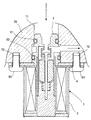
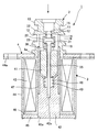
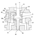
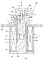
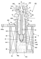
まず、本発明の第1の実施の形態について説明する。本実施の形態は、本発明の流体制御弁を車両用エアコンの冷凍サイクルに設置される膨張弁として構成したものである。図1は、この膨張弁が冷凍サイクルの配管本体に設置された様子を表す断面図であり、図2は、この膨張弁の単体の構成を表す断面図であり、図3は図2に示した膨張弁の弁体近傍を示す拡大図である。尚、以下の説明においては、冷媒(流体)の流れ方向を基準に上流側、下流側と表現することがあり、また、説明の便宜上、図示の状態を基準に上側、下側と表現することがある。
Hereinafter, embodiments of the present invention will be described with reference to the drawings.
[First Embodiment]
First, a first embodiment of the present invention will be described. In this embodiment, the fluid control valve of the present invention is configured as an expansion valve installed in a refrigeration cycle of a vehicle air conditioner. FIG. 1 is a cross-sectional view showing a state in which this expansion valve is installed in a pipe body of a refrigeration cycle, FIG. 2 is a cross-sectional view showing a single structure of this expansion valve, and FIG. 3 is shown in FIG. It is an enlarged view which shows the valve body vicinity of the expanded valve. In the following description, the flow direction of the refrigerant (fluid) may be expressed as the upstream side and the downstream side, and for convenience of description, the upper side and the lower side are expressed based on the illustrated state. There is.
図1に示すように、膨張弁1は、配管本体70の内部に組み付けられてその冷媒流路71に配置される弁本体2と、弁本体2に連設されて配管本体70の外部に露出するソレノイド3とから構成されている。これら弁本体2とソレノイド3との間には、外方に延びるフランジ状のプレート4が介装されており、膨張弁1は、このプレート4を介して配管本体70に固定される。
As shown in FIG. 1, the
図2に示すように、弁本体2は、内部に冷媒流路を形成する円筒状のボディ10と、ボディ10内で進退する円筒状の弁体20と、弁体20とともに弁機構を構成する長尺状の軸状部材30とから構成されている。
As shown in FIG. 2, the
ボディ10は、その上流部に半径方向内向きに突出した段部により形成される弁孔11が設けられ、その弁孔11の開口端部の周端縁により弁座12(第1弁座)が構成されている。また、このボディ10の弁座12よりも下流側の外周部には、冷媒通路を構成する通路溝13が周設されており、その通路溝13の周方向の複数箇所に、ボディ10の内部と冷媒流路71の下流側とを連通させる連通孔14が半径方向に貫通して設けられている。ボディ10の外周面の連通孔14を挟んだ両側には、気密保持用のOリング61,62(図1参照)をそれぞれ嵌合させる嵌合溝15,16が周設されている。このボディ10は、その下端部がプレート4の中央に形成された孔4aに圧入されている。
The
図3に示すように、弁体20は、ソレノイド3の後述するプランジャ41の先端部に固定される円筒状の本体21を有し、その弁座12側の端部が縮管して弁孔11の内径よりもやや小さな冷媒の導入路20aを形成している。この縮管部の先端には、その先端側に向かって内側に傾斜するテーパ状の弁部22(第1弁部)が形成されており、弁座12に対して着脱可能に構成されている。弁部22が弁座12に着座した際には、その弁部22の先端部が弁孔11に所定量内挿されるようになっている。本体21の弁部22とは反対側の端部は、弁体20の一部を形成するとともに冷媒通路が形成されたプランジャ41の先端部を内挿して冷媒の導出路20bを形成している。このプランジャ41の先端部の内周縁部によって弁部23(第2弁部)が形成されている。
As shown in FIG. 3, the
また、導入路20aと導出路20bとの間に形成された空間S(拡管部)には、軸状部材30の端部が収容されている。この軸状部材30の端部は、その先端側に向かって拡径されたテーパ形状をなし、そのテーパ部が、弁部23が着脱可能な弁座31(第2弁座)を構成する。この弁座31の位置は、弁体20との関係で2つの弁部22,23がそれぞれ各弁座12,31に同時に着脱できるような位置に設定されている。
Further, an end of the shaft-
また、この弁体20には圧力キャンセル構造が設けられている。すなわち、上流側から弁体20の空間Sに導入された高圧冷媒に対して、弁部22の上流側端面の弁孔11に内挿される部分51と、弁部23近傍の空間Sに面する部分52とによって開弁用受圧面が形成される一方、導入路20aと空間Sとの境界をなす下流側対向面53によって閉弁用受圧面が形成されている。これにより、弁体20に付与される高圧冷媒の圧力の一部がキャンセルされるため、膨張弁1は、大きな前後差圧を扱うことができるようになっている。
The
図2に戻り、ソレノイド3は、弁本体2の弁体20が開閉する軸線方向に沿って配置されたプランジャ41及びコア42と、外部からの供給電流によりプランジャ41及びコア42を含む磁気回路を生成する電磁コイル43と、この電磁コイル43を覆うように配置され、ソレノイド3のケースを構成するヨーク44とを備えている。
Returning to FIG. 2, the
ヨーク44は、円筒状の本体を有し、その一端側に半径方向外向きに延出するフランジ部44aが設けられ、このフランジ部44aにおいてプレート4に溶接等されている。一方、本体の他端部には、金属からなる円板状のプレート45が配置され、その本体の他端を加締めることにより固定されている。電磁コイル43は、円筒状のボビン46に巻回されており、そのボビン46の下半部にコア42が配設されている。コア42は、その下端部がプレート45の中央に設けられた嵌合孔45aに圧入されている。
The
また、ボビン46の内側には、ボディ10の下端部からコア42の上端部にかけて延びる非磁性体からなるスリーブ47が取り付けられている。すなわち、このスリーブ47は、その一端部がボディ10の下端部でやや拡管した拡管部に内挿され、他端部がコア42の上端部でやや縮径した縮径部に外挿されており、プランジャ41の動作範囲を覆うように設けられている。
Further, a
コア42は、円柱状の本体を有し、その上端部中央に所定深さの円形の収容溝48が凹設されており、この収容溝48には、プランジャ41とコア42との間に介装されてプランジャ41をコア42と離間する方向に付勢する圧縮コイルスプリング49が収容されている。コア42の上端部は、収容溝48の開口周端縁からさらに上方に向かって外方に傾斜するテーパ状に形成されている。
The
一方、プランジャ41は、スリーブ47の内径よりやや小さな外径を有する円柱状の本体を備え、その本体の中央を軸線方向に貫通する挿通孔55が設けられている。この挿通孔55には、上述した軸状部材30が所定のクリアランスをもって挿通されている。軸状部材30は、その下端部がコア42の軸線に沿って形成された嵌合溝42aに嵌入されて固定されている。
On the other hand, the
プランジャ41の上端部中央には、図3に示したように、挿通孔55に連通する円筒状の弁体形成部56が上方に向かって延設されており、その先端側開口部の周端縁によって上述した弁部23が構成されている。この弁体形成部56は、挿通孔55よりも大きな内径を有し、その側壁には冷媒流路71の下流側に連通する連通孔57が設けられている。従って、弁部23と弁座31との間隙を通過した冷媒は、この弁体形成部56の内部に形成された冷媒流路を通って下流側に導出される。
At the center of the upper end of the
図2に戻り、プランジャ41の弁体形成部56とは反対側の端部は、その外径が先端に向かって小径化するテーパ状に形成され、コア42のテーパ部と相補形状となっている。
以上の構成において、弁本体2のボディ10及びソレノイド3のヨーク44によって膨張弁1全体のボディが形成されている。そして、プランジャ41,コア42,プレート45,ヨーク44,プレート4等によって電磁コイル43を取り囲むソレノイド3の磁気回路が構成される。
Returning to FIG. 2, the end of the
In the above configuration, the body of the
この場合、プランジャ41とコア42との対向面を相補形状のテーパ状にして傾斜させたことにより、磁気回路に本来の吸引方向である軸線方向とは直角な半径方向の成分が発生するいわゆる磁気漏れの現象が発生するため、プランジャ41とコア42とが接近したときの吸引力は小さくなる。しかし、逆にプランジャ41とコア42とが離れた状態においては、これらの離間距離が同じでもその軸線方向の最短距離は短くなるため、磁気ギャップを実質的に小さくすることができる。この結果、プランジャ41とコア42との距離が離れているときに両者の間に働く吸引力を向上させることができる。
In this case, the opposing surfaces of the
尚、上述のように弁体20に一体的に設けられた弁部22,23が各弁座12,31に同時に着脱する構成は、例えば以下のようにして実現することができる。すなわち、まず軸状部材30をプランジャ41の挿通孔55に弁体形成部56側から挿入した後、弁体20をプランジャ41の弁体形成部56に圧入して固定する。続いて、この状態でプランジャ41をスリーブ47内に挿入する。このとき、軸状部材30の先端がコア42の嵌合溝42aの位置にくるようにしておく。続いて、この状態からボディ10をプレート4と接合されたソレノイド3に対して組み付ける。このとき、弁部22が弁座12に着座し、軸状部材30の弁座31が弁部23から離間した状態となっている。そして、この状態で膨張弁1を試験用の配管本体70に接続し、膨張弁1の前後差圧がある一定となるように流体を流しつつ、所定の工具を用いて軸状部材30を嵌合溝42aに嵌入していく。このとき、下流側の流体の流量を測定し、その流量がほぼゼロ(所定値以下)となったときに弁部23が弁座31に着座したとみなして軸状部材30の嵌入を止める。このようにして、軸状部材30は、弁部22,23が各弁座12,31に同時に着脱できる位置に固定される。
In addition, the structure which the
また、本実施の形態においては、開弁時における弁部22と弁座12との間隙により形成される流路断面と、弁部23と弁座31との間隙により形成される流路断面とが、ほぼ同じ大きさになるように、各弁部及び各弁座の大きさ及び形状が設定されて構成されている。
Further, in the present embodiment, the flow path cross section formed by the gap between the
以上のように構成された膨張弁1は、図1に示すように配管本体70に固定される。すなわち、膨張弁1をその弁本体2側から冷媒流路71に挿入した状態で、ヨーク44及びプレート4を貫通して設けられた複数の挿通孔にねじ63を挿通し、配管本体70側に形成されたねじ孔72に締結することにより固定する。このとき、膨張弁1と配管本体70との間の気密は、ボディ10の外周部に配設された上記Oリング61,62によって保持されている。膨張弁1は、ボディ10を収容するケーシング等を備えておらず、ボディ10が配管本体70の内部に直接固定されるようになっている。
The
次に、図1及び図2を参照しつつ、膨張弁1の動作ついて説明する。
まず、電磁コイル43に電流が供給されていないときには、プランジャ41は圧縮コイルスプリング49によって上流側に付勢されており、コア42との間には吸引力が生じないため、弁部22,23は弁座12,31にそれぞれ着座しており、膨張弁1は全閉状態にある。
Next, the operation of the
First, when no current is supplied to the
そして、電磁コイル43に電流iが供給されると、その電流値に応じた大きさの電磁力が発生してプランジャ41がコア42に吸引される。これにより、弁部22,23がそれぞれ弁座12,31から同時に離間してその電磁力と圧縮コイルスプリング49の荷重とがバランスした位置で静止し、各弁部と各弁座との間に所定の流路断面を形成する。この状態で上流側から高圧の冷媒が導入されると、その冷媒は、各弁部と各弁座との間隙を通過することにより断熱膨張して下流側へと流れる。このとき、上述したキャンセル構造により、弁体20ひいてはプランジャ41に付与される冷媒圧力の一部がキャンセルされている。
When the current i is supplied to the
ここで、冷媒流路71の上流側から膨張弁1に導入された冷媒の入口圧力をP1、各弁部と各弁座との間隙を通過することによって減圧された出口圧力をP2とし、弁部22が着座したときの有効受圧面積(つまり弁孔11の流路断面積)をA、弁部23が着座したときの有効受圧面積(つまり弁体形成部56の流路断面積)をB、電流iによって発生する電磁力をf(i)、圧縮コイルスプリング49による上流側方向の合力をfs、電流iのときの各弁部と各弁座との間隙により形成される流路断面積をs(i)とすると、上向きと下向きの力関係は、
((A−s(i))−(B−s(i)))(P1−P2)=fs−f(i) ・・・(1)
となり、膨張弁1の前後差圧(P1−P2)は、
P1−P2=(fs−f(i))/(A−B) ・・・(2)
となる。
Here, the inlet pressure of the refrigerant introduced into the
((A-s (i))-(Bs (i))) (P1-P2) = fs-f (i) (1)
The differential pressure across the expansion valve 1 (P1-P2) is
P1−P2 = (fs−f (i)) / (A−B) (2)
It becomes.
すなわち、電流iによって変化する流路断面積s(i)の影響がなくなる。そして、この(2)式の右辺において、電磁力f(i)以外のパラメータは、実質的に固定値であるため、前後差圧(P1−P2)は、電磁コイル43に供給される電流iに比例した一定の差圧となる。すなわち、膨張弁1が差圧弁として構成される。
That is, the influence of the channel cross-sectional area s (i) that changes with the current i is eliminated. In the right side of the equation (2), parameters other than the electromagnetic force f (i) are substantially fixed values, so that the front-rear differential pressure (P1−P2) is the current i supplied to the
このとき、冷凍サイクルにおける上流側の冷媒流量が増えて入口圧力P1が大きくなると、弁部22,23が開弁方向に移動して冷媒流量を増加し、前後差圧(P1−P2)を一定に保持するように作用する。逆に、冷凍サイクルにおける上流側の冷媒流量が減少して入口圧力P1が小さくなっても、弁部22,23が閉弁方向に移動して冷媒流量を絞り、前後差圧(P1−P2)を一定に保持するように作用する。この結果、膨張弁1の前後差圧(P1−P2)は、常に電流iによって決まる一定値に保持される。
At this time, when the upstream refrigerant flow rate in the refrigeration cycle increases and the inlet pressure P1 increases, the
また、この膨張弁1において、上記有効受圧面積Aと有効受圧面積Bとが等しくなるように構成すれば、(1)式の左辺がゼロになる。つまり、
fs=f(i) ・・・(3)
となる。ここで、圧縮コイルスプリング49による付勢力のセット値(初期値)をfs0、ばね定数をKs、各弁部の各弁座からのリフト量をΔxとしたときに、
fs=fs0+Ks・Δx ・・・(4)
の関係があることを考慮し、(3)式に(4)式を代入してΔxについて整理すると、
Δx=(f(i)−fs0)/Ks ・・・(5)
この(5)式の右辺において、電磁力f(i)以外のパラメータは固定値であるため、弁開度が電磁コイル43に供給される電流iに比例した一定の値となる。すなわち、膨張弁1が比例弁として構成される。
Further, in this
fs = f (i) (3)
It becomes. Here, when the set value (initial value) of the urging force by the
fs = fs0 + Ks · Δx (4)
Considering that there is a relationship, substituting Equation (4) into Equation (3) and organizing Δx,
Δx = (f (i) −fs0) / Ks (5)
In the right side of the equation (5), parameters other than the electromagnetic force f (i) are fixed values, so that the valve opening is a constant value proportional to the current i supplied to the
以上に説明したように、本実施の形態の膨張弁1においては、弁体20に一体に設けられた弁部22及び弁部23が、弁座12及び弁座31のそれぞれにほぼ同時に接離するように構成されている。また、開弁時における弁部22と弁座12との間隙により形成される流路断面と、弁部23と弁座31との間隙により形成される流路断面とが、ほぼ同じ大きさになるように構成されている。その結果、開弁時に各弁体に作用する有効受圧面積が変化することによる圧力バランスへの影響をキャンセルすることができ、弁体のリフト量に応じた流量制御の精度の低下を防止することができる。
As described above, in the
また、本実施の形態の膨張弁1は、冷媒を図1及び図2に示した流れと逆向きに流しても同様の効果を得ることができる。つまり、双方向膨張弁として機能することができる。
[第2の実施の形態]
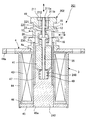
次に、本発明の第2の実施の形態について説明する。図4は本実施の形態の膨張弁の構成を表す断面図である。尚、本実施の形態において上記第1の実施の形態とほぼ同様の構成部分については必要に応じて同一の符号を付す等して、その説明を省略する。
Moreover, the
[Second Embodiment]
Next, a second embodiment of the present invention will be described. FIG. 4 is a cross-sectional view illustrating the configuration of the expansion valve according to the present embodiment. In the present embodiment, components that are substantially the same as those in the first embodiment are denoted by the same reference numerals as necessary, and description thereof is omitted.
図4に示すように、膨張弁201においては、コア242の収容溝248に図2で示したような軸線方向に沿った嵌合溝42aは設けられていない。また、軸状部材230は、その弁座31とは反対側の端部が収容溝248に当接して係止されており、その軸線方向に規制されている。
As shown in FIG. 4, in the
また、弁本体202には、軸状部材230の弁座31側の端面に当接する長尺状の押圧部材220と、ボディ10の端部開口部を閉じるように圧入された円板状のストッパ211とが設けられている。
The
ストッパ211の中央には、これを軸線方向に貫通する挿通孔211aが設けられ、さらにその挿通孔211aの周囲に、挿通孔211aに平行にストッパ211を貫通する複数の連通孔211bが設けられている。冷媒は、この連通孔211bを通って流通できるようになっている。
In the center of the
また、押圧部材220には、その軸線方向の中央部に半径方向外向きに延出するフランジ部221が設けられ、その軸状部材230とは反対側の端部が、ストッパ211の挿通孔211aに挿通されている。ストッパ211と押圧部材220との間には、押圧部材220を軸状部材230側に付勢する圧縮コイルスプリング212が介装されている。このため、軸状部材230は、その両端が押圧部材220及びコア242のそれぞれに当接して、その軸線方向に規制されているが、プランジャ41の挿通孔55との間にクリアランスがあるため、軸線方向と直角な方向には所定量変位することができる。
Further, the pressing
尚、本実施の形態においても、開弁時における弁部22と弁座12との間隙により形成される流路断面と、弁部23と弁座31との間隙により形成される流路断面とが、ほぼ同じ大きさになるように、各弁部及び各弁座の大きさ及び形状が設定されて構成されている。
Also in the present embodiment, the flow path cross section formed by the gap between the
以上に説明した膨張弁201においても、弁部22及び弁部23が、弁座12及び弁座31のそれぞれにほぼ同時に着脱するように構成されている。このため、第1の実施の形態と同様の効果を得ることができる。また、この膨張弁201も双方向膨張弁として機能することができる。
Also in the
また、軸状部材30がその軸線方向と直角な方向には所定量変位することができるため、例えば仮に弁体20及びプランジャ41のいずれかに微妙な加工誤差や組付誤差等があり、二つの弁部22,23の軸線がずれていたとしても、軸状部材230は、弁部23が弁座31に着座するように動作する。その結果、2つの弁部22,23を対応する各弁座12,31に対して同時に着脱させることができる。
Further, since the shaft-shaped
[第3の実施の形態]
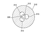
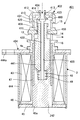
次に、本発明の第3の実施の形態について説明する。図5は本実施の形態の膨張弁の構成を表す断面図であり、図6は図5のA−A矢視断面図である。尚、本実施の形態において上記第1の実施の形態又は第2の実施の形態とほぼ同様の構成部分については必要に応じて同一の符号を付す等して、その説明を省略する。
[Third Embodiment]
Next, a third embodiment of the present invention will be described. FIG. 5 is a cross-sectional view showing the configuration of the expansion valve of the present embodiment, and FIG. 6 is a cross-sectional view taken along the line AA in FIG. In the present embodiment, the same components as those in the first embodiment or the second embodiment are denoted by the same reference numerals as necessary, and the description thereof is omitted.
図5に示すように、膨張弁301においては、プランジャ341は、図2で示したような軸線方向に沿った挿通孔55を備えておらず、中実状に形成されている。
また、軸状部材330は、その下端が半径方向外向きに延出したフランジ状になっており、その先端に向かって外径が小さくなるテーパ状に形成されている。そして、このテーパ部が、弁部23が着座する弁座331を構成している。この軸状部材330は、弁部22と、この弁部22が着座する弁座12を規定する弁孔312を挿通しており、その弁座331とは反対側の他端は、弁本体302のボディ310を軸方向に貫通する嵌合孔311に圧入されて固定されている。
As shown in FIG. 5, in the
Further, the shaft-
また、図6に示すように、ボディ310には、これを軸状部材330の周囲で軸線に平行に貫通する3つの連通孔313が形成されており、弁孔312に連通している。冷媒は、この連通孔313及び弁孔312を通って流通できるようになっている。
Further, as shown in FIG. 6, the
尚、本実施の形態においても、開弁時における弁部22と弁座12との間隙により形成される流路断面と、弁部23と弁座331との間隙により形成される流路断面とがほぼ同じ大きさになるように、各弁部及び各弁座の大きさ及び形状が設定されて構成されている。
Also in the present embodiment, the flow path cross section formed by the gap between the
以上に説明した膨張弁301においても、弁部22及び弁部23が、弁座12及び弁座331のそれぞれにほぼ同時に着脱するように構成されている。このため、第1の実施の形態と同様の効果を得ることができる。また、この膨張弁301も双方向膨張弁として機能することができる。
Also in the
[第4の実施の形態]
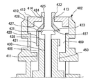
次に、本発明の第4の実施の形態について説明する。図7は本実施の形態の膨張弁の構成を表す断面図であり、図8はその弁本体の構成を表す拡大図である。尚、本実施の形態において上記第1の実施の形態又は第2の実施の形態とほぼ同様の構成部分については必要に応じて同一の符号を付す等して、その説明を省略する。
[Fourth Embodiment]
Next, a fourth embodiment of the present invention will be described. FIG. 7 is a cross-sectional view showing the configuration of the expansion valve of the present embodiment, and FIG. 8 is an enlarged view showing the configuration of the valve body. In the present embodiment, the same components as those in the first embodiment or the second embodiment are denoted by the same reference numerals as necessary, and the description thereof is omitted.
図7に示すように、膨張弁401においては、弁本体402のボディ410内に狭小化した固定の流路断面を有する絞り流路450が設けられている。すなわち、ボディ410の軸線方向の中央よりの位置において、半径方向内向きに延出するフランジ部411が設けられ、このフランジ部411により形成される円孔と、この円孔を貫通して延びるプランジャ441の弁体形成部456との間隙によって絞り流路450が形成されている。
As shown in FIG. 7, the
また、プランジャ441を軸線方向に貫通して設けられた挿通孔455には、長尺状の軸状部材430が所定のクリアランスをもって挿通されており、その先端部に形成された弁座431を覆うように、弁体420が弁体形成部456に対して圧入により固定されている。また、ボディ410の端部開口部を閉じるように円板状のストッパ412が圧入され、このストッパ412の中央を軸線方向に貫通して設けられた弁孔413に弁体420の先端部が挿通されている。
In addition, a long shaft-
尚、図7と図2とを比較すると、図7の右側においては、ヨーク444のフランジ部444aとプレート404とを貫通してねじ63を挿通する挿通孔が見られないが、これは冷媒流路71との位置関係により、当該挿通孔の位置が図2とは異なっているに過ぎない。つまり、当該挿通孔は軸線を中心とする周方向の異なる位置に形成されている。
7 and 2 are compared, on the right side of FIG. 7, there is no insertion hole through which the
図8に示すように、弁体420は、弁体形成部456に圧入される筒状の第1部材421の先端に、筒状の第2部材422を嵌入して構成されている。第1部材421は、弁体形成部456の外径とほぼ等しい内径を有する円筒状の本体を備え、その弁体形成部456とは反対側の端部が先端に向かって縮径するテーパ形状となっている。このテーパ部の内周の基端側には、半径方向内向きに突出した弁部423が形成されている。また、第2部材422は、その第1部材421とは反対側の端部がストッパ412の弁孔413を貫通しており、ストッパ412との間隙により冷媒流路が形成されるようになっている。この第2部材422の先端部には、その先端側に向かって拡径するテーパ部が設けられており、このテーパ部により弁部424が構成されている。膨張弁401においては、第1部材421の側壁に内外を連通させて冷媒を下流側に流すための連通孔457が設けられている。上述した軸状部材430は、弁座431の位置が、弁体420との関係で2つの弁部424,423がそれぞれ各弁座414,431に同時に着脱できるような位置に設定されている。また、弁部424が着座したときの有効受圧面積(つまり弁孔413の流路断面積)と、弁部423が着座したときの有効受圧面積(つまり弁部423の開口端縁により囲まれる流路断面積)とが等しく構成されている。
As shown in FIG. 8, the
また、弁体420にも圧力キャンセル構造が設けられている。すなわち、上流側から弁体420に導入された高圧冷媒に対して、第2部材422の端面425によって閉弁用受圧面が形成される一方、第1部材421と第2部材422との接続部の内側に形成されるテーパ面426によって開弁用受圧面が形成されている。また、弁部423を通過して減圧された冷媒に対して、第1部材421における弁部423近傍の下流側対向面427によって開弁用受圧面が形成される一方、弁体形成部456の端面428によって閉弁用受圧面が形成されている。これにより、弁体420に付与される冷媒圧力の一部がキャンセルされるようになっている。
Further, the
また、ストッパ412は、弁孔413を規定する開口端縁により、弁部423を着脱させることが可能な弁座414が形成されている。また、ストッパ412の下端側納周縁は拡径されており、第1部材421のテーパ部との間に冷媒流路を形成できるように構成されている。
Further, the
尚、本実施の形態においても、開弁時における弁部424と弁座414との間隙により形成される流路断面と、弁部423と弁座431との間隙により形成される流路断面とが、ほぼ同じ大きさになるように、各弁部及び各弁座の大きさ及び形状が設定されて構成されている。
Also in the present embodiment, the flow path cross section formed by the gap between the
次に、図8を参照しつつ、膨張弁401の動作について説明する。
まず、電磁コイル43に電流が供給されていないときには、プランジャ441は圧縮コイルスプリング49によって上流側に付勢されているため、弁部424,423は弁座414,431から離間しており、膨張弁401は開弁状態にある。
Next, the operation of the
First, when no current is supplied to the
そして、電磁コイル43に電流iが供給されると、その電流値に応じた大きさの電磁力が発生してプランジャ441がコア242に吸引される。これにより、圧縮コイルスプリング49の付勢力に抗して弁体420を着座させる方向の力が発生する。その結果、弁体420は、その電磁力と圧縮コイルスプリング49の荷重とがバランスした位置で静止し、各弁部と各弁座との間に所定の流路断面を形成する。
When the current i is supplied to the
この状態で上流側から高圧の冷媒が導入されると、その冷媒は、弁部424と弁座414との間隙、弁部423と弁座431との間隙を通って減圧されて下流側に流れ、さらに絞り流路450を通過することにより断熱膨張し、連通孔14を介して冷媒流路71の下流側へと流れる。このとき、上述したキャンセル構造により、弁体420ひいてはプランジャ441に付与される冷媒圧力の一部がキャンセルされている。
In this state, when a high-pressure refrigerant is introduced from the upstream side, the refrigerant is decompressed through the gap between the
ここで、上流側から導入されて各弁体と各弁座との間隙を通過する前の冷媒の入口圧力をP1、各弁体と各弁座との間隙を通過することによって減圧された中間領域460の圧力をP2、絞り流路450を通過することによってさらに減圧された冷媒の出口圧力をP3とし、弁部424が着座したときの有効受圧面積(つまり弁孔413の流路断面積)をA、弁部423が着座したときの有効受圧面積(つまり弁部423の開口端縁により囲まれる流路断面積)をB、絞り流路450の流路断面積をCとすると、膨張弁401を流れる冷媒の流量Gfは、
Gf=KC(P2−P3) ・・・(6)
で表される。尚、この式で、Kは流量係数である。
Here, the inlet pressure of the refrigerant introduced from the upstream side and passing through the gap between each valve body and each valve seat is P1, and the intermediate pressure reduced by passing through the gap between each valve body and each valve seat The pressure of the
Gf = KC (P2-P3) (6)
It is represented by In this equation, K is a flow coefficient.
一方、弁体420ひいてはプランジャ441に作用する力は、電流iによって発生する電磁力をf(i)、圧縮コイルスプリング49による上流側方向の荷重をfs、電流iのときの各弁部と各弁座との間隙により形成される流路断面積をs(i)とすると、上向きと下向きの力関係は、
((A−s(i))−(B−s(i)))(P1−P2)
+ D(P2−P3) =fs−f(i) ・・・(7)
となり、本実施の形態においてA=Bであることを考慮すると、(6)式及び(7)式から、冷媒の流量Gfは、
Gf=(KC/D)(fs−f(i)) ・・・(8)
となる。
On the other hand, the force acting on the
((A-s (i))-(Bs (i))) (P1-P2)
+ D (P2-P3) = fs-f (i) (7)
Thus, considering that A = B in the present embodiment, from the equations (6) and (7), the flow rate Gf of the refrigerant is
Gf = (KC / D) (fs−f (i)) (8)
It becomes.
すなわち、電流iによって変化する流路断面積s(i)の影響がなくなる。そして、この(8)式の右辺において、電磁力f(i)以外のパラメータは、実質的に固定値であり、絞り流路450の前後差圧(P2−P3)が一定に保持される原理については上記第1の実施の形態で述べたのと同様であるため、流量Gfは、電磁コイル43に供給される電流iに比例した一定の流量で流れることになる。すなわち、膨張弁401が定流量弁として構成される。
That is, the influence of the channel cross-sectional area s (i) that changes with the current i is eliminated. In the right side of the equation (8), parameters other than the electromagnetic force f (i) are substantially fixed values, and the principle that the differential pressure (P2−P3) across the
以上に説明した膨張弁401においても、弁部424及び弁部423が、弁座414及び弁座431のそれぞれにほぼ同時に着脱するように構成されている。このため、第1の実施の形態と同様の効果を得ることができる。
Also in the
[第5の実施の形態]
次に、本発明の第5の実施の形態について説明する。図9は本実施の形態の膨張弁の構成を表す断面図である。尚、本実施の形態において上記第1の実施の形態〜第4の実施の形態とほぼ同様の構成部分については必要に応じて同一の符号を付す等して、その説明を省略する。
[Fifth Embodiment]
Next, a fifth embodiment of the present invention will be described. FIG. 9 is a cross-sectional view showing the configuration of the expansion valve of the present embodiment. In the present embodiment, the same components as those in the first to fourth embodiments are denoted by the same reference numerals as necessary, and the description thereof is omitted.
図9に示すように、膨張弁501においては、上述した第4の実施の形態とは冷媒の流れ方向が逆となっており、絞り流路550が弁体20の上流側に配置されている。また、弁本体502のボディ510の端部開口部を閉じるように円板状のストッパ540が圧入され、このストッパ540の中央を軸線方向に貫通して弁孔511が形成されている。そして、この弁孔511の弁体20側の開口部の周端縁によって、弁体20の先端に設けられた弁部22が着脱可能な弁座12が形成されている。
As shown in FIG. 9, in the
また、コア542の収容溝48の底部には、プランジャ541から離れる方向に段階的に縮径する段付溝543が形成されており、この段付溝543の上端部には、リング状のストッパ部材544が嵌合されている。一方、軸状部材530の下端部には、Cリング545が嵌合しており、このCリング545の位置でストッパ部材544に上方への動きを規制されている。軸状部材530は、弁座31の位置が、弁体20との関係で2つの弁部22,23がそれぞれ各弁座12,31に同時に着脱できるような位置に設定されている。
Further, a stepped
冷媒流路71の上流側から流入した冷媒は、弁体20の開弁時には、絞り流路550を通って断熱膨張した後に、弁部23と弁座31との間隙及び弁部22と弁座12との間隙を通ってさらに減圧されて下流側に導出される。
When the
尚、本実施の形態においても、開弁時における弁部22と弁座12との間隙により形成される流路断面と、弁部23と弁座31との間隙により形成される流路断面とが、ほぼ同じ大きさになるように、各弁部及び各弁座の大きさ及び形状が設定されて構成されている。
Also in the present embodiment, the flow path cross section formed by the gap between the
以上に説明した膨張弁501においても、弁部22及び弁部23が、弁座12及び弁座31のそれぞれにほぼ同時に着脱するように構成されている。このため、第1の実施の形態と同様の効果を得ることができる。
Also in the
[第6の実施の形態]
次に、本発明の第6の実施の形態について説明する。図10は本実施の形態の膨張弁の構成を表す断面図である。尚、本実施の形態の膨張弁は、冷凍サイクルの配管の途中に接続されるパイプ一体型の膨張弁として構成されたものであり、その内部の弁体等の構成については上述した第2の実施の形態とほぼ同様のものを採用している。このため、第2の実施の形態と同様の構成部分については同一の符号を付す等してその説明を省略する。
[Sixth Embodiment]
Next, a sixth embodiment of the present invention will be described. FIG. 10 is a cross-sectional view showing the configuration of the expansion valve of the present embodiment. The expansion valve of the present embodiment is configured as a pipe-integrated expansion valve connected in the middle of the piping of the refrigeration cycle, and the configuration of the internal valve body and the like is the above-described second. The thing similar to embodiment is employ | adopted. For this reason, the same components as those of the second embodiment are denoted by the same reference numerals and the description thereof is omitted.
膨張弁601は、そのボディ602を両端が開口した円筒状のパイプで構成しており、そのボディ602の内部に、弁体20を固定したプランジャ41,コア642,軸状部材230,押圧部材220,ストッパ610を収容している。そして、このボディ602を外側から取り囲むように、ソレノイド603を構成する電磁コイル43や筒状のヨーク644が周設されている。また、軸状部材230は、弁座31の位置が、弁体20との関係で2つの弁部22,23がそれぞれ各弁座12,31に同時に着脱できるような位置に設定されている。
The
尚、本実施の形態においても、開弁時における弁部22と弁座12との間隙により形成される流路断面と、弁部23と弁座31との間隙により形成される流路断面とが、ほぼ同じ大きさになるように、各弁部及び各弁座の大きさ及び形状が設定されて構成されている。
Also in the present embodiment, the flow path cross section formed by the gap between the
以上に説明した膨張弁601においても、弁部22及び弁部23が、弁座12及び弁座31のそれぞれにほぼ同時に着脱するように構成されている。このため、第1の実施の形態と同様の効果を得ることができる。
Also in the
以上、本発明の好適な実施の形態について説明したが、本発明はその特定の実施の形態に限定されるものではなく、本発明の精神の範囲内での変化変形が可能であることはいうまでもない。 The preferred embodiment of the present invention has been described above, but the present invention is not limited to the specific embodiment, and it can be changed and modified within the spirit of the present invention. Not too long.
例えば、上記第1の実施の形態〜第5の実施の形態では、膨張弁のボディが配管本体70に直接固定されるように構成した例を示したが、これらの膨張弁がボディを収容するケーシング等を備えており、配管等に接続されるものであってもよい。
For example, in the first to fifth embodiments, an example in which the body of the expansion valve is configured to be directly fixed to the
また、上記各実施の形態では、弁部及び弁体をそれぞれ2段で構成した例を示したが、弁部及び弁座は必ずしも2段に限られず、各弁部のリフト時における有効受圧面積が変化することによる流体圧力の影響の少なくとも一部をキャンセルできれば、それより多くの段数があってもよい。 Moreover, in each said embodiment, although the example which each comprised the valve part and the valve body by 2 steps | paragraphs was shown, the valve part and the valve seat are not necessarily restricted to 2 steps | paragraphs, The effective pressure-receiving area at the time of the lift of each valve part As long as at least a part of the influence of the fluid pressure due to the change in the pressure can be canceled, there may be more stages.
また、上記第2の実施の形態においては、軸状部材230と押圧部材220とを別体で構成して空間Sにて当接する構成としたが、これら軸状部材230と押圧部材220とが一体的に構成されていてもよい。このような場合でも、ストッパ211の挿通孔211aと押圧部材220との間に所定のクリアランスを設けておけば、軸状部材30は、弁部23が弁座31に着座するように動作する。その結果、2つの弁部22,23を対応する各弁座12,31に対して同時に着脱させることができる。
Further, in the second embodiment, the shaft-shaped
また、上記各実施の形態では、本発明の流体制御弁を車両用エアコンの冷凍サイクルに設置される膨張弁として構成した例を示したが、膨張弁に限らず、例えば可変容量圧縮機用制御弁やその他の冷媒の流量を制御する制御弁であれば同様に適用することができる。さらに、車両用エアコンの冷凍サイクルに限らず、例えば給湯システム等の制御弁など、上流側から導入された流体の流量を調整して下流側に導出する流体制御弁であれば適用することが可能である。 In each of the above-described embodiments, the example in which the fluid control valve of the present invention is configured as an expansion valve installed in a refrigeration cycle of a vehicle air conditioner has been described. Any control valve that controls the flow rate of a valve or other refrigerant can be applied in the same manner. Furthermore, the present invention is not limited to the refrigeration cycle of a vehicle air conditioner, and can be applied to any fluid control valve that regulates the flow rate of fluid introduced from the upstream side and derives it downstream, such as a control valve for a hot water supply system, for example. It is.
さらに、上記各実施の形態では、ソレノイドにより弁体が電磁駆動される構成について説明したが、ばね等を含む内部の機械的構成と流体圧力により弁体が駆動されるいわゆる機械式の流体制御弁にも適用することが可能である。 Further, in each of the above embodiments, the configuration in which the valve body is electromagnetically driven by the solenoid has been described. However, a so-called mechanical fluid control valve in which the valve body is driven by an internal mechanical configuration including a spring or the like and fluid pressure. It is also possible to apply to.
1,201,301,401,501,601 膨張弁
2,202,302,402,502 弁本体
3,603 ソレノイド
10,310,410,510 ボディ
11,312,413,511 弁孔
12,31,331,414,431 弁座
14 連通孔
20,420 弁体
22,23,423,424 弁部
30,230,330,430,530 軸状部材
41,341,441,541 プランジャ
42,242,542 コア
43 電磁コイル
49 圧縮コイルスプリング
56,456 弁体形成部
70 配管本体
71 冷媒流路
212 圧縮コイルスプリング
220 押圧部材
450,550 絞り流路
1,201,301,401,501,601 Expansion valve 2,202,302,402,502 Valve body 3,603 Solenoid 10,310,410,510 Body 11,312,413,511
Claims (10)
内部に前記流体の流路が形成されたボディと、
前記ボディ内に前記流路に沿って設けられた第1弁座及び第2弁座と、
前記第1弁座及び前記第2弁座のそれぞれにほぼ同時に接離可能な第1弁部及び第2弁部が一体的に設けられ、前記ボディ内で支持されつつ進退し、各弁部の各弁座からのリフト量によって下流側へ流す前記流体の流量を調整する弁体と、
前記弁体の開弁方向に作用する流体圧力を受ける開弁用受圧面と、前記弁体の閉弁方向に作用する流体圧力を受ける閉弁用受圧面とからなり、前記弁体に作用する流体圧力の少なくとも一部をキャンセルする圧力キャンセル構造と、
を備えたことを特徴とする流体制御弁。 In the fluid control valve for adjusting the flow rate of the fluid introduced from the upstream side and leading it to the downstream side,
A body in which the fluid flow path is formed;
A first valve seat and a second valve seat provided along the flow path in the body;
A first valve portion and a second valve portion that can be brought into and out of contact with each of the first valve seat and the second valve seat are provided integrally, and are advanced and retracted while being supported in the body. A valve body for adjusting the flow rate of the fluid flowing downstream by the lift amount from each valve seat;
A valve opening pressure receiving surface that receives a fluid pressure acting in the valve opening direction of the valve body and a valve closing pressure receiving surface that receives a fluid pressure acting in the valve closing direction of the valve body and acts on the valve body A pressure canceling structure for canceling at least part of the fluid pressure;
A fluid control valve comprising:
前記電磁コイルに供給される電流値に応じて前記弁体のリフト量を制御し、上流側から導入された流体の流量を調整して下流側に導出する電磁弁として構成されたことを特徴とする請求項1記載の流体制御弁。 A core fixed to the body; a plunger capable of advancing and retracting integrally with the valve body in the body by fixing the valve body; and a magnet including the plunger and the core by a supply current from the outside. A solenoid composed of an electromagnetic coil for generating a circuit;
It is configured as an electromagnetic valve that controls the lift amount of the valve body in accordance with the current value supplied to the electromagnetic coil, adjusts the flow rate of the fluid introduced from the upstream side, and leads it to the downstream side. The fluid control valve according to claim 1.
前記第1弁部及び前記第2弁部の一方が、前記本体の前記導入路側又は前記導出路側の端部により形成される一方、前記第1弁部及び前記第2弁部の他方が、前記拡管部の前記導入路側又は前記導出路側の段部によって形成され、
前記第1弁座及び前記第2弁座の一方が、前記ボディの内部に設けられた段部により構成される一方、前記第1弁座及び前記第2弁座の他方が、前記拡管部に部分的に内挿された軸状部材の部分により形成されたことを特徴とする請求項3記載の流体制御弁。 The valve body includes a main body having an introduction path for introducing the fluid, a lead-out path for deriving the fluid, and a pipe expanding portion provided between the introduction path and the lead-out path,
One of the first valve part and the second valve part is formed by an end part of the main body on the introduction path side or the lead-out path side, while the other of the first valve part and the second valve part is the It is formed by the step part on the introduction path side or the lead-out path side of the expansion part,
One of the first valve seat and the second valve seat is configured by a step portion provided inside the body, while the other of the first valve seat and the second valve seat is the tube expansion portion. 4. The fluid control valve according to claim 3, wherein the fluid control valve is formed by a portion of a shaft-like member partially inserted.
前記押圧部材を前記コア側に付勢する付勢手段と、
を備え、
前記軸状部材は、軸線方向の両端が前記押圧部材及び前記コアのそれぞれに当接して、その軸線方向に規制される一方、その軸線方向と直角な方向には所定量動作可能に構成されていることを特徴とする請求項5記載の流体制御弁。 A pressing member supported in the body and capable of contacting the shaft-like member from a side opposite to the core;
Biasing means for biasing the pressing member toward the core;
With
The axial member is configured such that both ends in the axial direction abut against each of the pressing member and the core and are regulated in the axial direction, while being operable in a predetermined amount in a direction perpendicular to the axial direction. 6. The fluid control valve according to claim 5, wherein:
The fluid control valve according to claim 3, wherein the fluid control valve functions as a bidirectional control valve capable of flowing the fluid bidirectionally with respect to the valve body.
Priority Applications (3)
| Application Number | Priority Date | Filing Date | Title |
|---|---|---|---|
| JP2004117644A JP2005299811A (en) | 2004-04-13 | 2004-04-13 | Fluid control valve |
| US11/103,534 US7118088B2 (en) | 2004-04-13 | 2005-04-12 | Fluid control valve |
| EP20050007974 EP1586835A3 (en) | 2004-04-13 | 2005-04-12 | Fluid control valve |
Applications Claiming Priority (1)
| Application Number | Priority Date | Filing Date | Title |
|---|---|---|---|
| JP2004117644A JP2005299811A (en) | 2004-04-13 | 2004-04-13 | Fluid control valve |
Publications (1)
| Publication Number | Publication Date |
|---|---|
| JP2005299811A true JP2005299811A (en) | 2005-10-27 |
Family
ID=34935035
Family Applications (1)
| Application Number | Title | Priority Date | Filing Date |
|---|---|---|---|
| JP2004117644A Pending JP2005299811A (en) | 2004-04-13 | 2004-04-13 | Fluid control valve |
Country Status (3)
| Country | Link |
|---|---|
| US (1) | US7118088B2 (en) |
| EP (1) | EP1586835A3 (en) |
| JP (1) | JP2005299811A (en) |
Families Citing this family (13)
| Publication number | Priority date | Publication date | Assignee | Title |
|---|---|---|---|---|
| FR2858374B1 (en) * | 2003-07-29 | 2007-10-26 | Delphi Tech Inc | ELECTROVALVE, METHOD FOR ASSEMBLING A SOLENOID ON SAID ELECTROVALVE, AND METHOD FOR DISASSEMBLING SOLENOID OF SAID ELECTROVALVE |
| JP2006242413A (en) * | 2005-03-01 | 2006-09-14 | Tgk Co Ltd | Constant flow rate expansion valve |
| US8443839B2 (en) * | 2009-10-20 | 2013-05-21 | Eaton Corporation | Fluid-biased hydraulic control valve with armature piston |
| JP5572809B2 (en) * | 2010-09-30 | 2014-08-20 | 株式会社テージーケー | Control valve |
| CN103453169A (en) * | 2013-05-27 | 2013-12-18 | 大连博锐特科技工程有限公司 | Internal safety stop valve device for oil storage pipeline |
| CN103899765A (en) * | 2014-04-02 | 2014-07-02 | 苏州沃特节水产品有限公司 | Valve block for water inlet valve of water tank |
| DE102017122624B4 (en) * | 2017-09-28 | 2019-08-14 | Pierburg Gmbh | Expansion valve for a refrigeration or air conditioning cycle |
| EP3569904B1 (en) * | 2018-05-18 | 2020-11-04 | Fas Medic S.A. | Valve assembly |
| US11027909B2 (en) | 2018-08-15 | 2021-06-08 | Gpcp Ip Holdings Llc | Automated flowable material dispensers and related methods for dispensing flowable material |
| RU2713305C9 (en) * | 2019-04-02 | 2020-08-13 | Акционерное общество "Уральский электромеханический завод" | Electromagnetic valve |
| US12064063B2 (en) | 2019-09-23 | 2024-08-20 | Gpcp Ip Holdings Llc | Automated toilet seat cover dispenser |
| WO2021204389A1 (en) * | 2020-04-09 | 2021-10-14 | Pierburg Gmbh | Expansion valve for a refrigeration or air-conditioning circuit, and method for actuating the expansion valve |
| CN114607782B (en) * | 2022-01-26 | 2023-01-31 | 广东威灵电机制造有限公司 | Electronic expansion valve and refrigeration equipment |
Family Cites Families (19)
| Publication number | Priority date | Publication date | Assignee | Title |
|---|---|---|---|---|
| US3053271A (en) * | 1960-06-22 | 1962-09-11 | Jr Eugene C Crittenden | Sampling pressure regulator |
| SE332217B (en) * | 1966-10-28 | 1971-02-01 | Asea Ab | |
| CA1021225A (en) * | 1974-06-28 | 1977-11-22 | General Signal Corporation | Quick-acting valve assembly |
| DE2645802C2 (en) * | 1976-10-09 | 1985-10-03 | Fritz 7118 Ingelfingen Müller | Damping device for a valve |
| JPS589307B2 (en) * | 1978-08-23 | 1983-02-19 | 株式会社日立製作所 | Proportional solenoid valve |
| US4338966A (en) * | 1979-02-09 | 1982-07-13 | Chrysler Corporation | Direct solenoid operated directional control valve |
| JPS579380A (en) * | 1980-06-20 | 1982-01-18 | Hitachi Ltd | Proportional control valve |
| JPS599373A (en) * | 1982-07-09 | 1984-01-18 | Hitachi Ltd | Flow rate controller |
| DE4019073A1 (en) * | 1990-06-15 | 1991-12-19 | Rexroth Pneumatik Mannesmann | VALVE DEVICE |
| DE4120292C2 (en) * | 1991-06-17 | 1994-06-09 | Mannesmann Ag | Double-seat valve actuated by an electromagnet |
| DE4129755C2 (en) * | 1991-09-04 | 1994-09-29 | Mannesmann Ag | Double seat valve arrangement |
| JP3050690B2 (en) * | 1992-03-09 | 2000-06-12 | 株式会社デンソー | Electromagnetic drive control valve |
| US5263514A (en) * | 1992-09-28 | 1993-11-23 | Delavan Inc | Boom control valve |
| US5765513A (en) * | 1996-11-12 | 1998-06-16 | Ford Global Technologies, Inc. | Electromechanically actuated valve |
| TW506498U (en) * | 1996-12-01 | 2002-10-11 | Tadahiro Ohmi | Fluid control valve and fluid supply/exhaust system |
| DE19650445C1 (en) * | 1996-12-05 | 1998-06-04 | Jci Regelungstechnik Gmbh | Gas control for gas=blast burner in heating plant |
| FR2817605B1 (en) * | 2000-12-01 | 2005-05-20 | Eaton Corp | PROPORTIONAL SOLENOID VALVE FOR MOTOR COOLANT LIQUID CIRCUIT |
| DE10063710A1 (en) * | 2000-12-20 | 2002-07-04 | Wabco Gmbh & Co Ohg | valve means |
| IL141989A0 (en) * | 2001-03-12 | 2002-03-10 | El Far Electronics Ltd | Armature for solenoid devices such as valves |
-
2004
- 2004-04-13 JP JP2004117644A patent/JP2005299811A/en active Pending
-
2005
- 2005-04-12 US US11/103,534 patent/US7118088B2/en not_active Expired - Fee Related
- 2005-04-12 EP EP20050007974 patent/EP1586835A3/en not_active Withdrawn
Also Published As
| Publication number | Publication date |
|---|---|
| US7118088B2 (en) | 2006-10-10 |
| EP1586835A3 (en) | 2007-08-22 |
| EP1586835A2 (en) | 2005-10-19 |
| US20050224740A1 (en) | 2005-10-13 |
Similar Documents
| Publication | Publication Date | Title |
|---|---|---|
| JP5421059B2 (en) | solenoid valve | |
| JP4805320B2 (en) | Solenoid open / close valve | |
| CN102834656B (en) | Balance poppet type solenoid valve | |
| KR101955038B1 (en) | Control valve | |
| US7106158B2 (en) | Solenoid-actuated air valve | |
| JP2005299811A (en) | Fluid control valve | |
| US4304264A (en) | Solenoid actuated valve | |
| US9523441B2 (en) | Electromagnetic valve | |
| JP5664873B2 (en) | Valve for supplying fluid | |
| EP2853795B1 (en) | Electromagnetic valve | |
| JP2004100722A (en) | Proportional valve | |
| JP2006242413A (en) | Constant flow rate expansion valve | |
| CA2619394C (en) | Solenoid isolation valve | |
| JP5982703B2 (en) | Pressure reducing valve | |
| JP5722164B2 (en) | Decompressor | |
| JP2005083566A (en) | Constant flow rate expansion valve | |
| JP2019124240A (en) | Valve device | |
| JP5712092B2 (en) | Valve with pilot function | |
| JP2003065633A (en) | Solenoid valve integrated expansion valve | |
| JP7664617B2 (en) | Expansion valve | |
| JP2004053192A (en) | Expansion valve of constant flow rate | |
| JP6218233B2 (en) | Pressure reducing valve | |
| CN103688091A (en) | Valve module | |
| JP2004044673A (en) | Solenoid control valve | |
| CN120322636A (en) | Solenoid valve and assembly method of solenoid valve |
Legal Events
| Date | Code | Title | Description |
|---|---|---|---|
| A621 | Written request for application examination |
Free format text: JAPANESE INTERMEDIATE CODE: A621 Effective date: 20061130 |
|
| A977 | Report on retrieval |
Free format text: JAPANESE INTERMEDIATE CODE: A971007 Effective date: 20090331 |
|
| A131 | Notification of reasons for refusal |
Free format text: JAPANESE INTERMEDIATE CODE: A131 Effective date: 20090616 |
|
| A02 | Decision of refusal |
Free format text: JAPANESE INTERMEDIATE CODE: A02 Effective date: 20091020 |