DE19906552B4 - Standpipe cover for attachment in the transition area from the downpipe to the standpipe - Google Patents
Standpipe cover for attachment in the transition area from the downpipe to the standpipe Download PDFInfo
- Publication number
- DE19906552B4 DE19906552B4 DE19906552A DE19906552A DE19906552B4 DE 19906552 B4 DE19906552 B4 DE 19906552B4 DE 19906552 A DE19906552 A DE 19906552A DE 19906552 A DE19906552 A DE 19906552A DE 19906552 B4 DE19906552 B4 DE 19906552B4
- Authority
- DE
- Germany
- Prior art keywords
- standpipe
- downpipe
- bead
- cover
- sleeve
- Prior art date
- Legal status (The legal status is an assumption and is not a legal conclusion. Google has not performed a legal analysis and makes no representation as to the accuracy of the status listed.)
- Expired - Fee Related
Links
Classifications
-
- E—FIXED CONSTRUCTIONS
- E04—BUILDING
- E04D—ROOF COVERINGS; SKY-LIGHTS; GUTTERS; ROOF-WORKING TOOLS
- E04D13/00—Special arrangements or devices in connection with roof coverings; Protection against birds; Roof drainage ; Sky-lights
- E04D13/04—Roof drainage; Drainage fittings in flat roofs, balconies or the like
- E04D13/08—Down pipes; Special clamping means therefor
Landscapes
- Engineering & Computer Science (AREA)
- Architecture (AREA)
- Civil Engineering (AREA)
- Structural Engineering (AREA)
- Sink And Installation For Waste Water (AREA)
- Sewage (AREA)
- Pressure Vessels And Lids Thereof (AREA)
- Protection Of Pipes Against Damage, Friction, And Corrosion (AREA)
Abstract
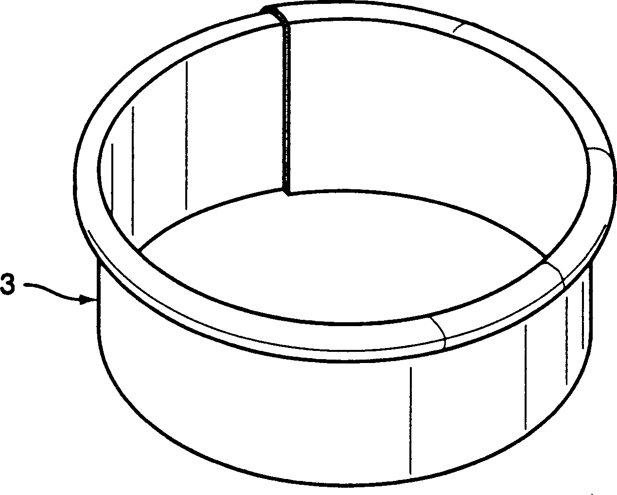
Standrohrabdeckung zur Anbringung im Übergangsbereich vom Regenfallrohr (1) zum Standrohr (2), bestehend aus einem das Regenfallrohr (1) umgreifenden, hülsenförmigen Teil (4), dadurch gekennzeichnet, daß das hülsenförmige Teil (4) als offener, einen radialen Trennspalt (5) aufweisender zylindrischer Ring ausgebildet ist, der an seinem einen Ende einen radial nach außen sich erstreckenden Wulst (6) zum Überkragen des Standrohrs (2) aufweist, wobei das dem Wulst (6) abgewandte Ende zwischen das Regenfallrohr (1) und das Standrohr (2) greift.Standpipe cover for attachment in the transition area from the downpipe (1) to the standpipe (2), consisting of a the Rain tube (1) embracing, sleeve-shaped part (4), characterized that this sleeve-shaped part (4) as an open, a radial separating gap (5) exhibiting cylindrical Ring is formed, which at its one end a radially to Outside extending bead (6) for overhanging the standpipe (2) , wherein the bead (6) facing away from the end of the downpipe (1) and the standpipe (2) engages.
Description
Die Erfindung betrifft eine Standrohrabdeckung zur Anbringung im Übergangsbereich vom Regenfallrohr zum Standrohr, bestehend aus einem das Regenfallrohr umgreifenden, hülsenförmigen Teil.The The invention relates to a standpipe cover for attachment in the transition region from the downpipe to the standpipe, consisting of a downpipe encompassing, sleeve-shaped part.
Bekannte Standrohrabdeckungen dieser Art bestehen üblicherweise aus einem rohrförmigen Teil, das mit seinem einen Ende das Regenfallrohr umgreift und mit seinem anderen, dem gegenüber aufgeweiteten Ende das Standrohr übergreift. Es handelt sich hierbei um in sich geschlossene, ausgestanzte Ringe, die sich an die einzelnen Fallrohre üblicherweise nicht optimal anpassen, da diese normalerweise konisch ausgebildet sind, also ein enges und ein weites Ende haben, um ineinander steckbar zu sein.Known Stand pipe covers of this type usually consist of a tubular part, the with one end around the rainwater pipe and with his other, opposite flared end of the standpipe overlaps. It is about here around self-contained, punched-out rings that adhere to the individual downpipes usually not optimally adapt, as these are usually conical are, so have a narrow and a long end to be plugged into each other.
Da auch die Standrohre je nach Material und Hersteller Differenzen in ihrer Wandstärke und im Durchmesser aufweisen, passen die bekannten Standrohrabdeckungen in den seltensten Fällen. Da sie in der Regel eher zu groß angefertigt werden, haben sie keinen festen Sitz, wackeln also und hängen oftmals schief auf dem Standrohr. Sind sie dagegen zu eng, müssen sie vor der Montage aufgeweitet werden.There also the stanchions, depending on the material and manufacturer differences in their wall thickness and in diameter, fit the known standpipe covers In the most rare events. Because they are usually made rather large they do not have a tight fit, so they wobble and hang often crooked on the standpipe. If they are too tight, they have to be widened before mounting.
Der Erfindung liegt die Aufgabe zugrunde, eine Standrohrabdeckung der eingangs genannten Art zu schaffen, die sich an die jeweils örtlichen Verhältnisse optimal anpaßt, einen festen Sitz bietet und darüber hinaus eine formschöne Abdeckung des Standrohres gewährleistet.Of the Invention is the object of a standpipe cover the to create the type mentioned above, which is in each case the local conditions optimally adapts, offers a tight fit and above a shapely one Cover of the standpipe guaranteed.
Diese Aufgabe wird nach der Erfindung dadurch gelöst, daß das hülsenförmige Teil als offener, einen radialen Trennspalt aufweisender zylindrischer Ring ausgebildet ist, der an seinem einen Ende einen radial nach außen sich erstreckenden Wulst zum Überkragen des Standrohrs aufweist, wobei das dem Wulst abgewandte Ende zwischen das Regenfallrohr und das Standrohr greift.These The object is achieved according to the invention in that the sleeve-shaped part as an open, a formed radial separating gap exhibiting cylindrical ring is that at its one end a radially outward extending bead to overhang of the standpipe, wherein the bead facing away from the end the downpipe and the standpipe grip.
Der durch die Erfindung erreichte Vorteil besteht im wesentlichen darin, daß die Standrohrabdeckung durch den vorhandenen radialen Trennspalt ohne zusätzliche Nachbearbeitung sich optimal an das Regenfallrohr anpaßt, wobei darüber hinaus lediglich der die Stirnseite des Standrohres überdeckende Wulst sichtbar ist, woraus sich eine unauffällige, gleichwohl formschöne Abdeckung ergibt, die darüber hinaus auch eine saubere Abdeckung eines unschön oder schräg abgesägten Rohres ermöglicht.Of the The advantage achieved by the invention consists essentially in that the Stand pipe cover by the existing radial separating gap without additional Post-processing optimally adapts to the downpipe, wherein about that In addition, only the front side of the standpipe overlapping Bead is visible, resulting in a discreet, yet attractive cover that's about it In addition, a clean cover of an unsightly or sloping sawn pipe allows.
In bevorzugter Ausführungsform ist der Ring federnd ausgebildet und überlappt im Bereich des radialen Trennspaltes. Dadurch ist eine feste Anlage der Standrohrabdeckung am Regenfallrohr gewährleistet, wobei im übrigen durch die stramme Anlage am Regenfallrohr das Einschieben in das Standrohr erleichtert wird.In preferred embodiment the ring is resilient and overlaps in the radial Separating gap. This is a solid investment the standpipe cover guaranteed at the downpipe, while otherwise through the tight attachment to the downpipe insertion into the Standpipe is facilitated.
Der Wulst weist in bevorzugter Ausführungsform der Erfindung eine kreisbogenförmige Gestalt auf, wodurch eine gute Überdeckung des oberen Endes des Standrohres erreicht wird.Of the Bead points in a preferred embodiment the invention is a circular arc Shape up, creating a good overlap the upper end of the standpipe is reached.
Um im übrigen einen festen Sitz der Standrohrabdeckung auf dem Regenfallrohr sicherzustellen, beträgt die axiale Länge des hülsenförmigen Teils zweckmäßigerweise ein mehrfaches gegenüber der Höhe des Wulstes.Around Furthermore ensure a tight fit of the standpipe cover on the downpipe is the axial length of the sleeve-shaped part expediently a multiple compared to the Height of Bead.
Im folgenden wird die Erfindung an einem in der Zeichnung dargestellten Ausführungsbeispiel näher erläutert; es zeigen:in the Next, the invention will be illustrated on a drawing embodiment explained in more detail; it demonstrate:
Die
in der Zeichnung dargestellte Standrohrabdeckung
Im
einzelnen besteht die Standrohrabdeckung
Der
Ring ist federnd ausgebildet und überlappt im Bereich des radialen
Trennspaltes
Der
Wulst
Um
einen sicheren Halt im Standrohr
Claims (4)
Priority Applications (1)
| Application Number | Priority Date | Filing Date | Title |
|---|---|---|---|
| DE19906552A DE19906552B4 (en) | 1998-03-09 | 1999-02-17 | Standpipe cover for attachment in the transition area from the downpipe to the standpipe |
Applications Claiming Priority (3)
| Application Number | Priority Date | Filing Date | Title |
|---|---|---|---|
| DE29804091U DE29804091U1 (en) | 1998-03-09 | 1998-03-09 | Standpipe cover for attachment in the transition area from the downpipe to the standpipe |
| DE29804091.3 | 1998-03-09 | ||
| DE19906552A DE19906552B4 (en) | 1998-03-09 | 1999-02-17 | Standpipe cover for attachment in the transition area from the downpipe to the standpipe |
Publications (2)
| Publication Number | Publication Date |
|---|---|
| DE19906552A1 DE19906552A1 (en) | 1999-09-16 |
| DE19906552B4 true DE19906552B4 (en) | 2006-03-23 |
Family
ID=8053789
Family Applications (2)
| Application Number | Title | Priority Date | Filing Date |
|---|---|---|---|
| DE29804091U Expired - Lifetime DE29804091U1 (en) | 1998-03-09 | 1998-03-09 | Standpipe cover for attachment in the transition area from the downpipe to the standpipe |
| DE19906552A Expired - Fee Related DE19906552B4 (en) | 1998-03-09 | 1999-02-17 | Standpipe cover for attachment in the transition area from the downpipe to the standpipe |
Family Applications Before (1)
| Application Number | Title | Priority Date | Filing Date |
|---|---|---|---|
| DE29804091U Expired - Lifetime DE29804091U1 (en) | 1998-03-09 | 1998-03-09 | Standpipe cover for attachment in the transition area from the downpipe to the standpipe |
Country Status (1)
| Country | Link |
|---|---|
| DE (2) | DE29804091U1 (en) |
Citations (3)
| Publication number | Priority date | Publication date | Assignee | Title |
|---|---|---|---|---|
| CH240715A (en) * | 1944-06-27 | 1946-01-15 | Hagedorn Hans | Heating device on downpipes of gutters to prevent freezing. |
| DE7002644U (en) * | 1970-01-27 | 1970-07-02 | Klempnereibedarfs Ges Mannigel | CONNECTOR FOR RAINPIPE MADE OF METAL. |
| DE1911159A1 (en) * | 1969-03-05 | 1970-11-26 | Max Huppert | Device on liquid drainage pipes, especially for gutters |
-
1998
- 1998-03-09 DE DE29804091U patent/DE29804091U1/en not_active Expired - Lifetime
-
1999
- 1999-02-17 DE DE19906552A patent/DE19906552B4/en not_active Expired - Fee Related
Patent Citations (3)
| Publication number | Priority date | Publication date | Assignee | Title |
|---|---|---|---|---|
| CH240715A (en) * | 1944-06-27 | 1946-01-15 | Hagedorn Hans | Heating device on downpipes of gutters to prevent freezing. |
| DE1911159A1 (en) * | 1969-03-05 | 1970-11-26 | Max Huppert | Device on liquid drainage pipes, especially for gutters |
| DE7002644U (en) * | 1970-01-27 | 1970-07-02 | Klempnereibedarfs Ges Mannigel | CONNECTOR FOR RAINPIPE MADE OF METAL. |
Also Published As
| Publication number | Publication date |
|---|---|
| DE29804091U1 (en) | 1998-04-23 |
| DE19906552A1 (en) | 1999-09-16 |
Similar Documents
| Publication | Publication Date | Title |
|---|---|---|
| DE19906552B4 (en) | Standpipe cover for attachment in the transition area from the downpipe to the standpipe | |
| DE2312745A1 (en) | FOLDING DOOR MADE OF EXTRUDED PLASTIC | |
| EP0275055A2 (en) | Plastic pipe | |
| EP0591711A1 (en) | Guard device, in particular for a roof gutter, against debris material | |
| CH648376A5 (en) | Fence post or latticework post with at least one tensioning-wire holder | |
| DE3518302A1 (en) | Downpipe with means for intercepting foliage | |
| DE3418420C2 (en) | Edge protection for pipes | |
| EP0072030B1 (en) | Mounting for a pipe cleaner | |
| DE19807068A1 (en) | Rainwater down-pipe filter | |
| DE3346693A1 (en) | Rainwater downpipe adaptor | |
| DE10223820A1 (en) | Rain water collector for fitting between sections of downpipe has first hollow component for pushing over first downpipe section, and second hollow component with recess at one end for fitting onto edge of second downpipe section | |
| DE29809340U1 (en) | Plug for pipes | |
| DE2020980A1 (en) | Kit for attaching light, sun and wind protection screens or the like on balconies | |
| DE20316181U1 (en) | Elbow section for rainwater metal drainpipe has shoulder section link to straight cylindrical larger and smaller end-fittings | |
| DE4447547A1 (en) | Separation device for rainwater downpipe | |
| DE19614097A1 (en) | Cover for frying pans, saucepans etc. | |
| DE102006043454B4 (en) | Tape pull-type terminal for a pipe joint fitting | |
| DE8711989U1 (en) | Device for fastening rod-shaped objects | |
| DE9216445U1 (en) | Device for holding an umbrella in motor vehicles | |
| DE2458316A1 (en) | CLAMPING DEVICE FOR FASTENING AT LEAST ONE TRAFFIC SIGN OR THE SAME TO A POST | |
| CH680064A5 (en) | ||
| DE7814216U1 (en) | DEVICE FOR CONNECTING NETWORKS, TRACKS, STRAIN OR AE. WITH A MATTRESS FRAME | |
| DE2140160C3 (en) | Kit for bridging a pipe jump in gutter downpipes | |
| DE2345764A1 (en) | FENCE FOR BED BEDS, GARDENS AND THE LIKE | |
| DE202019107155U1 (en) | Sieve-shaped cover for the inlet area of a drain pipe |
Legal Events
| Date | Code | Title | Description |
|---|---|---|---|
| 8110 | Request for examination paragraph 44 | ||
| 8364 | No opposition during term of opposition | ||
| R119 | Application deemed withdrawn, or ip right lapsed, due to non-payment of renewal fee |
Effective date: 20130903 |