DE102016201848B4 - generator - Google Patents

generator Download PDF

Info

Publication number
DE102016201848B4
DE102016201848B4 DE102016201848.5A DE102016201848A DE102016201848B4 DE 102016201848 B4 DE102016201848 B4 DE 102016201848B4 DE 102016201848 A DE102016201848 A DE 102016201848A DE 102016201848 B4 DE102016201848 B4 DE 102016201848B4
Authority
DE
Germany
Prior art keywords
salient pole
rotor
stator
portions
circumferential direction
Prior art date
Legal status (The legal status is an assumption and is not a legal conclusion. Google has not performed a legal analysis and makes no representation as to the accuracy of the status listed.)
Active
Application number
DE102016201848.5A
Other languages
German (de)
Other versions
DE102016201848A1 (en
Inventor
Kazuo Shima
Tadashi Fukami
Takeshi Fujiwara
Takuro Jimbu
Current Assignee (The listed assignees may be inaccurate. Google has not performed a legal analysis and makes no representation or warranty as to the accuracy of the list.)
Shimano Inc
Original Assignee
Shimano Inc
Priority date (The priority date is an assumption and is not a legal conclusion. Google has not performed a legal analysis and makes no representation as to the accuracy of the date listed.)
Filing date
Publication date
Application filed by Shimano Inc filed Critical Shimano Inc
Publication of DE102016201848A1 publication Critical patent/DE102016201848A1/en
Application granted granted Critical
Publication of DE102016201848B4 publication Critical patent/DE102016201848B4/en
Active legal-status Critical Current
Anticipated expiration legal-status Critical

Links

Images

Classifications

    • HELECTRICITY
    • H02GENERATION; CONVERSION OR DISTRIBUTION OF ELECTRIC POWER
    • H02KDYNAMO-ELECTRIC MACHINES
    • H02K1/00Details of the magnetic circuit
    • H02K1/06Details of the magnetic circuit characterised by the shape, form or construction
    • H02K1/12Stationary parts of the magnetic circuit
    • H02K1/14Stator cores with salient poles
    • HELECTRICITY
    • H02GENERATION; CONVERSION OR DISTRIBUTION OF ELECTRIC POWER
    • H02KDYNAMO-ELECTRIC MACHINES
    • H02K21/00Synchronous motors having permanent magnets; Synchronous generators having permanent magnets
    • H02K21/38Synchronous motors having permanent magnets; Synchronous generators having permanent magnets with rotating flux distributors, and armatures and magnets both stationary
    • H02K21/44Synchronous motors having permanent magnets; Synchronous generators having permanent magnets with rotating flux distributors, and armatures and magnets both stationary with armature windings wound upon the magnets
    • HELECTRICITY
    • H02GENERATION; CONVERSION OR DISTRIBUTION OF ELECTRIC POWER
    • H02KDYNAMO-ELECTRIC MACHINES
    • H02K1/00Details of the magnetic circuit
    • H02K1/06Details of the magnetic circuit characterised by the shape, form or construction
    • H02K1/12Stationary parts of the magnetic circuit
    • H02K1/16Stator cores with slots for windings
    • H02K1/165Shape, form or location of the slots
    • HELECTRICITY
    • H02GENERATION; CONVERSION OR DISTRIBUTION OF ELECTRIC POWER
    • H02KDYNAMO-ELECTRIC MACHINES
    • H02K1/00Details of the magnetic circuit
    • H02K1/06Details of the magnetic circuit characterised by the shape, form or construction
    • H02K1/22Rotating parts of the magnetic circuit
    • H02K1/24Rotor cores with salient poles ; Variable reluctance rotors
    • HELECTRICITY
    • H02GENERATION; CONVERSION OR DISTRIBUTION OF ELECTRIC POWER
    • H02KDYNAMO-ELECTRIC MACHINES
    • H02K21/00Synchronous motors having permanent magnets; Synchronous generators having permanent magnets
    • H02K21/38Synchronous motors having permanent magnets; Synchronous generators having permanent magnets with rotating flux distributors, and armatures and magnets both stationary

Landscapes

  • Engineering & Computer Science (AREA)
  • Power Engineering (AREA)
  • Iron Core Of Rotating Electric Machines (AREA)
  • Permanent Magnet Type Synchronous Machine (AREA)
  • Synchronous Machinery (AREA)

Abstract

Generator (10), der:
einen Läufer (40) und
einen Ständer (38) aufweist, der:
mehrere Magnete (48), die in Abständen in Umfangsrichtung so angeordnet sind, dass Magnetpole, die sich in Umfangsrichtung gegenüber liegen, dieselbe Polarität haben;
ein Ständerblechpaket (50A, 50B), das Spulennutabschnitte (52) aufweist, die an umfänglich gegenüberliegenden Seiten der Magnete (48) angeordnet sind; und
eine Ankerspule (60) aufweist, die zwischen den Spulennutabschnitten (52) gewickelt ist, so dass die Magnete (48) in Umfangsrichtung überspreizt werden, wobei der Läufer (40) ein Läuferblechpaket (46) aufweist, das mehrere Schenkelpolläuferabschnitte (44) aufweist, die in Abständen in Umfangsrichtung ausgebildet sind, und
das Ständerblechpaket (50A, 50B) einen ersten Schenkelpolständerabschnitt (62A), der an einem ersten Kraftlinienwegabschnitt (56A) vorgesehen ist, der sich neben den Spulennutabschnitten (52) in einer der Umfangsrichtungen befindet, und einen zweiten Schenkelpolständerabschnitt (62B), der an einem zweiten Kraftlinienwegabschnitt (56B) vorgesehen ist, der sich neben den Spulennutabschnitten (52) in der anderen Umfangsrichtung befindet, aufweist, wobei der erste und der zweite Schenkelpolständerabschnitt (62A, 62B) dem Läufer (40) gegenüberliegen,
wobei der erste Schenkelpolständerabschnitt (62A) von dem ersten Kraftlinienwegabschnitt (56A) und der zweite Schenkelpolständerabschnitt (62B) von dem zweiten Kraftlinienwegabschnitt (56B) in Richtung der radial äußeren Seite abstehen, welche die Seite gegenüber dem Läufer (40) ist, und wobei wenigstens zwei erste Schenkelpolständerabschnitte (62A) pro einem ersten Kraftlinienwegabschnitt (56A) vorgesehen sind und wenigstens zwei zweite Schenkelpolständerabschnitte (62B) pro einem zweiten Kraftlinienwegabschnitt (56B) vorgesehen sind.

Figure DE102016201848B4_0000
Generator (10) which:
a runner (40) and
a stand (38) which:
a plurality of magnets (48) arranged at intervals in the circumferential direction such that magnetic poles opposite each other in the circumferential direction have the same polarity;
a stator core (50A, 50B) having coil slot portions (52) disposed on circumferentially opposite sides of the magnets (48); and
an armature coil (60) wound between the coil slot portions (52) so that the magnets (48) are spread in the circumferential direction, wherein the rotor (40) comprises a rotor core (46) having a plurality of salient pole rotor portions (44) formed at intervals in the circumferential direction, and
the stator core (50A, 50B) has a first salient pole stator portion (62A) provided at a first force line path portion (56A) located adjacent to the coil slot portions (52) in one of the circumferential directions, and a second salient pole stator portion (62B) provided at a second force line path portion (56B) located adjacent to the coil slot portions (52) in the other circumferential direction, the first and second salient pole stator portions (62A, 62B) being opposite to the rotor (40),
wherein the first salient pole post portion (62A) protrudes from the first force line path portion (56A) and the second salient pole post portion (62B) protrudes from the second force line path portion (56B) toward the radially outer side which is the side opposite to the rotor (40), and wherein at least two first salient pole post portions (62A) are provided per one first force line path portion (56A) and at least two second salient pole post portions (62B) are provided per one second force line path portion (56B).
Figure DE102016201848B4_0000

Description

Die vorliegende Erfindung betrifft einen Generator, der für einen Nabendynamo usw. eines Fahrrads verwendet wird.The present invention relates to a generator used for a hub dynamo, etc. of a bicycle.

Bei einem Fahrrad-Nabendynamo dreht sich ein Läufer mit etwa derselben Geschwindigkeit wie das Rad, so dass die Drehzahl des Läufers im Vergleich zum Seitenläuferdynamo tendenziell niedriger wird und die induzierte elektromotorische Kraft während des Langsamfahrens tendenziell unzureichend wird. Daher ist ein günstiger Nabendynamo zur Verwendung einer, mit dem eine Hochfrequenz-Wechselstromleistung erhalten werden kann, selbst wenn die Drehzahl des Läufers niedrig ist.In a bicycle hub dynamo, a rotor rotates at about the same speed as the wheel, so the rotational speed of the rotor tends to become lower compared with the side-rotor dynamo, and the induced electromotive force tends to become insufficient during low-speed riding. Therefore, a cheap hub dynamo to use is one that can obtain high-frequency AC power even when the rotational speed of the rotor is low.

Beispielsweise schlägt die japanische Offenlegungsschrift JP 2007-49839 A einen Klauenpolgenerator vor. Dieser Generator weist einen Ständer und einen Läufer auf, der an der Außenseite des Ständers angeordnet ist. Der Läufer weist mehrere Magnete auf, die in Umfangsrichtung nebeneinander angeordnet sind; wobei die Magnete so ausgebildet sind, dass die Magnetpole, die dem Ständer gegenüberliegen, in Umfangsrichtung abwechselnd verschiedene Magnetpole sein werden. Der Ständer weist zwei Ständerblechpakete auf, die an beiden Achsseiten angeordnet sind. Jedes Ständerblechpaket weist mehrere Klauenabschnitte auf, die sich unter gegenseitiger Annäherung zu einer Seite hin erstrecken, und die Klauenabschnitte der separaten Ständerblechpakete sind so vorgesehen, dass sie abwechselnd in Umfangsrichtung angeordnet sind. Die Klauenabschnitte jedes Ständerblechpakets sind radial innerhalb jedes Magneten angeordnet und werden so angeregt, dass von dem Magneten Polaritäten erzeugt werden, die in Umfangsrichtung abwechselnd verschieden sind. Eine Ankerspule ist an dem Ständer an einer Stelle angeordnet, die der Magnetfluss mittels der Klauenabschnitte jedes Ständerblechpakets passiert.For example, the Japanese disclosure document JP 2007-49839 A a claw pole generator. This generator has a stator and a rotor arranged on the outside of the stator. The rotor has a plurality of magnets arranged side by side in the circumferential direction; the magnets are designed such that the magnetic poles facing the stator will be alternately different magnetic poles in the circumferential direction. The stator has two stator cores arranged on both sides of the axis. Each stator core has a plurality of claw portions extending to one side while approaching each other, and the claw portions of the separate stator cores are provided so that they are alternately arranged in the circumferential direction. The claw portions of each stator core are arranged radially inside each magnet and are excited so that polarities are generated by the magnet which are alternately different in the circumferential direction. An armature coil is arranged on the stator at a location through which the magnetic flux passes by means of the claw portions of each stator core.

Bei diesem Generator verändert sich die Relativlage des Magneten bezogen auf die Klauenabschnitte jedes Ständerblechpakets aufgrund der Drehung des Läufers, und durch die Polarität jedes Klauenabschnitts, die zusammen mit dem obigen umgeschaltet wird, wird die Richtung des Hauptmagnetflusses, der sich über die Ankerspule verkettet, umgekehrt, und es wird eine induzierte elektromotorische Kraft in der Ankerspule erzeugt. Da die zu diesem Zeitpunkt erhaltene Wechselstromleistung eine Frequenz in einer Größenordnung haben wird, die proportional zu der Anzahl der Pole der Magnete ist, wird leicht eine Hochfrequenz-Wechselstromleistung erhalten, die der Anzahl der Pole der Magnete entspricht.In this generator, the relative position of the magnet with respect to the claw portions of each stator core changes due to the rotation of the rotor, and by the polarity of each claw portion being switched along with the above, the direction of the main magnetic flux interlinking across the armature coil is reversed and an induced electromotive force is produced in the armature coil. Since the AC power obtained at this time will have a frequency of a magnitude proportional to the number of poles of the magnets, a high frequency AC power corresponding to the number of poles of the magnets is easily obtained.

Weitere Generatoren aus dem Stand der Technik sind beispielsweise aus den Druckschriften DE 10 2011 121 174 A1 , CN 101562384 B , US 6,242,834 B1 , WO 2013/ 157 165 A1 und JP 2012 - 182 961 A bekannt.Other state-of-the-art generators are known, for example, from the publications DE 10 2011 121 174 A1 , CN 101562384 B , US 6,242,834 B1 , WO 2013/ 157 165 A1 and JP 2012 - 182 961 A known.

In den vergangenen Jahren war zur Verbesserung des Designs von Fahrrädern eine Verringerung des Außendurchmessers der Nabe erforderlich, und so war eine Verringerung des Außendurchmessers des Nabendynamos erforderlich. Ein Klauenpolgenerator ist so ausgebildet, dass die Klauenabschnitte jedes Ständerblechpakets, die mit verschiedenen Polaritäten angeregt werden, in Umfangsrichtung abwechselnd angeordnet sind. Daher wird, da der Außendurchmesser des Nabendynamos kleiner wird, der Abstand zwischen benachbarten Klauenabschnitten zu klein. Im Ergebnis wird leicht ein Magnetfluss zwischen den Klauenabschnitten geleitet, die mit verschiedenen Polaritäten angeregt wurden, und der magnetische Streufluss, der sich nicht über die Ankerspule verkettet, wird leicht erhöht. Daher besteht bei einem Klauenpolgenerator das Problem, dass sich der magnetische Streufluss bei einer Verringerung des Außendurchmessers erhöht und nur schwer eine ausreichende induzierte elektromotorische Kraft erhalten werden kann.In recent years, in order to improve the design of bicycles, a reduction in the outer diameter of the hub has been required, and so a reduction in the outer diameter of the hub dynamo has been required. A claw pole generator is designed such that the claw portions of each stator core excited with different polarities are arranged alternately in the circumferential direction. Therefore, as the outer diameter of the hub dynamo becomes smaller, the distance between adjacent claw portions becomes too small. As a result, magnetic flux is easily conducted between the claw portions excited with different polarities, and the leakage magnetic flux that does not interlink across the armature coil is easily increased. Therefore, a claw pole generator has a problem that the leakage magnetic flux increases with a reduction in the outer diameter, and it is difficult to obtain a sufficient induced electromotive force.

Die vorliegende Erfindung entstand im Hinblick auf ein solches Problem, und ihre Aufgabe ist die Bereitstellung eines Generators, mit dem leicht die Hochfrequenz-Wechselstromleistung erhalten wird, selbst wenn die Drehzahl des Läufers niedrig ist, und dessen Außendurchmesser geeignet verringert werden kann.The present invention has been made in view of such a problem, and its object is to provide a generator which can easily obtain the high frequency AC power even when the rotation speed of the rotor is low and whose outer diameter can be suitably reduced.

Die Lösung der Aufgabe gelingt mit einem Generator gemäß Anspruch 1. Vorteilhafte Weiterbildungen sind in den abhängigen Ansprüchen beschrieben.The problem is solved with a generator according to claim 1. Advantageous further developments are described in the dependent claims.

Der Generator gemäß einer Ausführungsform der vorliegenden Erfindung weist einen Läufer und einen Ständer auf. Der Ständer weist mehrere Magnete, ein Ständerblechpaket und eine Ankerspule auf. Die Magnete sind in Abständen in Umfangsrichtung so angeordnet, dass die Magnetpole, die sich in Umfangsrichtung gegenüberliegen, dieselbe Polarität haben. Das Ständerblechpaket weist Spulennutabschnitte auf, die an umfänglich gegenüberliegenden Seiten der Magnete angeordnet sind. Die Ankerspule ist zwischen den Spulennutabschnitten gewickelt, so dass die Magnete in Umfangsrichtung überspreizt werden. Der Läufer weist ein Läuferblechpaket auf, das mehrere Schenkelpolläuferabschnitte aufweist, die in Abständen in Umfangsrichtung ausgebildet sind. Das Ständerblechpaket weist einen ersten Schenkelpolständerabschnitt, der an einem ersten Kraftlinienwegabschnitt vorgesehen ist, der sich neben den Spulennutabschnitten in einer der Umfangsrichtungen befindet, und einen zweiten Schenkelpolständerabschnitt, der an einem zweiten Kraftlinienwegabschnitt vorgesehen ist, der sich neben den Spulennutabschnitten in der anderen Umfangsrichtung befindet, auf, wobei der erste und der zweite Schenkelpolständerabschnitt dem Läufer gegenüberliegen. Der erste Schenkelpolständerabschnitt steht von dem ersten Kraftlinienwegabschnitt in Richtung der radial äußeren Seite ab und der zweite Schenkelpolständerabschnitt steht von dem zweiten Kraftlinienwegabschnitt in Richtung der radial äußeren Seite ab, welche die Seite gegenüber dem Läufer ist. Wenigstens zwei erste Schenkelpolständerabschnitte sind pro einem ersten Kraftlinienwegabschnitt vorgesehen und wenigstens zwei zweite Schenkelpolständerabschnitte sind pro einem zweiten Kraftlinienwegabschnitt vorgesehen. The generator according to an embodiment of the present invention includes a rotor and a stator. The stator includes a plurality of magnets, a stator core, and an armature coil. The magnets are arranged at intervals in the circumferential direction so that the magnetic poles that are opposite to each other in the circumferential direction have the same polarity. The stator core has coil slot portions arranged on circumferentially opposite sides of the magnets. The armature coil is wound between the coil slot portions so that the magnets are straddled in the circumferential direction. The rotor includes a rotor core having a plurality of salient pole rotor portions formed at intervals in the circumferential direction. The stator core has a first salient pole stator portion provided at a first force path portion that is adjacent to the coil slot portions in one of the circumferential directions, and a second salient pole stator portion provided at a second force line path portion located adjacent to the coil slot portions in the other circumferential direction, the first and second salient pole stator portions opposing the rotor. The first salient pole stator portion projects from the first force line path portion toward the radially outer side, and the second salient pole stator portion projects from the second force line path portion toward the radially outer side which is the side opposite to the rotor. At least two first salient pole stator portions are provided per one first force line path portion, and at least two second salient pole stator portions are provided per one second force line path portion.

Gemäß der vorliegenden Erfindung kann ein Generator erhalten werden, mit dem leicht die Hochfrequenz-Wechselstromleistung erhalten werden kann, selbst wenn die Drehzahl des Läufers niedrig ist, und dessen Außendurchmesser geeignet verringert werden kann.According to the present invention, a generator can be obtained which can easily obtain the high frequency AC power even when the rotation speed of the rotor is low and whose outer diameter can be suitably reduced.

Nunmehr werden nachstehend spezielle Ausführungsformen der Erfindung beispielhaft unter Bezugnahme auf die beigefügten Zeichnungen beschrieben, wobei:

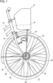
  • 1 eine Teilseitenansicht ist, die ein Fahrrad zeigt, das mit dem Fahrrad-Generator gemäß der ersten Ausführungsform ausgestattet ist;
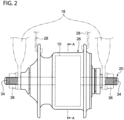
  • 2 eine Vorderansicht ist, die die Ausgestaltung der Fahrradnabe und ihrer Umgebung gemäß der ersten Ausführungsform zeigt;
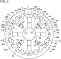
  • 3 eine Querschnittsansicht des Fahrrad-Generators gemäß der ersten Ausführungsform ist;
  • 4 eine Querschnittsansicht ist, die eine Ankerspule des Fahrrad-Generators gemäß der ersten Ausführungsform zeigt;
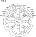
  • 5 eine Ansicht ist, die die Lagebeziehung des Schenkelpolläuferabschnitts und des Schenkelpolständerabschnitts gemäß der ersten Ausführungsform zeigt;
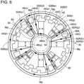
  • 6 eine Ansicht ist, die einen Zustand zeigt, in dem der Phasenwinkel des Generators gemäß der ersten Ausführungsform null ist;
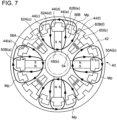
  • 7 eine Ansicht ist, die einen Zustand zeigt, in dem der Phasenwinkel des Generators gemäß der ersten Ausführungsform π/2 ist;
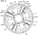
  • 8 eine Ansicht ist, die einen Zustand zeigt, in dem der Phasenwinkel des Generators gemäß der ersten Ausführungsform π ist;
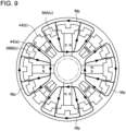
  • 9 eine Ansicht ist, die einen Zustand zeigt, in dem der Phasenwinkel des Generators gemäß der ersten Ausführungsform 3π/2 ist;
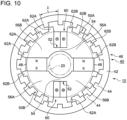
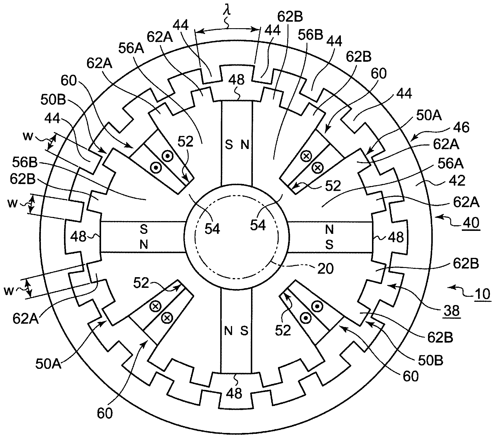
  • 10 eine Querschnittsansicht des Generators gemäß der zweiten Ausführungsform ist;
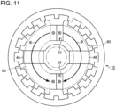
  • 11 eine Querschnittsansicht ist, die eine Ankerspule des Fahrrad-Generators gemäß der zweiten Ausführungsform zeigt;
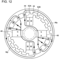
  • 12 eine Ansicht ist, die einen Zustand zeigt, in dem der Phasenwinkel des Generators gemäß der zweiten Ausführungsform null ist;
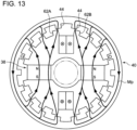
  • 13 eine Ansicht ist, die einen Zustand zeigt, in dem der Phasenwinkel des Generators gemäß der zweiten Ausführungsform π/2 ist;
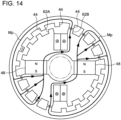
  • 14 eine Ansicht ist, die einen Zustand zeigt, in dem der Phasenwinkel des Generators gemäß der zweiten Ausführungsform π ist; und
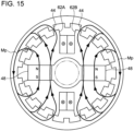
  • 15 eine Ansicht ist, die einen Zustand zeigt, in dem der Phasenwinkel des Generators gemäß der zweiten Ausführungsform 3π/2 ist.
Specific embodiments of the invention will now be described by way of example with reference to the accompanying drawings, in which:
  • 1 is a partial side view showing a bicycle equipped with the bicycle generator according to the first embodiment;
  • 2 is a front view showing the configuration of the bicycle hub and its surroundings according to the first embodiment;
  • 3 is a cross-sectional view of the bicycle generator according to the first embodiment;
  • 4 is a cross-sectional view showing an armature coil of the bicycle generator according to the first embodiment;
  • 5 is a view showing the positional relationship of the salient pole rotor portion and the salient pole stator portion according to the first embodiment;
  • 6 is a view showing a state in which the phase angle of the generator according to the first embodiment is zero;
  • 7 is a view showing a state in which the phase angle of the generator according to the first embodiment is π/2;
  • 8 is a view showing a state in which the phase angle of the generator according to the first embodiment is π;
  • 9 is a view showing a state in which the phase angle of the generator according to the first embodiment is 3π/2;
  • 10 is a cross-sectional view of the generator according to the second embodiment;
  • 11 is a cross-sectional view showing an armature coil of the bicycle generator according to the second embodiment;
  • 12 is a view showing a state in which the phase angle of the generator according to the second embodiment is zero;
  • 13 is a view showing a state in which the phase angle of the generator according to the second embodiment is π/2;
  • 14 is a view showing a state in which the phase angle of the generator according to the second embodiment is π; and
  • 15 is a view showing a state in which the phase angle of the generator according to the second embodiment is 3π/2.

In der Beschreibung jeder der folgenden Ausführungsformen sind denselben Aufbauelementen dieselben Bezugszeichen gegeben worden, und überschneidende Beschreibungen wurden weggelassen. Ferner wurde zur Vereinfachung der Beschreibung, wenn geeignet, in jeder Zeichnung ein Teil der Aufbauelemente weggelassen.In the description of each of the following embodiments, the same constituent elements are given the same reference numerals and overlapping descriptions are omitted. Furthermore, for the convenience of description, a part of the constituent elements is omitted in each drawing where appropriate.

1 ist eine Teilseitenansicht, die ein Fahrrad 12 zeigt, das mit dem Fahrrad-Generator 10 (nachstehend einfach als der Generator 10 bezeichnet) gemäß der ersten Ausführungsform ausgestattet ist. Das Fahrrad 12 weist eine Vorderradgabel 18, die drehbar am Lenkkopf 16 des Hauptrahmens 14 gelagert ist, und eine Nabenwelle 20, die an der Vorderradgabel 18 befestigt ist, auf. Das Vorderrad 22 als ein Rad ist drehbar an der Nabenwelle 20 gelagert. Ein Scheinwerfer 24 ist auf der Seite des Vorderrades 22 montiert, und diesem wird die von dem Generator 10 erhaltene Energie zugeführt. 1 is a partial side view showing a bicycle 12 equipped with the bicycle generator 10 (hereinafter referred to simply as the generator 10) according to the first embodiment. The bicycle 12 has a front fork 18 rotatably supported on the steering head 16 of the main frame 14 and a hub shaft 20 fixed to the front fork 18. The front wheel 22 as a wheel is rotatably supported on the hub shaft 20. A headlight 24 is mounted on the side of the front wheel 22, and the power obtained from the generator 10 is supplied thereto.

Das Vorderrad 22 weist ferner eine röhrenförmige Nabe 26, die über ein Achslager (nicht gezeigt) drehbar an der Nabenwelle 20 gelagert ist, mehrere Speichen 28, die am Außenumfangsteil der Nabe 26 befestigt sind, und eine Felge 30, die am Außenumfangsteil jeder Speiche 28 befestigt ist, auf. Ein Reifen 32 ist an der Felge 30 befestigt.The front wheel 22 further includes a tubular hub 26 rotatably supported on the hub shaft 20 via an axle bearing (not shown), a plurality of spokes 28 secured to the outer peripheral portion of the hub 26, and a rim 30 secured to the outer peripheral portion of each spoke 28. A tire 32 is secured to the rim 30.

2 ist eine Vorderansicht, die die Ausgestaltung der Nabe 26 des Fahrrads 12 und ihre Umgebung zeigt. Andere Ausgestaltungen der Nabe 26 sind durch die Strichzweipunktlinie aufgezeigt. Ein Generator 10, der als ein Nabendynamo agiert, ist in der Nabe 26 untergebracht. Eine Schraube 34 ist an beiden Enden der Nabenwelle 20 in axialer Richtung ausgebildet. Die Nabenwelle 20 wird an der Vorderradgabel 18 zusammen mit der Nabe 26 durch Anziehen einer Mutter 36, die auf die jeweiligen Schrauben 34 geschraubt ist, fixiert. 2 is a front view showing the configuration of the hub 26 of the bicycle 12 and its surroundings. Other configurations of the hub 26 are shown by the two-dot chain line. A generator 10 acting as a hub dynamo is housed in the hub 26. A screw 34 is provided at both ends of the hub shaft 20 in the axial direction. The hub shaft 20 is fixed to the front wheel fork 18 together with the hub 26 by tightening a nut 36 which is screwed onto the respective screws 34.

3 ist eine Querschnittsansicht des Generators 10. Diese Zeichnung ist eine Querschnittsansicht, die senkrecht zur axialen Richtung des Drehzentrums eines nachstehend beschriebenen Läufers 40 und ein Schnitt an der Linie A-A von 2 ist. Die Nabe 26 wurde in der vorliegenden Zeichnung weggelassen. Überdies werden in der folgenden Beschreibung die Ausdrücke „axiale Richtung“, „Umfangsrichtung“ und „radiale Richtung“ zur Beschreibung der Lagebeziehungen der Aufbauelemente des Ständers 38 und des Läufers 40, wie nachstehend beschrieben, verwendet. Von den obigen ist unter „axiale Richtung“ die axiale Richtung des Drehzentrums des Läufers 40 zu verstehen, und unter „Umfangsrichtung“ und „radiale Richtung“ sind die Umfangsrichtung bzw. die radiale Richtung bezogen auf das Drehzentrum des Läufers 40 zu verstehen. 3 is a cross-sectional view of the generator 10. This drawing is a cross-sectional view perpendicular to the axial direction of the rotation center of a rotor 40 described below and a section along the line AA of 2 The hub 26 is omitted from the present drawing. Moreover, in the following description, the terms "axial direction", "circumferential direction" and "radial direction" are used to describe the positional relationships of the constituent elements of the stator 38 and the rotor 40 as described below. Of the above, the "axial direction" means the axial direction of the rotation center of the rotor 40, and the "circumferential direction" and "radial direction" mean the circumferential direction and the radial direction with respect to the rotation center of the rotor 40, respectively.

Der Generator 10 weist einen Ständer 38, der an der Nabenwelle 20 fixiert ist, und einen Läufer 40, der drehbar an der Nabenwelle 20 gelagert ist, auf. Der Generator 10 ist ein Außenläufer-Generator, bei dem der Läufer 40 an der Außenumfangsseite des Ständers 38 angeordnet ist. Ferner ist der Generator 10 ein Synchrongenerator. Der Läufer 40 ist drehbar integral mit der Nabe 26 vorgesehen, die ein Teil des Vorderrades 22 ist. Beim Drehen des Vorderrades 22 dreht sich der Läufer 40 mit.The generator 10 has a stator 38 fixed to the hub shaft 20 and a rotor 40 rotatably mounted on the hub shaft 20. The generator 10 is an external rotor generator in which the rotor 40 is arranged on the outer peripheral side of the stator 38. Furthermore, the generator 10 is a synchronous generator. The rotor 40 is rotatably provided integrally with the hub 26, which is a part of the front wheel 22. When the front wheel 22 rotates, the rotor 40 rotates with it.

Insgesamt ist der Läufer 40 ringförmig ausgebildet. Der Läufer 40 weist ein Läuferblechpaket 46 auf, das einen ringförmigen Grundkörper 42 und mehrere Schenkelpolläuferabschnitte 44 aufweist, die an der Innenumfangsseite des ringförmigen Grundkörpers 42 vorgesehen sind, welche die Seite ist, die dem Ständer 38 des ringförmigen Grundkörpers 42 gegenüber liegt.Overall, the rotor 40 is formed in a ring shape. The rotor 40 has a rotor core 46 which has an annular base body 42 and a plurality of salient pole rotor sections 44 which are provided on the inner peripheral side of the annular base body 42, which is the side opposite the stator 38 of the annular base body 42.

Jeder Schenkelpolläuferabschnitt 44 steht von dem ringförmigen Grundkörper 42 in Richtung der radial inneren Seite, welche die Seite ist, die dem Ständer 38 gegenüber liegt, ab. Jeder Schenkelpolläuferabschnitt 44 ist so ausgebildet, dass er eine der vorgegebenen Breite w entsprechende Breite aufweist. Hier umfasst „entsprechend“ exakt denselben Fall und den im Wesentlichen selben Fall. Die Auslegung von „entsprechend“ wird nachstehend dieselbe sein.Each salient pole rotor portion 44 protrudes from the annular base body 42 toward the radially inner side, which is the side opposite to the stator 38. Each salient pole rotor portion 44 is formed to have a width corresponding to the predetermined width w. Here, "corresponding" includes exactly the same case and substantially the same case. The interpretation of "corresponding" will be the same hereinafter.

Die Schenkelpolläuferabschnitte 44 sind in Abständen an Stellen angeordnet, die jeweils in Umfangsrichtung um einen einem vorgegebenen Winkel λ entsprechenden Winkel (nachstehend auch als die Schenkelpolteilung bezeichnet) verschoben sind. In der vorliegenden Ausführungsform sind insgesamt 20 Schenkelpolläuferabschnitte 44 vorgesehen, wobei die Schenkelpolteilung λ mit 18° (= 360°/20) festgelegt ist. Diese Schenkelpolteilung λ entspricht dem Phasenwinkel 2π des Generators 10; wird der Läufer 40 um die Schenkelpolteilung λ gedreht, wird von der Ankerspule 60 eine Wechselstromleistung erzeugt, die einen Zyklus ausmacht, wie nachstehend beschrieben.The salient pole rotor sections 44 are arranged at intervals at positions each shifted in the circumferential direction by an angle corresponding to a predetermined angle λ (hereinafter also referred to as the salient pole pitch). In the present embodiment, a total of 20 salient pole rotor sections 44 are provided, and the salient pole pitch λ is set to 18° (= 360°/20). This salient pole pitch λ corresponds to the phase angle 2π of the generator 10; when the rotor 40 is rotated by the salient pole pitch λ, an AC power constituting one cycle is generated from the armature coil 60 as described below.

Insgesamt ist der Ständer 38 ringförmig ausgebildet. Der Ständer 38 weist mehrere Magnete 48, die in Abständen in Umfangsrichtung angeordnet sind, und mehrere Ständerblechpakete 50A und 50B, von denen eines für jeden Abstand zwischen den mehreren Magneten 48 angeordnet ist, auf. Die mehreren Magnete 48 und die mehreren Ständerblechpakete 50A und 50B sind abwechselnd in Umfangsrichtung angeordnet und bilden durch Verbinden mittels eines Haftmittels oder dergleichen eine Ringform. In der vorliegenden Ausführungsform sind insgesamt jeweils vier, d. h. eine gerade Zahl, der Magnete 48 und Ständerblechpakete 50A und 50B vorgesehen.As a whole, the stator 38 is formed in a ring shape. The stator 38 has a plurality of magnets 48 arranged at intervals in the circumferential direction and a plurality of stator cores 50A and 50B arranged one for each interval between the plurality of magnets 48. The plurality of magnets 48 and the plurality of stator cores 50A and 50B are alternately arranged in the circumferential direction and form a ring shape by bonding them by means of an adhesive or the like. In the present embodiment, a total of four, i.e., an even number, of the magnets 48 and the stator cores 50A and 50B are provided.

Der Magnet 48 ist ein Dauermagnet. Der Magnet 48 wird im Magnetfeld der nachstehend beschriebenen Ankerspule 60 eingesetzt. Die Umfangsrichtung des Magneten 48 ist die Magnetisierungsrichtung. Die Magnete 48 sind in Abständen an Stellen angeordnet, die in Umfangsrichtung um entsprechende Winkel verschoben sind. Die Magnetpole, die in der Umfangsrichtung der mehreren Magnete 48, die in Umfangsrichtung nebeneinander liegen, entgegengesetzt sind, haben dieselbe Polarität. Die Magnete 48 sind plattenförmig und verlaufen entlang der radialen Richtung, so dass sie in radialer Richtung die Ständerblechpakete 50A und 50B, die in Umfangsrichtung nebeneinander liege, teilen.The magnet 48 is a permanent magnet. The magnet 48 is used in the magnetic field of the armature coil 60 described below. The circumferential direction of the magnet 48 is the magnetization direction. The magnets 48 are arranged at intervals at positions shifted by corresponding angles in the circumferential direction. The magnetic poles opposite in the circumferential direction of the plurality of magnets 48 that are adjacent to each other in the circumferential direction have the same polarity. The magnets 48 are plate-shaped and extend along the radial direction so as to divide in the radial direction the stator cores 50A and 50B that are adjacent to each other in the circumferential direction.

Die Ständerblechpakete 50A und 50B und das oben beschriebene Läuferblechpaket 46 werden durch Schichten mehrerer Metallplatten in der axialen Richtung des Läufers 40 gebildet. Das Material der Metallplatten wird aus einem weichmagnetischen Körper wie einem elektromagnetischen Stahlblech sein.The stator cores 50A and 50B and the rotor core 46 described above are formed by laminating a plurality of metal plates in the axial direction of the rotor 40. The material of the metal plates will be a soft magnetic body such as an electromagnetic steel sheet.

Die Ständerblechpakete 50A und 50B weisen ein erstes Ständerblechpaket 50A, das sich neben einem von den anderen Magneten 48 befindet, die in Umfangsrichtung (in der Zeichnung beispielsweise dem Magneten 48 auf der Oberseite) in einer der Umfangsrichtungen (in der Zeichnung im Uhrzeigersinn) angeordnet sind, und ein zweites Ständerblechpaket 50B, das sich neben dem einen Magneten 48 in der anderen Umfangsrichtung (in der Zeichnung gegen den Uhrzeigersinn) befindet, auf. In der vorliegenden Ausführungsform sind zwei erste Ständerblechpakete 50A und zwei zweite Ständerblechpakete 50B vorgesehen.The stator cores 50A and 50B include a first stator core 50A located adjacent to one of the other magnets 48 arranged in the circumferential direction (for example, the magnet 48 on the top side in the drawing) in one of the circumferential directions (clockwise in the drawing), and a second stator core 50B located adjacent to the one magnet 48 in the other circumferential direction (counterclockwise in the drawing). In the present embodiment, two first stator cores 50A and two second stator cores 50B are provided.

Jedes der Ständerblechpakete 50A und 50B weist die Spulennutabschnitte 52 auf, die an den umfänglich gegenüberliegenden Seiten der anderen Magnete 48 angeordnet sind, die in Umfangsrichtung angeordnet sind. Ein Spulennutabschnitt 52 wird für jeden Abstand zwischen den mehreren Magneten 48 angeordnet sein. Ein Spulennutabschnitt 52 ist für jedes der ersten Ständerblechpakete 50A und jedes der zweiten Ständerblechpakete 50B ausgebildet. Der Spulennutabschnitt 52 ist so ausgebildet, dass er gegenüber der radial äußeren Seite ausgehend von der Seite gegenüber dem Läufer 40 radial nach innen ausgespart ist.Each of the stator cores 50A and 50B has the coil groove portions 52 disposed on the circumferentially opposite sides of the other magnets 48 arranged in the circumferential direction. One coil groove portion 52 will be disposed for each pitch between the plurality of magnets 48. One coil groove portion 52 is formed for each of the first stator cores 50A and each of the second stator cores 50B. The coil groove portion 52 is formed to be recessed radially inward from the side opposite to the rotor 40 from the radially outer side.

Neben dem Spulennutabschnitt 52 weist jedes der Ständerblechpakete 50A und 50B einen bogenförmigen Kraftlinienweg-Verbindungsabschnitt 54, der sich neben dem Spulennutabschnitt 52 auf der Unterseite befindet, und die Kraftlinienwegabschnitte 56A und 56B, die sich neben dem Spulennutabschnitt 52 an den umfänglich gegenüberliegenden Seiten befinden, auf. Der Kraftlinienweg-Verbindungsabschnitt 54 verbindet die Kraftlinienwegabschnitte 56A und 56B in Umfangsrichtung. Die Kraftlinienwegabschnitte 56A und 56B verlaufen zur radial äußeren Seite, welche die Seite ist, die dem Läufer 40 gegenüberliegt. Die Kraftlinienwegabschnitte 56A und 56B weisen einen ersten Kraftlinienwegabschnitt 56A, der sich neben dem Spulennutabschnitt 52 in einer Umfangsrichtung (in der Zeichnung im Uhrzeigersinn) befindet, und einen zweiten Kraftlinienwegabschnitt 56B, der sich neben der anderen Umfangsrichtung (in der Zeichnung gegen den Uhrzeigersinn) befindet, auf.In addition to the coil slot portion 52, each of the stator cores 50A and 50B includes an arcuate flux path connecting portion 54 located adjacent to the coil slot portion 52 on the bottom side, and the flux path portions 56A and 56B located adjacent to the coil slot portion 52 on the circumferentially opposite sides. The flux path connecting portion 54 connects the flux path portions 56A and 56B in the circumferential direction. The flux path portions 56A and 56B extend to the radially outer side, which is the side opposite to the rotor 40. The force line path portions 56A and 56B include a first force line path portion 56A located adjacent to the coil groove portion 52 in one circumferential direction (clockwise in the drawing) and a second force line path portion 56B located adjacent to the other circumferential direction (counterclockwise in the drawing).

4 ist eine Querschnittsansicht, die eine Ankerspule 60 des Generators 10 zeigt. Die Zeichnung zeigt ebenso die Wickelrichtung B der Ankerspule 60 in einer der axialen Richtungen des Läufers 40 (die Nahseite des Blechs). Der Ständer 38 weist ferner die Ankerspulen 60 auf, die zwischen den Spulennutabschnitten 52, die sich neben jedem der Magnete 48 an umfänglich gegenüberliegenden Seiten befinden, gewickelt sind, so dass sie die Magnete 48 in Umfangsrichtung überspreizen. Die Ankerspulen 60 sind entsprechend jedem der mehreren Magnete 48 vorgesehen, und es ist dieselbe Anzahl dieser wie die Anzahl an Magneten 48 vorgesehen. Die Ankerspulen 60 sind so gewickelt, dass sie die entsprechenden Magnete 48 von den umfänglich gegenüberliegenden Seiten und beiden axialen Seiten umgeben. 4 is a cross-sectional view showing an armature coil 60 of the generator 10. The drawing also shows the winding direction B of the armature coil 60 in one of the axial directions of the rotor 40 (the near side of the sheet). The stator 38 further includes the armature coils 60 wound between the coil groove portions 52 located adjacent to each of the magnets 48 on circumferentially opposite sides so as to straddle the magnets 48 in the circumferential direction. The armature coils 60 are provided corresponding to each of the plurality of magnets 48, and the same number of them as the number of magnets 48 is provided. The armature coils 60 are wound so as to surround the corresponding magnets 48 from the circumferentially opposite sides and both axial sides.

Die Ankerspule 60 ist mittels einer konzentrierten Wicklung zwischen den Spulennutabschnitten 52, die in Umfangsrichtung nebeneinander liegen, gewickelt, kann aber auch mittels einer verteilten Wicklung gewickelt sein, so dass sie durch die anderen Spulennutabschnitte 52 hindurchführt. Die Ankerspulen 60, die in Umfangsrichtung nebeneinander liegen, sind in die entgegengesetzte Wickelrichtung B gewickelt, können aber auch in dieselbe Richtung gewickelt sein.The armature coil 60 is wound by means of a concentrated winding between the coil slot portions 52 which are adjacent to each other in the circumferential direction, but may also be wound by means of a distributed winding so as to pass through the other coil slot portions 52. The armature coils 60 which are adjacent to each other in the circumferential direction are wound in the opposite winding direction B, but may also be wound in the same direction.

Wie nachstehend beschrieben, wird, wenn sich der Läufer 40 dreht, die Wechselstromleistung mit derselben Phase in der Ankerspule 60 erzeugt. Die Ankerspulen 60 sind elektrisch parallel geschaltet, und die Ausgangsklemmen sind an eine Gleichrichterschaltung, die nicht gezeigt ist, angeschlossen, und es wird eine Einphasen-Wechselstromleistung an die Gleichrichterschaltung ausgegeben. Die Gleichrichterschaltung wandelt die Wechselstromleistung durch Gleichrichten, Glätten usw. in Gleichstromleistung um und führt die Gleichstromleistung dem Scheinwerfer 24 (bezogen auf 1) als die externe elektrische Vorrichtung zu. Die Ankerspulen 60 können aber auch elektrisch in Reihe geschaltet sein.As described below, when the rotor 40 rotates, the AC power having the same phase is generated in the armature coil 60. The armature coils 60 are electrically connected in parallel, and the output terminals are connected to a rectifier circuit, not shown, and a single-phase AC power is output to the rectifier circuit. The rectifier circuit converts the AC power into DC power by rectifying, smoothing, etc., and supplies the DC power to the headlight 24 (refer to 1 ) as the external electrical device. However, the armature coils 60 can also be electrically connected in series.

Hier, wie in 3 gezeigt, weist der Ständer 38 einen ersten Schenkelpolständerabschnitt 62A, der an jedem von mehreren ersten Kraftlinienwegabschnitten 56A gegenüber dem Läufer 40 vorgesehen ist, und einen zweiten Schenkelpolständerabschnitt 62B, der an jedem der mehreren zweiten Kraftlinienwegabschnitte 56B gegenüber dem Läufer 40 vorgesehen ist, auf. Jeder der Schenkelpolständerabschnitte 62A und 62B steht von jedem der Kraftlinienwegabschnitte 56A und 56B in Richtung der radial äußeren Seite ab, welche die Seite gegenüber dem Läufer 40 ist. Zwei erste Schenkelpolständerabschnitte 62A sind pro einem ersten Kraftlinienwegabschnitt 56A vorgesehen, und zwei zweite Schenkelpolständerabschnitte 62B sind pro einem zweiten Kraftlinienwegabschnitt 56B vorgesehen. In der vorliegenden Ausführungsform sind insgesamt 16 Schenkelpolständerabschnitte 62A und 62B vorgesehen.Here, as in 3 , the stator 38 includes a first salient pole stator portion 62A provided at each of a plurality of first line of force portions 56A opposite to the rotor 40, and a second salient pole stator portion 62B provided at each of a plurality of second line of force portions 56B opposite to the rotor 40. Each of the salient pole stator portions 62A and 62B projects from each of the line of force portions 56A and 56B toward the radially outer side, which is the side opposite to the rotor 40. Two first salient pole stator portions 62A are provided per one first line of force portion 56A, and two second salient pole stator portions 62B are provided per one second line of force portion 56B. In the present embodiment, a total of 16 salient pole stator portions 62A and 62B are provided.

Die Schenkelpolständerabschnitte 62A und 62B sind mit einem vorgegebenen Spalt dazwischen in radialer Richtung bezogen auf den Schenkelpolläuferabschnitt 44 angeordnet. Die Schenkelpolständerabschnitte 62A und 62B sind so ausgebildet, dass sie dieselbe Breite wie die Breite w des Schenkelpolläuferabschnitts 44 aufweisen.The salient pole stator portions 62A and 62B are arranged with a predetermined gap therebetween in the radial direction with respect to the salient pole rotor portion 44. The salient pole stator portions 62A and 62B are formed to have the same width as the width w of the salient pole rotor portion 44.

5 ist eine Ansicht, die die Lagebeziehung des Schenkelpolläuferabschnitts 44 und der Schenkelpolständerabschnitte 62A und 62B zeigt. In der vorliegenden Zeichnung ist zur Unterscheidung eines Teils der mehreren Schenkelpolabschnitte ein Buchstabe aus dem Alphabet, wie (a), am Ende jedes Codes angegeben. Es gibt Fälle, in denen dasselbe in den nachstehenden Zeichnungen gilt. 5 is a view showing the positional relationship of the salient pole rotor portion 44 and the salient pole stator portions 62A and 62B. In the present drawing, in order to distinguish a part of the plurality of salient pole portions, a letter of the alphabet such as (a) is indicated at the end of each code. There are cases where the same applies in the drawings below.

Die mehreren ersten Schenkelpolständerabschnitte 62A, die an einem ersten Kraftlinienwegabschnitt 56A vorgesehen sind, sind an den Stellen angeordnet, die jeweils in Umfangsrichtung um einen Winkel, der der Schenkelpolteilung λ jedes Schenkelpolläuferabschnitts 44 entspricht, verschoben sind. Die mehreren zweiten Schenkelpolständerabschnitte 62B, die an einem zweiten Kraftlinienwegabschnitt 56B vorgesehen sind, sind an den Stellen angeordnet, die jeweils in Umfangsrichtung um einen Winkel, der der Schenkelpolteilung λ entspricht, verschoben sind. Ferner sind die anderen zweiten Schenkelpolständerabschnitte 62B, die in Umfangsrichtung in der Nähe des ersten Schenkelpolständerabschnitts 62A nebeneinander liegen, an den Stellen angeordnet, die jeweils in Umfangsrichtung um einen Winkel, der der Schenkelpolteilung λ × 1,5 entspricht, verschoben sind.The plurality of first salient pole post portions 62A provided on a first force path portion 56A are arranged at the positions each shifted in the circumferential direction by an angle corresponding to the salient pole pitch λ of each salient pole rotor portion 44. The plurality of second salient pole post portions 62B provided on a second force path portion 56B are arranged at the positions each shifted in the circumferential direction by an angle corresponding to the salient pole pitch λ. Further, the other second salient pole post portions 62B adjacent to each other in the circumferential direction near the first salient pole post portion 62A are arranged at the positions each shifted in the circumferential direction by an angle corresponding to the salient pole pitch λ × 1.5.

Wenn daher n eine natürliche Zahl größer als oder gleich 1 ist, sind die ersten Schenkelpolständerabschnitte 62A an Stellen angeordnet, die jeweils in Umfangsrichtung um einen Winkel entsprechend λ × n bezogen auf die anderen ersten Schenkelpolständerabschnitte 62A verschoben sind. Beispielsweise ist der erste Schenkelpolständerabschnitt 62A(d) bezogen auf einen anderen ersten Schenkelpolständerabschnitt 62A(g), der sich im Uhrzeigersinn daneben befindet, um λ × 4 (= λ × 1,5 + λ + λ × 1,5) verschoben, und bezogen auf einen anderen ersten Schenkelpolständerabschnitt 62A(c), der sich gegen den Uhrzeigersinn daneben befindet, um λ × 1,0 verschoben. Dem ähnlich, sind die zweiten Schenkelpolständerabschnitte 62B an den Stellen angeordnet, die jeweils in Umfangsrichtung um einen Winkel entsprechend λ × n bezogen auf die anderen zweiten Schenkelpolständerabschnitte 62B verschoben sind.Therefore, when n is a natural number greater than or equal to 1, the first salient pole post portions 62A are arranged at positions each shifted in the circumferential direction by an angle corresponding to λ × n with respect to the other first salient pole post portions 62A. For example, the first salient pole post portion 62A(d) is shifted by λ × 4 (= λ × 1.5 + λ + λ × 1.5) with respect to another first salient pole post portion 62A(g) located clockwise therebelow, and is shifted by λ × 1.0 with respect to another first salient pole post portion 62A(c) located counterclockwise therebelow. Similarly, the second salient pole post portions 62B are arranged at the positions each shifted in the circumferential direction by an angle corresponding to λ × n with respect to the other second salient pole post portions 62B.

Ferner sind die zweiten Schenkelpolständerabschnitte 62B an Stellen angeordnet, die jeweils in Umfangsrichtung um einen Winkel entsprechend λ × (n + 0,5) bezogen auf die ersten Schenkelpolständerabschnitte 62A verschoben sind. Beispielsweise ist der zweite Schenkelpolständerabschnitt 62B(e) bezogen auf den ersten Schenkelpolständerabschnitt62A(g), der sich im Uhrzeigersinn daneben befindet, um λ × 2,5 (= λ + λ × 1,5) verschoben und bezogen auf den ersten Schenkelpolständerabschnitt 62A(d), der sich gegen den Uhrzeigersinn daneben befindet, um λ × 1,5 verschoben.Further, the second salient pole post portions 62B are arranged at positions each shifted in the circumferential direction by an angle corresponding to λ × (n + 0.5) with respect to the first salient pole post portions 62A. For example, the second salient pole post portion 62B(e) is shifted by λ × 2.5 (= λ + λ × 1.5) with respect to the first salient pole post portion 62A(g) located clockwise therebelow, and is shifted by λ × 1.5 with respect to the first salient pole post portion 62A(d) located counterclockwise therebelow.

Die Betriebsweise des obigen Generators 10 wird unter Verwendung der 6 bis 9 beschrieben. Jede Zeichnung zeigt einen Zustand, in dem der Läufer 40 in Richtung P um einen Phasenwinkel π/2 gedreht wird. Ferner ist in 6 und 8 von dem Magnetfluss, der in dem Läuferblechpaket 46 usw. fließt, hauptsächlich der Fluss des Hauptmagnetflusses gezeigt, und der Fluss des magnetischen Streuflusses wurde weggelassen. Überdies zeigen 7 und 9 den Fluss des magnetischen Streuflusses. Nachstehend ist der Phasenwinkel in der Lagebeziehung von 6 null, und die Phasenwinkel in 7 bis 9 sind π/2, π und 3π/2. Ferner ist zur Vereinfachung eine „O“-Markierung für einen Schenkelpolläuferabschnitt 44(a) angegeben.The operation of the above generator 10 is described using the 6 to 9 Each drawing shows a state in which the rotor 40 is rotated in direction P by a phase angle π/2. Furthermore, 6 and 8 of the magnetic flux flowing in the rotor core 46, etc., mainly the flux of the main magnetic flux is shown, and the flux of the leakage magnetic flux is omitted. Moreover, 7 and 9 the flow of the magnetic leakage flux. Below is the phase angle in the positional relationship of 6 zero, and the phase angles in 7 until 9 are π/2, π and 3π/2. Furthermore, for convenience, an “O” mark is indicated for a salient pole rotor portion 44(a).

Wie in 6 gezeigt, befinden sich, wenn der Phasenwinkel null ist, die ersten Schenkelpolständerabschnitte 62A an Stellen, die die Schenkelpolläuferabschnitte 44 in ihrer Nähe über die gesamte Breite in Umfangsrichtung überlagern, betrachtet aus der radialen Richtung des Läufers 40. Ferner befinden sich die zweiten Schenkelpolständerabschnitte 62B an Stellen, die die Schenkelpolläuferabschnitte 44 in ihrer Nähe über die gesamte Breite in Umfangsrichtung nicht überlagern, das heißt, an Stellen, die in Umfangsrichtung verschoben sind, betrachtet aus der radialen Richtung des Läufers 40. Mit anderen Worten, der Bereich, in dem der erste Schenkelpolständerabschnitt 62A einen Schenkelpolläuferabschnitt 44 in der Nähe in Umfangsrichtung überlagert (nachstehend als der erste Überlagerungsbereich bezeichnet), ist größer als der Bereich, in dem der zweite Schenkelpolständerabschnitt 62B einen anderen Schenkelpolläuferabschnitt 44 in der Nähe in Umfangsrichtung überlagert (nachstehend als der zweite Überlagerungsbereich bezeichnet). Daher wird ein zweiter magnetischer Widerstand R2, welcher der magnetische Widerstand zwischen dem zweiten Schenkelpolständerabschnitt 62B und dem Schenkelpolläuferabschnitt 44 ist, signifikant größer als ein erster magnetischer Widerstand R1, welcher der magnetische Widerstand zwischen dem ersten Schenkelpolständerabschnitt 62A und dem Schenkelpolläuferabschnitt 44 ist.As in 6 , when the phase angle is zero, the first salient pole stator portions 62A are located at positions that overlap the salient pole rotor portions 44 in the vicinity thereof over the entire width in the circumferential direction as viewed from the radial direction of the rotor 40. Further, the second salient pole stator portions 62B are located at positions that do not overlap the salient pole rotor portions 44 in the vicinity thereof over the entire width in the circumferential direction, that is, at positions that are shifted in the circumferential direction as viewed from the radial direction of the rotor 40. In other words, the range in which the first salient pole stator portion 62A overlaps one salient pole rotor portion 44 in the vicinity in the circumferential direction (hereinafter referred to as the first overlap range) is larger than the range in which the second salient pole stator portion 62B overlaps another salient pole rotor portion 44 in the vicinity in the circumferential direction (hereinafter referred to as the second overlap range Therefore, a second magnetic resistance R2, which is the magnetic resistance between the second salient pole stator portion 62B and the salient pole rotor portion 44, becomes significantly larger than a first magnetic resistance R1, which is the magnetic resistance between the first salient pole stator portion 62A and the salient pole rotor portion 44.

Im Ergebnis wird aufgrund des Magnetflusses, der ausgehend von einem Magneten 48 erzeugt wird, ein geschlossener Kraftlinienweg Mp gebildet, der durch den ersten Schenkelpolständerabschnitt 62A des ersten Ständerblechpakets 50A, das sich neben einer Magnetpolfläche des Magneten 48 befindet, und den ersten Schenkelpolständerabschnitt 62A des zweiten Ständerblechpakets 50B, das sich neben der anderen Magnetpolfläche befindet, verläuft. Beispielsweise bildet der Magnet 48(b) im oberen Teil der Zeichnung einen Kraftlinienweg Mp, der den Kraftlinien-Verbindungsabschnitt 54 des ersten Ständerblechpakets 50A(b) → den ersten Kraftlinienwegabschnitt 56A des ersten Ständerblechpakets 50A(b) → den ersten Schenkelpolständerabschnitt 62A(g) → den Schenkelpolläuferabschnitt 44(g) → den ringförmigen Grundkörper 42 → den Läufer 40 → die Schenkelpolläuferabschnitte 44(c) und (d) → die ersten Schenkelpolständerabschnitte 62A(c) und 62A(d) → den ersten Kraftlinienwegabschnitt 56A des zweiten Ständerblechpakets 50B(a) quert und wieder zum ursprünglichen Magneten 48(b) zurückkehrt.As a result, due to the magnetic flux generated from a magnet 48, a closed line of force path Mp is formed which passes through the first salient pole stator portion 62A of the first stator core 50A, which is located adjacent to one magnetic pole surface of the magnet 48, and the first salient pole stator portion 62A of the second stator core 50B, which is located adjacent to the other magnetic pole surface. For example, the magnet 48(b) in the upper part of the drawing forms a force line path Mp which connects the force line connecting portion 54 of the first stator core 50A(b) → the first force line path portion 56A of the first stator core 50A(b) → the first salient pole stator portion 62A(g) → the salient pole rotor portion 44(g) → the annular base body 42 → the rotor 40 → the salient pole rotor portions 44(c) and (d) → the first salient pole stator portions 62A(c) and 62A(d) → the first force line path portion 56A of the second stator core 50B(a) and returns to the original magnet 48(b).

Dieser Kraftlinienweg Mp ist so ausgebildet, dass er sich in jeder der Ankerspulen 60 in radialer Richtung verkettet. Da zu diesem Zeitpunkt die Magnetpole der mehreren Magnete 48, die sich in Umfangsrichtung gegenüberliegen, dieselbe Polarität haben, wird die Drehrichtung des Kraftlinienweges Mp, der von in Umfangsrichtung nebeneinander liegenden Magneten 48 erzeugt wird, entgegengesetzt sein. Beispielsweise wird ein Kraftlinienweg Mp, der von dem Magneten 48(b) im oberen Teil der Zeichnung erzeugt wird, gegen den Uhrzeigersinn verlaufen, und ein Kraftlinienweg Mp, der von dem Magneten 48(b) auf der linken Seite der Zeichnung erzeugt wird, im Uhrzeigersinn verlaufen. Im Ergebnis wird sich der von den separaten Magneten 48 erzeugte Magnetfluss in derselben Ausrichtung in einer Ankerspule 60 verketten. Beispielsweise werden sich der Magnetfluss, der von dem Magneten 48(b) im oberen Teil der Zeichnung erzeugt wird, und der Magnetfluss, der von dem Magneten 48(a) auf der linken Seite der Zeichnung erzeugt wird, in derselben Ausrichtung in der Ankerspule 60(b) im oberen Teil der Zeichnung verketten.This line of force path Mp is formed to interlink in the radial direction in each of the armature coils 60. At this time, since the magnetic poles of the plurality of magnets 48 facing each other in the circumferential direction have the same polarity, the rotation direction of the line of force path Mp generated by magnets 48 adjacent to each other in the circumferential direction will be opposite. For example, a line of force path Mp generated by the magnet 48(b) in the upper part of the drawing will be counterclockwise, and a line of force path Mp generated by the magnet 48(b) on the left side of the drawing will be clockwise. As a result, the magnetic flux generated by the separate magnets 48 will interlink in the same orientation in one armature coil 60. For example, the magnetic flux generated by magnet 48(b) in the upper part of the drawing and the magnetic flux generated by magnet 48(a) on the left side of the drawing will concatenate in the same orientation in armature coil 60(b) in the upper part of the drawing.

Wie in 7 gezeigt, befinden sich bei einem Phasenwinkel π/2 die ersten Schenkelpolständerabschnitte 62A, betrachtet aus der radialen Richtung des Läufers 40, an den Stellen, die die Schenkelpolläuferabschnitte 44 in ihrer Nähe im Wesentlichen über die Hälfte der Breite in Umfangsrichtung überlagern. Gleiches gilt für die zweiten Schenkelpolständerabschnitte 62B. Mit anderen Worten, der erste Überlagerungsbereich des ersten Schenkelpolständerabschnitts 62A bezogen auf den Schenkelpolläuferabschnitt 44 wird dem zweiten Überlagerungsbereich des zweiten Schenkelpolständerabschnitts 62B bezogen auf den Schenkelpolläuferabschnitt 44 entsprechen. Daher werden der erste magnetische Widerstand R1 und der zweite magnetische Widerstand R2 gleich groß werden.As in 7 As shown, at a phase angle π/2, the first salient pole stator portions 62A, viewed from the radial direction of the rotor 40, are located at the locations that overlap the salient pole rotor portions 44 in their vicinity substantially over half the width in the circumferential direction. The same applies to the second salient pole stator portions 62B. In other words, the first overlap area of the first salient pole stator portion 62A with respect to the salient pole rotor portion 44 will correspond to the second overlap area of the second salient pole stator portion 62B with respect to the salient pole rotor portion 44. Therefore, the first magnetic resistance R1 and the second magnetic resistance R2 will become equal.

Im Ergebnis wird aufgrund des Magnetflusses, der von einem Magneten 48 erzeugt wird, ein geschlossener Kraftlinienweg Mp gebildet, der durch den zweiten Schenkelpolständerabschnitt 62B des ersten Ständerblechpakets 50A, das sich neben einer Magnetpolfläche des Magneten 48 befindet, und den ersten Schenkelpolständerabschnitt 62A des zweiten Ständerblechpakets 50B, das sich neben der anderen Magnetpolfläche befindet, verläuft. Beispielsweise bildet der Magnet 48(b) im oberen Teil der Zeichnung einen Kraftlinienweg Mp, der den zweiten Kraftlinienwegabschnitt 56B des ersten Ständerblechpakets 50A(b) → die zweiten Schenkelpolständerabschnitte 62B(e) und (f) → die Schenkelpolläuferabschnitte 44(e) und 44(f) → den ringförmigen Grundkörper 42 → den Läufer 40 → die Schenkelpolläuferabschnitte 44(c) und 44(d) → die ersten Schenkelpolständerabschnitte 62A(c) und (d) → den ersten Kraftlinienwegabschnitt 56A des zweiten Ständerblechpakets 50B(a) quert und wieder zu dem ursprünglichen Magneten 48(b) zurückkehrt. Dieser Kraftlinienweg Mp bewegt sich in jeder Ankerspule 60 in radialer Richtung hin und her und ist so ausgebildet, dass er sich in jeder Ankerspule 60 verkettet. As a result, due to the magnetic flux generated by a magnet 48, a closed line of force path Mp is formed which passes through the second salient pole stator portion 62B of the first stator core 50A located adjacent to one magnetic pole face of the magnet 48 and the first salient pole stator portion 62A of the second stator core 50B located adjacent to the other magnetic pole face. For example, the magnet 48(b) in the upper part of the drawing forms a line of force path Mp that traverses the second line of force path portion 56B of the first stator core 50A(b) → the second salient pole stator portions 62B(e) and (f) → the salient pole rotor portions 44(e) and 44(f) → the annular base 42 → the rotor 40 → the salient pole rotor portions 44(c) and 44(d) → the first salient pole stator portions 62A(c) and (d) → the first line of force path portion 56A of the second stator core 50B(a) and returns to the original magnet 48(b). This line of force path Mp reciprocates in the radial direction in each armature coil 60 and is designed to interlink in each armature coil 60.

Wie in 8 gezeigt, befinden sich bei einem Phasenwinkel π die ersten Schenkelpolständerabschnitte 62A, betrachtet aus der radialen Richtung des Läufers 40, an den Stellen, die die Schenkelpolläuferabschnitte 44 in ihrer Nähe nicht über die gesamte Breite in Umfangsrichtung überlagern, das heißt, den Stellen, die in Umfangsrichtung verschoben sind. Ferner befinden sich die zweiten Schenkelpolständerabschnitte 62B, betrachtet aus der radialen Richtung des Läufers 40, an Stellen, die die Schenkelpolläuferabschnitte 44 in ihrer Nähe über die gesamte Breite in Umfangsrichtung überlagern. Mit anderen Worten, der zweite Überlagerungsbereich des zweiten Schenkelpolständerabschnittes 62B wird bezogen auf den Schenkelpolläuferabschnitt 44 größer sein als der erste Überlagerungsbereich des ersten Schenkelpolständerabschnitts 62A bezogen auf den Schenkelpolläuferabschnitt 44. Daher wird der zweite magnetische Widerstand R2 signifikant größer werden als der erste magnetische Widerstand R1.As in 8 As shown, at a phase angle π, the first salient pole stator portions 62A, as viewed from the radial direction of the rotor 40, are located at the positions that do not overlap the salient pole stator portions 44 in the vicinity thereof over the entire width in the circumferential direction, that is, the positions that are shifted in the circumferential direction. Further, the second salient pole stator portions 62B, as viewed from the radial direction of the rotor 40, are located at positions that overlap the salient pole stator portions 44 in the vicinity thereof over the entire width in the circumferential direction. In other words, the second overlap area of the second salient pole stator portion 62B with respect to the salient pole stator portion 44 will be larger than the first overlap area of the first salient pole stator portion 62A with respect to the salient pole stator portion 44. Therefore, the second magnetic resistance R2 will become significantly larger than the first magnetic resistance R1.

Im Ergebnis wird aufgrund des Magnetflusses, der von einem Magneten 48 erzeugt wird, ein geschlossener Kraftlinienweg Mp gebildet, der durch den zweiten Schenkelpolständerabschnitt 62B des ersten Ständerblechpakets 50A, das sich neben einer Magnetpolfläche des Magneten 48 befindet, und den zweiten Schenkelpolständerabschnitt 62B des zweiten Ständerblechpakets 50B, das sich neben der anderen Magnetpolfläche befindet, verläuft. Beispielsweise bildet der Magnet 48(b) im oberen Teil der Zeichnung einen Kraftlinienweg Mp, der den zweiten Kraftlinienwegabschnitt 56B des ersten Ständerblechpakets 50A(b) → die zweiten Schenkelpolständerabschnitte 62B(e) und (f) → die Schenkelpolläuferabschnitte 44(e) und 44(f) → den ringförmigen Grundkörper 42 → den Läufer 40 → die Schenkelpolläuferabschnitte 44(a) und 44(t) → die zweiten Schenkelpolständerabschnitte 62B(a) und 62B(b) → den Kraftlinienweg-Verbindungsabschnitt 54 des zweiten Ständerblechpakets 50B(a) quert und wieder zu dem ursprünglichen Magneten 48(b) zurückkehrt.As a result, due to the magnetic flux generated by a magnet 48, a closed line of force path Mp is formed which passes through the second salient pole stator portion 62B of the first stator core 50A, which is located adjacent to one magnetic pole face of the magnet 48, and the second salient pole stator portion 62B of the second stator core 50B, which is located adjacent to the other magnetic pole face. For example, the magnet 48(b) in the upper part of the drawing forms a magnetic path Mp that traverses the second magnetic path portion 56B of the first stator core 50A(b) → the second salient pole stator portions 62B(e) and (f) → the salient pole rotor portions 44(e) and 44(f) → the annular base body 42 → the rotor 40 → the salient pole rotor portions 44(a) and 44(t) → the second salient pole stator portions 62B(a) and 62B(b) → the magnetic path connecting portion 54 of the second stator core 50B(a) and returns to the original magnet 48(b).

Dieser Kraftlinienweg Mp ist so ausgebildet, dass er sich in jeder der Ankerspulen 60 in radialer Richtung verkettet. Zu diesem Zeitpunkt ist der Kraftlinienweg Mp so ausgebildet, dass die Verkettungsausrichtung in der Ankerspule 60 im Vergleich zu einem Phasenwinkel null die entgegengesetzte Richtung in der radialen Richtung sein wird (bezogen auf 6).This force line path Mp is designed to interlink in each of the armature coils 60 in the radial direction. At this time, the force line path Mp is designed so that the interlinking orientation in the armature coil 60 is different from a phase angle zero will be the opposite direction in the radial direction (relative to 6 ).

Wie in 9 gezeigt, befinden sich bei einem Phasenwinkel 3π/2 die ersten Schenkelpolständerabschnitte 62A, betrachtet aus der radialen Richtung des Läufers 40, an Stellen, die die Schenkelpolläuferabschnitte 44 in ihrer Nähe im Wesentlichen über die Hälfte der Breite in Umfangsrichtung überlagern. Ferner befinden sich die zweiten Schenkelpolständerabschnitte 62B, betrachtet aus der radialen Richtung des Läufers 40, an den Stellen, die die Schenkelpolläuferabschnitte 44 in ihrer Nähe über die Hälfte der Breite in Umfangsrichtung überlagern. Daher werden der erste magnetische Widerstand R1 und der zweite magnetische Widerstand R2 gleich groß werden. Im Ergebnis wird derselbe Kraftlinienweg Mp wie bei einem Phasenwinkel π/2 gebildet.As in 9 As shown, at a phase angle of 3π/2, the first salient pole stator portions 62A, as viewed from the radial direction of the rotor 40, are located at the positions overlapping the salient pole stator portions 44 in the vicinity thereof for substantially half the width in the circumferential direction. Further, the second salient pole stator portions 62B, as viewed from the radial direction of the rotor 40, are located at the positions overlapping the salient pole stator portions 44 in the vicinity thereof for half the width in the circumferential direction. Therefore, the first magnetic resistance R1 and the second magnetic resistance R2 become equal. As a result, the same line of force path Mp as at a phase angle of π/2 is formed.

Wie oben beschrieben, wird in einem Zustand, in dem der Phasenwinkel null ist, (nachstehend auch als der erste Zustand bezeichnet) der zweite magnetische Widerstand R2 signifikant größer werden als der erste magnetische Widerstand R1, und wird in einem Zustand, in dem der Phasenwinkel 3π/2 ist, (nachstehend als der zweite Zustand bezeichnet) der erste magnetische Widerstand R1 signifikant größer werden als der zweite magnetische Widerstand R2. Dreht sich der Läufer 40, werden der erste Zustand und der zweite Zustand abwechselnd geschaltet.As described above, in a state where the phase angle is zero (hereinafter also referred to as the first state), the second magnetic resistance R2 will become significantly larger than the first magnetic resistance R1, and in a state where the phase angle is 3π/2 (hereinafter referred to as the second state), the first magnetic resistance R1 will become significantly larger than the second magnetic resistance R2. When the rotor 40 rotates, the first state and the second state are alternately switched.

Wie in 6 und 8 gezeigt, wird in einer Ankerspule 60 (zum Beispiel Ankerspule 60(b)) im ersten Zustand ein Kraftlinienweg Mp gebildet, der sich in einer radialen Richtung verkettet, und im zweiten Zustand wird ein Kraftlinienweg Mp gebildet, der sich in der anderen radialen Richtung verkettet. Das heißt, beim Schalten zwischen dem ersten Zustand und dem zweiten Zustand erfolgt das Schalten so, dass die Ausrichtung des Magnetflusses, der sich in der radialen Richtung in jeder Ankerspule 60 verkettet, umgekehrt wird, wodurch eine Wechselstrom-induzierte elektromotorische Kraft in jeder Ankerspule 60 erzeugt wird. Zu diesem Zeitpunkt wird die Wechselstromleistung derselben Phase in jeder Ankerspule 60 erzeugt. Auf diese Weise werden in dem Generator 10 die Stellen der mehreren Schenkelpolläuferabschnitte 44 und der mehreren Schenkelpolständerabschnitte 62A und 62B so bestimmt, dass der erste Zustand und der zweite Zustand abwechselnd geschaltet werden.As in 6 and 8 , in an armature coil 60 (for example, armature coil 60(b)), a line of force path Mp interlinking in one radial direction is formed in the first state, and a line of force path Mp interlinking in the other radial direction is formed in the second state. That is, in switching between the first state and the second state, switching is performed so that the orientation of the magnetic flux interlinking in the radial direction in each armature coil 60 is reversed, thereby generating an AC-induced electromotive force in each armature coil 60. At this time, the AC power of the same phase is generated in each armature coil 60. In this way, in the generator 10, the locations of the plurality of salient pole rotor portions 44 and the plurality of salient pole stator portions 62A and 62B are determined so that the first state and the second state are alternately switched.

Nunmehr werden die Funktionsweise und Wirkungen des Generators 10 beschrieben.The operation and effects of the generator 10 will now be described.

Im Allgemeinen erfüllt die Frequenz f (Hz) eines Generators die Beziehung der folgenden Formel (1) zwischen der Drehzahl N (U/min) des Läufers und der Anzahl von Polen P des Generators. N = 120 × f / P

Figure DE102016201848B4_0001
In general, the frequency f (Hz) of a generator satisfies the relationship of the following formula (1) between the rotational speed N (rpm) of the rotor and the number of poles P of the generator. N = 120 × f / P
Figure DE102016201848B4_0001

Die betreffenden Erfinder haben die Erkenntnis gewonnen, dass bei dem Generator 10 gemäß der vorliegenden Ausführungsform die Anzahl, erhalten durch Multiplizieren der Anzahl an Schenkelpolläuferabschnitten 44 mit zwei, die Anzahl der Pole P des Generators ergibt. Diese Erkenntnis wurde durch die Analyse unter Anwendung des in 3 gezeigten Aufbaus gewonnen. Bei dieser Analyse wurde die Drehzahl N des Läufers 40 auf 120 (U/min) eingestellt, wodurch die Frequenz f (Hz) der Leistung, die von der Ankerspule 60 erzeugt wird, erhalten wurde. Im Ergebnis wurde eine Frequenz f von 40 (Hz) erhalten, und durch die Formel (1) wurde die Anzahl, erhalten durch Multiplizieren der Anzahl an Schenkelpolläuferabschnitten 44 (20) mit zwei, als die Anzahl der Pole P des Generators bestätigt.The present inventors have found that in the generator 10 according to the present embodiment, the number obtained by multiplying the number of salient pole rotor sections 44 by two gives the number of poles P of the generator. This finding was confirmed by the analysis using the formula given in 3 was obtained. In this analysis, the rotational speed N of the rotor 40 was set to 120 (rpm), thereby obtaining the frequency f (Hz) of the power generated by the armature coil 60. As a result, a frequency f of 40 (Hz) was obtained, and by the formula (1), the number obtained by multiplying the number of salient pole rotor sections 44 (20) by two was confirmed as the number of poles P of the generator.

So wird sich bei dem Generator 10 gemäß der vorliegenden Ausführungsform, solange sich die Schenkelpolläuferabschnitte 44 und die Schenkelpolständerabschnitte 62A und 62B an den vorgegebenen Stellen befinden, die Frequenz der induzierten elektromotorischen Kraft erhöhen, wenn sich die Anzahl an Schenkelpolläuferabschnitten 44 erhöht, und es wird leicht eine Hochfrequenz-Wechselstromleistung erhalten, selbst wenn die Drehzahl des Läufers 40 niedrig ist. Da jedoch die Spannung der induzierten elektromotorischen Kraft proportional zu dem Produkt der Frequenz und des Magnetflusses, der sich in der Ankerspule 60 verkettet, ist, bedeutet die Fähigkeit zum Erhalt der Hochfrequenz-Wechselstromleistung, dass eine entsprechende Hochspannungs-Wechselstromleistung erhalten werden kann.Thus, in the generator 10 according to the present embodiment, as long as the salient pole rotor portions 44 and the salient pole stator portions 62A and 62B are located at the predetermined positions, the frequency of the induced electromotive force will increase as the number of the salient pole rotor portions 44 increases, and high frequency AC power is easily obtained even when the rotational speed of the rotor 40 is low. However, since the voltage of the induced electromotive force is proportional to the product of the frequency and the magnetic flux concatenated in the armature coil 60, the ability to obtain the high frequency AC power means that a corresponding high voltage AC power can be obtained.

Ferner sind der erste Schenkelpolständerabschnitt 62A und der zweite Schenkelpolständerabschnitt 62B an Stellen zwischen dem Magneten 48 und dem Spulennutabschnitt 52 vorgesehen, so können die Abstände dazwischen noch leichter getrennten werden. Daher kann, selbst wenn diese zu unterschiedlichen Polaritäten von dem Magneten 48 angeregt werden, die Erzeugung des magnetischen Streuflusses zwischen dem ersten Schenkelpolständerabschnitt 62A und dem zweiten Schenkelpolständerabschnitt 62B leichter unterdrückt werden. Aus diesem Grund wird die Unterdrückung des magnetischen Streuflusses dazwischen bei gleichzeitiger Verringerung des Außendurchmessers des Läufers 40 und des Ständers 38 des Generators 10 leicht. Die Fähigkeit zur Unterdrückung der Erzeugung eines magnetischen Streuflusses zwischen dem ersten Schenkelpolständerabschnitt 62A und dem zweiten Schenkelpolständerabschnitt 62B bedeutet jedoch, dass eine Verringerung des Magnetflusses, der sich in der Ankerspule 60 verkettet, unterdrückt werden kann und der Erhalt einer ausreichenden Spannungsausgabe aus dem Generator 10 leichter wird.Further, the first salient pole stator portion 62A and the second salient pole stator portion 62B are provided at locations between the magnet 48 and the coil groove portion 52, so the spaces therebetween can be separated more easily. Therefore, even if they are excited to different polarities by the magnet 48, the generation of the leakage magnetic flux between the first salient pole stator portion 62A and the second salient pole stator portion 62B can be suppressed more easily. For this reason, suppression of the leakage magnetic flux therebetween becomes easy while reducing the outer diameter of the rotor 40 and the stator 38 of the generator 10. However, the ability to suppress the generation of leakage magnetic flux between the first salient pole stator portion 62A and the second salient pole stator portion 62B means that a reduction in the magnetic flux interlinked in the armature coil 60 can be suppressed. and obtaining sufficient voltage output from the generator 10 becomes easier.

Überdies erhöht sich beispielsweise bei einem Dreiphasenwechselstrom-Generator, bei dem eine Ankerspule um jeden von mehreren Schenkelpolabschnitten eines Ständers gewickelt ist, wie dem in der japanischen Offenlegungsschrift 2012-182961 offenbarten, die Anzahl der Ankerspulen zusammen mit einer Erhöhung der Anzahl der Magnetpole des Läufers, was zu entsprechend hohen Kosten und einer Herabsetzung der Montageeigenschaften führt. Diesbezüglich muss in der vorliegenden Ausführungsform zum Erhalt der Hochfrequenz-Wechselstromleistung nur die Anzahl der Schenkelpolläuferabschnitte 44 erhöht werden, und die Anzahl der Magnete 48 oder der Ankerspulen 60 muss nicht erhöht werden; daher kann die Teilezahl verringert werden, was wiederum die Kosten reduziert, und es können gute Montageeigenschaften erhalten werden.Moreover, for example, in a three-phase AC generator in which an armature coil is wound around each of several salient pole sections of a stator, such as that shown in Japanese Laid-Open Application 2012-182961 disclosed, the number of armature coils increases along with an increase in the number of magnetic poles of the rotor, resulting in a correspondingly high cost and a reduction in assembly properties. In this regard, in the present embodiment, in order to obtain the high frequency AC power, only the number of the salient pole rotor sections 44 needs to be increased, and the number of the magnets 48 or the armature coils 60 does not need to be increased; therefore, the number of parts can be reduced, which in turn reduces the cost, and good assembly properties can be obtained.

Überdies ändert bei einem herkömmlichen Klauenpolgenerator der Magnetfluss, der vom Magneten des Läufers in die Klauenabschnitte jedes Ständerblechpakets fließt, in dem Klauenabschnitt die Richtung in die axiale Richtung und fließt in Richtung des Grundkörpers des Klauenabschnitts. Die Querschnittsfläche des Kraftlinienweges, der senkrecht zur Kraftlinienwegrichtung dieses Klauenabschnitts ist (axiale Richtung), wird gemäß der Dicke und dem Umfang des Klauenabschnitts in radialer Richtung bestimmt. Hier wird, wenn der Außendurchmesser verringert wird, ohne die axiale Länge des Generators zu verändern, der Klauenabschnitt des Ständerblechpakets in Umfangsrichtung dünner, ohne dass die axiale Länge verändert wird, so dass die Spaltfläche, die dem Magneten gegenüber liegt, dünn und die Dicke in radialer Richtung verringert wird; im Ergebnis wird die Querschnittsfläche des Kraftlinienweges am Grundabschnitt des Klauenabschnitts klein. Daher wird tendenziell der Magnetfluss, den der Klauenabschnitt des Ständerblechpakets an der Spaltfläche aufnimmt, am Grundabschnitt des Klauenabschnitts mit einer kleinen Querschnittsfläche des Kraftlinienweges konzentriert, und es wird am Grundabschnitt wahrscheinlich zu einer magnetischen Sättigung kommen. Im Ergebnis kann der Magnetfluss, der sich in der Ankerspule verkettet, nur schwer fließen, und auch der Erhalt einer ausreichenden Spannungsausgabe aus dem Generator wird schwierig.Moreover, in a conventional claw pole generator, the magnetic flux flowing from the magnet of the rotor into the claw portions of each stator core changes direction to the axial direction in the claw portion and flows toward the base body of the claw portion. The cross-sectional area of the line of force path perpendicular to the line of force path direction of this claw portion (axial direction) is determined according to the thickness and circumference of the claw portion in the radial direction. Here, when the outer diameter is reduced without changing the axial length of the generator, the claw portion of the stator core becomes thinner in the circumferential direction without changing the axial length, so that the gap area facing the magnet is thin and the thickness in the radial direction is reduced; as a result, the cross-sectional area of the line of force path at the base body of the claw portion becomes small. Therefore, the magnetic flux received by the claw portion of the stator core at the gap surface tends to be concentrated at the base portion of the claw portion with a small cross-sectional area of the line of force path, and magnetic saturation is likely to occur at the base portion. As a result, the magnetic flux interlinked in the armature coil becomes difficult to flow, and obtaining sufficient voltage output from the generator also becomes difficult.

Diesbezüglich fließt bei dem Generator 10 gemäß der vorliegenden Ausführungsform der Magnetfluss in den Schenkelpolständerabschnitten 62A und 62B des Ständerblechpakets 50 nicht in axialer Richtung sondern in radialer Richtung. Die Querschnittsfläche des Kraftlinienweges, der senkrecht zur Kraftlinienwegrichtung dieser Schenkelpolständerabschnitte 62A und 62B (radiale Richtung) ist, wird gemäß der axialen Länge und dem Umfang der Schenkelpolständerabschnitte 62A und 62B bestimmt, die nicht so leicht verändert werden, selbst wenn der Außendurchmesser des Generators 10 verringert wird. Aus diesem Grund können, selbst wenn der Außendurchmesser des Generators 10 verringert wird, die Querschnittsfläche des Kraftlinienweges der Schenkelpolständerabschnitte 62A und 62B sichergestellt werden, indem die axiale Länge des Ständerblechpakets 50 erhöht wird. Daher kann, selbst wenn der Außendurchmesser des Generators 10 verringert wird, das Auftreten einer magnetischen Sättigung der Schenkelpolständerabschnitte 62A und 62B unterdrückt werden, eine Reduktion des Magnetflusses, der sich in der Ankerspule 60 verkettet, unterdrückt werden, und der Erhalt einer ausreichenden Spannungsausgabe aus dem Generator 10 wird leichter.In this regard, in the generator 10 according to the present embodiment, the magnetic flux in the salient pole stator portions 62A and 62B of the stator core 50 does not flow in the axial direction but in the radial direction. The cross-sectional area of the line of force path that is perpendicular to the line of force path direction of these salient pole stator portions 62A and 62B (radial direction) is determined according to the axial length and circumference of the salient pole stator portions 62A and 62B, which are not easily changed even if the outer diameter of the generator 10 is reduced. For this reason, even if the outer diameter of the generator 10 is reduced, the cross-sectional area of the line of force path of the salient pole stator portions 62A and 62B can be ensured by increasing the axial length of the stator core 50. Therefore, even if the outer diameter of the generator 10 is reduced, the occurrence of magnetic saturation of the salient pole stator portions 62A and 62B can be suppressed, a reduction in the magnetic flux interlinking in the armature coil 60 can be suppressed, and obtaining a sufficient voltage output from the generator 10 becomes easier.

Überdies kann bei jedem Schalten des ersten Zustands und des zweiten Zustands die Ausrichtung des Kraftlinienweges Mp, der durch den einen Magneten 48 in der Ankerspule 60 erzeugt wird, umgekehrt werden, was im Vergleich zu einer nicht umgekehrten Ausrichtung eine größere Veränderungsmenge des Magnetflusses, der sich in der Ankerspule 60 verkettet, erlaubt; daher kann noch einfacher eine Hochspannungs-Wechselstromleistung erhalten werden. Überdies kann bei jedem Schalten des ersten Zustands und des zweiten Zustands die Ausrichtung des Kraftlinienwegs Mp, der in der einen Ankerspule 60, die einen Magneten 48 nutzt, erzeugt wird, umgekehrt werden; daher kann einfacher eine Hochspannungs-Wechselstromleistung erhalten werden, während gleichzeitig die Anzahl von Magneten 48 verringert wird.Moreover, at each switching of the first state and the second state, the orientation of the line of force path Mp generated by the one magnet 48 in the armature coil 60 can be reversed, allowing a larger amount of change in the magnetic flux interlinked in the armature coil 60 compared with a non-reversed orientation; therefore, high-voltage AC power can be obtained more easily. Moreover, at each switching of the first state and the second state, the orientation of the line of force path Mp generated in the one armature coil 60 using one magnet 48 can be reversed; therefore, high-voltage AC power can be obtained more easily while reducing the number of magnets 48.

Ferner ist jeder der ersten Schenkelpolständerabschnitte 62A bezogen auf einen anderen der ersten Schenkelpolständerabschnitte 62A um einen Winkel entsprechend λ × n verschoben, und jeder der zweiten Schenkelpolständerabschnitte 62B ist bezogen auf den ersten Schenkelpolständerabschnitt 62A um einen Winkel entsprechend λ × (n + 0,5) verschoben. Daher können die Relativlagen der Schenkelpolständerabschnitte 62A und 62B bezogen auf den Schenkelpolläuferabschnitt 44 ausgerichtet werden, die Art und Weise der Änderung des Kraftlinienwegs Mp, der von dem aus den Magneten 48 erzeugten Magnetfluss gebildet wird, kann angepasst werden und mit der Ankerspule 60 leichter eine Wechselstromleistung mit derselben Phase erhalten werden.Further, each of the first salient pole stator portions 62A is shifted relative to another of the first salient pole stator portions 62A by an angle corresponding to λ × n, and each of the second salient pole stator portions 62B is shifted relative to the first salient pole stator portion 62A by an angle corresponding to λ × (n + 0.5). Therefore, the relative positions of the salient pole stator portions 62A and 62B with respect to the salient pole rotor portion 44 can be aligned, the manner of changing the line of force path Mp formed by the magnetic flux generated from the magnets 48 can be adjusted, and an AC power having the same phase can be obtained more easily with the armature coil 60.

Ferner kann, da jedes der Ständerblechpakete 50A und 50B und das Läuferblechpaket 46 durch Schichten mehrerer Metallplatten gebildet werden können, der Erregungsverlust aufgrund eines Wirbelstroms in dem Abschnitt, durch den der Hauptmagnetfluss verläuft, signifikant unterdrückt werden.Furthermore, since each of the stator cores 50A and 50B and the rotor core 46 can be formed by laminating a plurality of metal plates, the excitation loss due to a eddy current in the section through which the main magnetic flux passes can be significantly suppressed.

10 ist eine Querschnittsansicht, die den Generator 10 gemäß der zweiten Ausführungsform zeigt, und 11 ist eine Querschnittsansicht, die eine Ankerspule 60 des Generators 10 zeigt. In dem Beispiel von 3 sind insgesamt 20 Schenkelpolläuferabschnitte 44 des Läufers 40 vorgesehen, in der vorliegenden Ausführungsform sind jedoch insgesamt 18 vorgesehen. Die Schenkelpolteilung λ wird 20° (= 360° / 18) betragen. 10 is a cross-sectional view showing the generator 10 according to the second embodiment, and 11 is a cross-sectional view showing an armature coil 60 of the generator 10. In the example of 3 A total of 20 salient pole rotor sections 44 of the rotor 40 are provided, but in the present embodiment a total of 18 are provided. The salient pole pitch λ will be 20° (= 360° / 18).

Im Beispiel von 3 sind insgesamt vier Magnete 48 und Ständerblechpakete 50A und 50B des Ständers 38 vorgesehen, in der vorliegenden Ausführungsform sind jedoch insgesamt jeweils zwei vorgesehen. Ferner sind im Beispiel von 3 jeweils zwei erste Ständerblechpakete 50A und zweite Ständerblechpakete 50B vorgesehen, in der vorliegenden Ausführungsform ist jedoch jeweils nur einer vorgesehen. Ferner sind in dem Beispiel von 3 jeweils zwei erste Schenkelpolständerabschnitte 62A und zweite Schenkelpolständerabschnitte 62B am ersten Kraftlinienwegabschnitt 56A und zweiten Kraftlinienwegabschnitt 56B vorgesehen, in der vorliegenden Ausführungsform sind jedoch jeweils vier vorgesehen. So ist die Anzahl der Schenkelpolläuferabschnitte 44 und der Schenkelpolständerabschnitte 62A und 62B nicht besonders eingeschränkt.In the example of 3 A total of four magnets 48 and stator cores 50A and 50B of the stator 38 are provided, but in the present embodiment a total of two are provided. Furthermore, in the example of 3 Two first stator cores 50A and two second stator cores 50B are provided, but in the present embodiment only one is provided. Furthermore, in the example of 3 Two first salient pole stator portions 62A and second salient pole stator portions 62B are provided at the first line of force path portion 56A and the second line of force path portion 56B, respectively, but four are provided at each of the present embodiment. Thus, the number of the salient pole rotor portions 44 and the salient pole stator portions 62A and 62B is not particularly limited.

Die Betriebsweise des obigen Generators 10 wird unter Verwendung der 12 bis 15 beschrieben. Jede Zeichnung zeigt einen Zustand, in dem der Läufer 40 in der Richtung P um einen Phasenwinkel π/2 gedreht ist. Ferner ist in 12 und 14 von dem Magnetfluss, der im Läuferblechpaket 46 usw. fließt, hauptsächlich der Fluss des Hauptmagnetflusses gezeigt, und der Fluss des magnetischen Streuflusses wurde weggelassen. Überdies zeigen 13 und 15 den Fluss des magnetischen Streuflusses. Nachstehend ist der Phasenwinkel in der Lagebeziehung von 12 null, und die Phasenwinkel in 13 bis 15 betragen π/2, π und 3π/2.The operation of the above generator 10 is described using the 12 until 15 Each drawing shows a state in which the rotor 40 is rotated in the direction P by a phase angle π/2. Furthermore, in 12 and 14 of the magnetic flux flowing in the rotor core 46, etc., mainly the flux of the main magnetic flux is shown, and the flux of the leakage magnetic flux is omitted. Moreover, 13 and 15 the flow of the magnetic leakage flux. Below is the phase angle in the positional relationship of 12 zero, and the phase angles in 13 until 15 are π/2, π and 3π/2.

Wie in 12 gezeigt, befinden sich, wenn der Phasenwinkel null ist, die ersten Schenkelpolständerabschnitte 62A, betrachtet aus der radialen Richtung des Läufers 40, an Stellen, die die Schenkelpolläuferabschnitte 44 in ihrer Nähe über die gesamte Breite in Umfangsrichtung überlagern. Die zweiten Schenkelpolständerabschnitte 62B befinden sich an Stellen, die die Schenkelpolläuferabschnitte 44 in ihrer Nähe nicht über die gesamte Breite in Umfangsrichtung überlagern, das heißt, an Stellen, die, betrachtet aus der radialen Richtung des Läufers 40, in Umfangsrichtung verschoben sind. Mit anderen Worten, der erste Überlagerungsbereich des ersten Schenkelpolständerabschnitts 62A bezogen auf den Schenkelpolläuferabschnitt 44 wird größer sein als der zweite Überlagerungsbereich des zweiten Schenkelpolständerabschnitts 62B bezogen auf den Schenkelpolläuferabschnitt 44. So wird ein geschlossener Kraftlinienweg Mp derart gebildet, dass er sich in der radialen Richtung in jeder Ankerspule 60 verkettet, genau wie in der ersten Ausführungsform.As in 12 As shown, when the phase angle is zero, the first salient pole stator portions 62A are located at positions overlapping the salient pole stator portions 44 in the vicinity thereof over the entire width in the circumferential direction as viewed from the radial direction of the rotor 40. The second salient pole stator portions 62B are located at positions not overlapping the salient pole stator portions 44 in the vicinity thereof over the entire width in the circumferential direction, that is, at positions shifted in the circumferential direction as viewed from the radial direction of the rotor 40. In other words, the first overlapping area of the first salient pole stator portion 62A with respect to the salient pole rotor portion 44 will be larger than the second overlapping area of the second salient pole stator portion 62B with respect to the salient pole rotor portion 44. Thus, a closed line of force path Mp is formed so as to interlink in the radial direction in each armature coil 60, just as in the first embodiment.

Wie in 13 gezeigt, befinden sich, wenn der Phasenwinkel π/2 ist, die ersten Schenkelpolständerabschnitte 62A, betrachtet aus der radialen Richtung des Läufers 40, an Stellen, die die Schenkelpolläuferabschnitte 44 in ihrer Nähe über die Hälfte der Breite in Umfangsrichtung überlagern. Ferner befinden sich die zweiten Schenkelpolständerabschnitte 62B, betrachtet aus der radialen Richtung des Läufers 40, an Stellen, die die Schenkelpolläuferabschnitte 44 in ihrer Nähe nicht über die Hälfte der Breite in Umfangsrichtung überlagern. Mit anderen Worten, der erste Überlagerungsbereich des ersten Schenkelpolständerabschnitts 62A bezogen auf den Schenkelpolläuferabschnitt 44 wird dem zweiten Überlagerungsbereich des zweiten Schenkelpolständerabschnitts 62B bezogen auf den Schenkelpolläuferabschnitt 44 entsprechen. So wird ein geschlossener Kraftlinienweg Mp derart gebildet, dass er sich in jeder der Ankerspulen 60 in der radialen Richtung hin und her bewegt, genau wie in der ersten Ausführungsform.As in 13 As shown, when the phase angle is π/2, the first salient pole stator portions 62A, as viewed from the radial direction of the rotor 40, are located at positions overlapping the salient pole stator portions 44 in their vicinity over half the width in the circumferential direction. Further, the second salient pole stator portions 62B, as viewed from the radial direction of the rotor 40, are located at positions not overlapping the salient pole stator portions 44 in their vicinity over half the width in the circumferential direction. In other words, the first overlapping area of the first salient pole stator portion 62A with respect to the salient pole stator portion 44 will correspond to the second overlapping area of the second salient pole stator portion 62B with respect to the salient pole stator portion 44. Thus, a closed line of force path Mp is formed so as to reciprocate in the radial direction in each of the armature coils 60, just as in the first embodiment.

Wie in 14 gezeigt, befinden sich, wenn der Phasenwinkel π ist, die ersten Schenkelpolständerabschnitte 62A, betrachtet aus der radialen Richtung des Läufers 40, an Stellen, die die Schenkelpolläuferabschnitte 44 in ihrer Nähe nicht über die gesamte Breite in Umfangsrichtung überlagern, das heißt, an Stellen, die in Umfangsrichtung verschoben sind. Die zweiten Schenkelpolständerabschnitte 62B befinden sich, betrachtet aus der radialen Richtung des Läufers 40, an Stellen, die die Schenkelpolläuferabschnitte 44 in ihrer Nähe über die gesamte Breite in Umfangsrichtung überlagern. Mit anderen Worten, der zweite Überlagerungsbereich des zweiten Schenkelpolständerabschnitts 62B bezogen auf den Schenkelpolläuferabschnitt 44 wird größer sein als der erste Überlagerungsbereich des ersten Schenkelpolständerabschnitts 62A bezogen auf den Schenkelpolläuferabschnitt 44. So wird ein geschlossener Kraftlinienweg Mp derart gebildet, dass er sich in der radialen Richtung in jeder Ankerspule 60 verkettet, genau wie in der ersten Ausführungsform.As in 14 As shown, when the phase angle is π, the first salient pole stator portions 62A, as viewed from the radial direction of the rotor 40, are located at positions not overlapping the salient pole rotor portions 44 in the vicinity thereof over the entire width in the circumferential direction, that is, at positions shifted in the circumferential direction. The second salient pole stator portions 62B are located at positions overlapping the salient pole rotor portions 44 in the vicinity thereof over the entire width in the circumferential direction, as viewed from the radial direction of the rotor 40. In other words, the second overlapping area of the second salient pole stator portion 62B with respect to the salient pole rotor portion 44 will be larger than the first overlapping area of the first salient pole stator portion 62A with respect to the salient pole rotor portion 44. Thus, a closed line of force path Mp is formed so as to interlink in the radial direction in each armature coil 60, just as in the first embodiment.

Wie in 15 gezeigt, befinden sich, wenn der Phasenwinkel 3π/2 ist, die ersten Schenkelpolständerabschnitte 62A, betrachtet aus der radialen Richtung des Läufers 40, an Stellen, die die Schenkelpolläuferabschnitte 44 in ihrer Nähe über die Hälfte der Breite in Umfangsrichtung überlagern. Ferner befinden sich die zweiten Schenkelpolständerabschnitte 62B, betrachtet aus der radialen Richtung des Läufers 40, an Stellen, die die Schenkelpolläuferabschnitte 44 in ihrer Nähe über die Hälfte der Breite in Umfangsrichtung überlagern. Im Ergebnis wird derselbe Kraftlinienweg Mp wie beim Phasenwinkel π/2 gebildet.As in 15 As shown, when the phase angle is 3π/2, the first salient pole stator portions 62A, viewed from the radial direction of the rotor 40, are located at positions overlapping the salient pole stator portions 44 in their vicinity over half the width in the circumferential direction. Further, the second salient pole stators r sections 62B, viewed from the radial direction of the rotor 40, at locations which overlap the salient pole rotor sections 44 in their vicinity over half the width in the circumferential direction. As a result, the same line of force path Mp as at the phase angle π/2 is formed.

Die betreffenden Erfinder haben die Erkenntnis gewonnen, dass auch bei dem obigen Generator 10 die Anzahl, erhalten durch Multiplizieren der Anzahl an Schenkelpolläuferabschnitten 44 mit zwei, die Anzahl der Pole P des Generators ergibt. Diese Erkenntnis wurde durch die Analyse unter Anwendung des in 10 gezeigten Aufbaus gewonnen. Bei dieser Analyse wurde die Drehzahl N des Läufers 40 auf 120 (U/min) eingestellt, wodurch die Frequenz f (Hz) der Leistung, die von der Ankerspule 60 erzeugt wird, erhalten wurde. Im Ergebnis wurde eine Frequenz f von 36 (Hz) erhalten, und durch die Formel (1) wurde die Anzahl, erhalten durch Multiplizieren der Anzahl an Schenkelpolläuferabschnitten 44 (18) mit zwei, als die Anzahl der Pole P des Generators bestätigt.The inventors concerned have found that also in the above generator 10, the number obtained by multiplying the number of salient pole rotor sections 44 by two gives the number of poles P of the generator. This finding was confirmed by the analysis using the method described in 10 In this analysis, the rotational speed N of the rotor 40 was set to 120 (rpm), thereby obtaining the frequency f (Hz) of the power generated by the armature coil 60. As a result, a frequency f of 36 (Hz) was obtained, and by the formula (1), the number obtained by multiplying the number of salient pole rotor sections 44 (18) by two was confirmed as the number of poles P of the generator.

Daher wird auch bei dem Generator 10 gemäß der vorliegenden Ausführungsform die Frequenz der induzierten elektromotorischen Kraft bei einer Erhöhung der Anzahl an Schenkelpolläuferabschnitten 44 steigen, und es kann einfacher eine Hochfrequenz-Wechselstromleistung erhalten werden, selbst wenn die Drehzahl des Läufers 40 niedrig ist, genau wie in der ersten Ausführungsform. Auch in anderer Hinsicht können dieselbe Funktionsweise und Wirkungen wie in der ersten Ausführungsform erhalten werden.Therefore, in the generator 10 according to the present embodiment, the frequency of the induced electromotive force increases as the number of salient pole rotor sections 44 increases, and high frequency AC power can be obtained more easily even when the rotation speed of the rotor 40 is low, just like in the first embodiment. In other respects, the same operation and effects as in the first embodiment can be obtained.

Die vorliegende Erfindung wurde oben basierend auf den Ausführungsformen beschrieben, die Ausführungsformen veranschaulichen aber lediglich die Prinzipien und Anwendungen der vorliegenden Erfindung. Ferner können zahlreiche Modifikationen und Veränderungen der Anordnung an der Ausführungsform vorgenommen werden, ohne vom Sinn der vorliegenden Erfindung, wie sie in den Ansprüchen festgelegt ist, abzuweichen.The present invention has been described above based on the embodiments, but the embodiments merely illustrate the principles and applications of the present invention. Furthermore, various modifications and changes of arrangement can be made to the embodiment without departing from the spirit of the present invention as defined in the claims.

Der Generator 10 wurde am Beispiel eines Fahrrad-Generators beschrieben, dessen Verwendung ist aber nicht darauf beschränkt. Soll ferner der Generator 10 ein Fahrrad-Generator sein, muss sich der Läufer 40 lediglich in Verbindung mit der Drehung eines rotierenden Teils des Fahrrads 12 drehen. Das rotierende Teil wurde hier am Beispiel des Vorderrades 22 beschrieben, neben einer Nabenwelle und einer Kurbel kann das Teil aber auch eine Rolle oder dergleichen eines hinteren Umwerfers (Kettenspanners) sein. Ferner kann der Generator 10 nicht nur als ein Nabendynamo, sondern auch als ein Rollendynamo oder dergleichen ausgebildet sein. Als ein Beispiel für den Generator 10 wurde ein Außenläufer-Generator gezeigt, der Generator kann aber auch ein Innenläufer-Generator sein, bei dem der Läufer 40 an der Innenumfangsseite des Ständers 38 angeordnet ist.The generator 10 was described using the example of a bicycle generator, but its use is not limited to this. Furthermore, if the generator 10 is to be a bicycle generator, the rotor 40 only has to rotate in conjunction with the rotation of a rotating part of the bicycle 12. The rotating part was described here using the example of the front wheel 22, but in addition to a hub shaft and a crank, the part can also be a roller or the like of a rear derailleur (chain tensioner). Furthermore, the generator 10 can be designed not only as a hub dynamo, but also as a roller dynamo or the like. An external rotor generator was shown as an example of the generator 10, but the generator can also be an internal rotor generator in which the rotor 40 is arranged on the inner circumferential side of the stand 38.

Es wurde ein Beispiel beschrieben, in dem das erste Ständerblechpaket 50A und das zweite Ständerblechpaket 50B des Ständers 38 als separate Körper ausgebildet sind, die beiden können aber auch integral ausgebildet sein. Ferner wurde ein Beispiel beschrieben, bei dem die Breite der Schenkelpolständerabschnitte 62A und 62B der Breite w des Schenkelpolläuferabschnitts 44 entspricht, die Breite kann aber auch kleiner oder gleich der Breite w des Schenkelpolläuferabschnitts 44 oder größer oder gleich der Breite w des Schenkelpolläuferabschnitts 44 sein.An example has been described in which the first stator core 50A and the second stator core 50B of the stator 38 are formed as separate bodies, but the two may be formed integrally. Further, an example has been described in which the width of the salient pole stator portions 62A and 62B is equal to the width w of the salient pole rotor portion 44, but the width may be smaller than or equal to the width w of the salient pole rotor portion 44, or larger than or equal to the width w of the salient pole rotor portion 44.

Die Positionen des Schenkelpolläuferabschnitts 44 und der Schenkelpolständerabschnitte 62A und 62B sind nicht auf die Beispiele in den Zeichnungen beschränkt, solange ein erster Zustand, in dem der zweite magnetische Widerstand größer ist als der erste magnetische Widerstand, und ein zweiter Zustand, in dem der erste magnetische Widerstand größer ist als der zweite magnetische Widerstand, abwechselnd zu schalten sind.The positions of the salient pole rotor portion 44 and the salient pole stator portions 62A and 62B are not limited to the examples in the drawings, as long as a first state in which the second magnetic resistance is larger than the first magnetic resistance and a second state in which the first magnetic resistance is larger than the second magnetic resistance are to be alternately switched.

Bei der Erfüllung dieser Bedingungen kann der erste Zustand so ausgebildet sein, dass der erste Überlagerungsbereich des ersten Schenkelpolständerabschnitts 62A bezogen auf den Schenkelpolläuferabschnitt 44 größer ist als der zweite Überlagerungsbereich des zweiten Schenkelpolständerabschnitts 62B bezogen auf den Schenkelpolläuferabschnitt 44. Ferner kann bei der Erfüllung dieser Bedingung der zweite Zustand so ausgebildet sein, dass der zweite Überlagerungsbereich größer ist als der erste Überlagerungsbereich.When these conditions are satisfied, the first state may be such that the first overlap area of the first salient pole stator portion 62A with respect to the salient pole rotor portion 44 is larger than the second overlap area of the second salient pole stator portion 62B with respect to the salient pole rotor portion 44. Further, when this condition is satisfied, the second state may be such that the second overlap area is larger than the first overlap area.

Beispielsweise wurde in 6 und 12 ein Beispiel beschrieben, bei dem im ersten Zustand der erste Überlagerungsbereich ein Bereich über die gesamte Breite des ersten Schenkelpolständerabschnitts 62A in Umfangsrichtung ist und es keinen zweiten Überlagerungsbereich gibt. Neben Vorstehendem kann im ersten Zustand der erste Überlagerungsbereich derselbe Bereich sein wie in dem Beispiel der Zeichnung, während der zweite Überlagerungsbereich als der Bereich festgelegt ist, der weniger als oder genau die Hälfte der Breite des zweiten Schenkelpolständerabschnitts 62B, bezogen auf den Schenkelpolläuferabschnitt 44, der sich der Nähe des zweiten Schenkelpolständerabschnitts 62B befindet, überlagert. Hier wird sich der zweite Schenkelpolständerabschnitt 62B an einer Stelle befinden, die in Umfangsrichtung bezogen auf einen der Schenkelpolläuferabschnitte 44 verschoben ist, so dass der zweite Überlagerungsbereich kleiner sein wird als der erste Überlagerungsbereich.For example, in 6 and 12 an example will be described in which, in the first state, the first overlapping region is a region over the entire width of the first salient pole post portion 62A in the circumferential direction, and there is no second overlapping region. In addition to the above, in the first state, the first overlapping region may be the same region as in the example of the drawing, while the second overlapping region is set as the region overlapping less than or exactly half of the width of the second salient pole post portion 62B with respect to the salient pole rotor portion 44 located near the second salient pole post portion 62B. Here, the second salient pole post portion 62B will be located at a location shifted in the circumferential direction with respect to one of the salient pole rotor portions 44, so that the second overlapping region will be smaller than the first overlapping region.

Dem ähnlich wurde in 8 und 14 ein Beispiel beschrieben, bei dem im zweiten Zustand der zweite Überlagerungsbereich ein Bereich über die gesamte Breite des zweiten Schenkelpolständerabschnitts 62B in Umfangsrichtung ist und es keinen ersten Überlagerungsbereich gibt. Neben Vorstehendem kann im zweiten Zustand beispielsweise der zweite Überlagerungsbereich derselbe Bereich wie im Beispiel der Zeichnung sein, während der erste Überlagerungsbereich als ein Bereich festgelegt ist, der weniger als oder gleich die Hälfte der Breite des ersten Schenkelpolständerabschnitts 62A, bezogen auf den Schenkelpolläuferabschnitt 44, der sich in der Nähe des ersten Schenkelpolständerabschnitts 62A befindet, überlagert.A similar thing happened in 8 and 14 an example will be described in which, in the second state, the second overlapping region is a region over the entire width of the second salient pole post portion 62B in the circumferential direction and there is no first overlapping region. In addition to the above, in the second state, for example, the second overlapping region may be the same region as the example of the drawing, while the first overlapping region is set as a region overlapping less than or equal to half the width of the first salient pole post portion 62A with respect to the salient pole rotor portion 44 located near the first salient pole post portion 62A.

BEZUGSZEICHENREFERENCE SIGN

1010
Generatorgenerator
1212
FahrradBicycle
2222
Vorderrad (rotierender Abschnitt)front wheel (rotating section)
2626
Nabehub
3838
Ständerstand
4040
Läuferrunner
4444
Schenkelpolläuferabschnittsalient pole rotor section
4646
Läuferblechpaketrotor core
4848
Magnetmagnet
50A50A
erstes Ständerblechpaketfirst stator core
50B50B
zweites Ständerblechpaketsecond stator core
5252
Spulennutabschnittcoil groove section
56A56A
erster Kraftlinienwegabschnittfirst force line path section
56B56B
zweiter Kraftlinienwegabschnittsecond force line path section
6060
Ankerspulearmature coil
62A62A
erster Schenkelpolständerabschnittfirst salient pole stator section
62B62B
zweiter Schenkelpolständerabschnittsecond salient pole stator section

Claims (7)

Generator (10), der: einen Läufer (40) und einen Ständer (38) aufweist, der: mehrere Magnete (48), die in Abständen in Umfangsrichtung so angeordnet sind, dass Magnetpole, die sich in Umfangsrichtung gegenüber liegen, dieselbe Polarität haben; ein Ständerblechpaket (50A, 50B), das Spulennutabschnitte (52) aufweist, die an umfänglich gegenüberliegenden Seiten der Magnete (48) angeordnet sind; und eine Ankerspule (60) aufweist, die zwischen den Spulennutabschnitten (52) gewickelt ist, so dass die Magnete (48) in Umfangsrichtung überspreizt werden, wobei der Läufer (40) ein Läuferblechpaket (46) aufweist, das mehrere Schenkelpolläuferabschnitte (44) aufweist, die in Abständen in Umfangsrichtung ausgebildet sind, und das Ständerblechpaket (50A, 50B) einen ersten Schenkelpolständerabschnitt (62A), der an einem ersten Kraftlinienwegabschnitt (56A) vorgesehen ist, der sich neben den Spulennutabschnitten (52) in einer der Umfangsrichtungen befindet, und einen zweiten Schenkelpolständerabschnitt (62B), der an einem zweiten Kraftlinienwegabschnitt (56B) vorgesehen ist, der sich neben den Spulennutabschnitten (52) in der anderen Umfangsrichtung befindet, aufweist, wobei der erste und der zweite Schenkelpolständerabschnitt (62A, 62B) dem Läufer (40) gegenüberliegen, wobei der erste Schenkelpolständerabschnitt (62A) von dem ersten Kraftlinienwegabschnitt (56A) und der zweite Schenkelpolständerabschnitt (62B) von dem zweiten Kraftlinienwegabschnitt (56B) in Richtung der radial äußeren Seite abstehen, welche die Seite gegenüber dem Läufer (40) ist, und wobei wenigstens zwei erste Schenkelpolständerabschnitte (62A) pro einem ersten Kraftlinienwegabschnitt (56A) vorgesehen sind und wenigstens zwei zweite Schenkelpolständerabschnitte (62B) pro einem zweiten Kraftlinienwegabschnitt (56B) vorgesehen sind.A generator (10) comprising: a rotor (40) and a stator (38) comprising: a plurality of magnets (48) arranged at intervals in the circumferential direction such that magnetic poles opposite each other in the circumferential direction have the same polarity; a stator core (50A, 50B) having coil slot portions (52) arranged on circumferentially opposite sides of the magnets (48); and an armature coil (60) wound between the coil slot portions (52) so that the magnets (48) are spread in the circumferential direction, wherein the rotor (40) has a rotor core (46) having a plurality of salient pole rotor portions (44) formed at intervals in the circumferential direction, and the stator core (50A, 50B) has a first salient pole stator portion (62A) provided at a first force line path portion (56A) located adjacent to the coil slot portions (52) in one of the circumferential directions, and a second salient pole stator portion (62B) provided at a second force line path portion (56B) located adjacent to the coil slot portions (52) in the other circumferential direction, wherein the first and second salient pole stator portions (62A, 62B) are opposite to the rotor (40), wherein the first salient pole post portion (62A) protrudes from the first force line path portion (56A) and the second salient pole post portion (62B) protrudes from the second force line path portion (56B) toward the radially outer side, which is the side opposite the rotor (40), and wherein at least two first salient pole post portions (62A) are provided per one first force line path portion (56A) and at least two second salient pole post portions (62B) are provided per one second force line path portion (56B). Generator (10) gemäß Anspruch 1, wobei die mehreren Schenkelpolläuferabschnitte (44), der erste Schenkelpolständerabschnitt (62A) und der zweite Schenkelpolständerabschnitt (62B) so angeordnet sind, dass, wenn sich der Läufer (40) dreht, abwechselnd ein erster Zustand, in dem ein zweiter magnetischer Widerstand größer als ein erster magnetischer Widerstand ist, und ein zweiter Zustand, in dem der erste magnetische Widerstand größer als der zweite magnetische Widerstand ist, geschaltet werden, wobei der erste magnetische Widerstand als ein magnetischer Widerstand zwischen dem ersten Schenkelpolständerabschnitt (62A) und dem Schenkelpolläuferabschnitt (44) definiert ist, und der zweite magnetische Widerstand als ein magnetischer Widerstand zwischen dem zweiten Schenkelpolständerabschnitt (62B) und dem Schenkelpolläuferabschnitt (44) definiert ist.Generator (10) according to claim 1 , wherein the plurality of salient pole rotor sections (44), the first salient pole stator section (62A), and the second salient pole stator section (62B) are arranged such that when the rotor (40) rotates, a first state in which a second magnetic resistance is greater than a first magnetic resistance and a second state in which the first magnetic resistance is greater than the second magnetic resistance are alternately switched, the first magnetic resistance being defined as a magnetic resistance between the first salient pole stator section (62A) and the salient pole rotor section (44), and the second magnetic resistance being defined as a magnetic resistance between the second salient pole stator section (62B) and the salient pole rotor section (44). Generator (10) gemäß Anspruch 1 oder 2, wobei die mehreren Schenkelpolläuferabschnitte (44), der erste Schenkelpolständerabschnitt (62A) und der zweite Schenkelpolständerabschnitt (62B) so angeordnet sind, dass abwechselnd ein erster Zustand und ein zweiter Zustand geschaltet werden, der erste Zustand als ein Zustand definiert ist, in dem ein Überlagerungsbereich zwischen dem ersten Schenkelpolständerabschnitt (62A) und dem Schenkelpolläuferabschnitt (44), der sich nahe dem ersten Schenkelpolständerabschnitt (62A) befindet, in Umfangsrichtung, betrachtet aus einer radialen Richtung bezogen auf ein Drehzentrum des Läufers (40), größer ist als ein Überlagerungsbereich zwischen dem zweiten Schenkelpolständerabschnitt (62B) und dem Schenkelpolläuferabschnitt (44), der sich nahe dem zweiten Schenkelpolständerabschnitt (62B) befindet, in Umfangsrichtung, betrachtet aus der radialen Richtung, und der zweite Zustand als ein Zustand definiert ist, bei dem ein Überlagerungsbereich zwischen dem zweiten Schenkelpolständerabschnitt (62B) und dem Schenkelpolläuferabschnitt (44), der sich nahe dem zweiten Schenkelpolständerabschnitt (62B) befindet, in Umfangsrichtung, betrachtet aus der radialen Richtung, größer ist als der Überlagerungsbereich zwischen dem ersten Schenkelpolständerabschnitt (62A) und dem Schenkelpolläuferabschnitt (44), der sich nahe dem ersten Schenkelpolständerabschnitt (62A) befindet, in Umfangsrichtung, betrachtet aus der radialen Richtung.Generator (10) according to claim 1 or 2 , wherein the plurality of salient pole rotor sections (44), the first salient pole stator section (62A) and the second salient pole stator section (62B) are arranged so that a first state and a second state are alternately switched, the first state is defined as a state in which an overlap region between the first salient pole stator section (62A) and the salient pole rotor section (44) located near the first salient pole stator section (62A), in the circumferential direction, viewed from a radial direction with respect to a rotation center of the rotor (40), is larger than an interference area between the second salient pole stator portion (62B) and the salient pole rotor portion (44) located near the second salient pole stator portion (62B) in the circumferential direction, viewed from the radial direction, and the second state is defined as a state in which an interference area between the second salient pole stator portion (62B) and the salient pole rotor portion (44) located near the second salient pole stator portion (62B) in the circumferential direction, viewed from the radial direction, is larger than the interference area between the first salient pole stator portion (62A) and the salient pole rotor portion (44) located near the first salient pole stator portion (62A) in the circumferential direction, viewed from the radial direction. Generator (10) gemäß einem der vorhergehenden Ansprüche, wobei die mehreren Schenkelpolläuferabschnitte (44) an Stellen angeordnet sind, die jeweils in Umfangsrichtung um einen Winkel entsprechend einem vorgegebenen Winkel λ verschoben sind, die ersten Schenkelpolständerabschnitte (62A) an Stellen angeordnet sind, die jeweils in Umfangsrichtung um einen Winkel entsprechend λ × n (n ist eine ganze Zahl von 1 oder größer) bezogen auf die anderen ersten Schenkelpolständerabschnitte (62A) verschoben sind, und die zweiten Schenkelpolständerabschnitte (62B) an Stellen angeordnet sind, die jeweils in Umfangsrichtung um einen Winkel entsprechend λ × (n + 0,5) bezogen auf die ersten Schenkelpolständerabschnitte (62A) verschoben sind.A generator (10) according to any preceding claim, wherein the plurality of salient pole rotor portions (44) are arranged at locations each shifted in the circumferential direction by an angle corresponding to a predetermined angle λ, the first salient pole stator portions (62A) are arranged at locations each shifted in the circumferential direction by an angle corresponding to λ × n (n is an integer of 1 or greater) with respect to the other first salient pole stator portions (62A), and the second salient pole stator portions (62B) are arranged at locations each shifted in the circumferential direction by an angle corresponding to λ × (n + 0.5) with respect to the first salient pole stator portions (62A). Generator (10) gemäß einem der vorhergehenden Ansprüche, wobei das Läuferblechpaket (46) und das Ständerblechpaket (50A, 50B) durch Schichten mehrerer Metallplatten in axialer Richtung eines Drehzentrums des Läufers (40) gebildet sind.Generator (10) according to one of the preceding claims, wherein the rotor core (46) and the stator core (50A, 50B) are formed by laminating a plurality of metal plates in the axial direction of a rotation center of the rotor (40). Generator (10) gemäß einem der vorhergehenden Ansprüche, wobei der Generator (10) ein Fahrrad-Generator (10) ist, bei dem der Läufer (40) in Verbindung mit der Drehung eines rotierenden Teils des Fahrrads (12) drehbar ist.Generator (10) according to one of the preceding claims, wherein the generator (10) is a bicycle generator (10) in which the rotor (40) is rotatable in connection with the rotation of a rotating part of the bicycle (12). Generator (10) gemäß einem der vorhergehenden Ansprüche, wobei der Generator (10) ein Fahrrad-Nabendynamo ist.Generator (10) according to one of the preceding claims, wherein the generator (10) is a bicycle hub dynamo.
DE102016201848.5A 2015-02-09 2016-02-08 generator Active DE102016201848B4 (en)

Applications Claiming Priority (2)

Application Number Priority Date Filing Date Title
JP2015-023222 2015-02-09
JP2015023222A JP6788957B2 (en) 2015-02-09 2015-02-09 Generator

Publications (2)

Publication Number Publication Date
DE102016201848A1 DE102016201848A1 (en) 2016-08-11
DE102016201848B4 true DE102016201848B4 (en) 2025-01-02

Family

ID=56498312

Family Applications (1)

Application Number Title Priority Date Filing Date
DE102016201848.5A Active DE102016201848B4 (en) 2015-02-09 2016-02-08 generator

Country Status (3)

Country Link
JP (1) JP6788957B2 (en)
CN (1) CN105871092B (en)
DE (1) DE102016201848B4 (en)

Families Citing this family (3)

* Cited by examiner, † Cited by third party
Publication number Priority date Publication date Assignee Title
CN109572802B (en) * 2017-09-29 2020-08-07 比亚迪股份有限公司 Vehicle Steering System and Storage Truck
ES2925389T3 (en) * 2018-07-31 2022-10-17 Ge Renewable Tech Rotor for a synchronous generator
CN109302101B (en) * 2018-08-28 2025-01-24 杨济阁 Rare earth permanent magnet magnetic suspension AC and DC wheel hub motor

Citations (6)

* Cited by examiner, † Cited by third party
Publication number Priority date Publication date Assignee Title
US6242834B1 (en) 1997-04-14 2001-06-05 Valeo Equipements Electriques Moteur Brushless polyphase machine, in particular motor vehicle alternator
JP2007049839A (en) 2005-08-10 2007-02-22 Sanyo Electric Co Ltd Dynamo for bicycles and lighting device for bicycles equipped with dynamo for bicycles
CN101562384B (en) 2009-05-14 2011-01-05 浙江大学 Magnetic-field-enhanced permanent-magnetic switching flux linkage motor with high fault tolerance
JP2012182961A (en) 2011-03-03 2012-09-20 Sanyo Electric Co Ltd Hub dynamo for bicycle
DE102011121174A1 (en) 2011-12-16 2013-06-20 Eads Deutschland Gmbh Electric machine, in particular for aircraft
WO2013157165A1 (en) 2012-04-20 2013-10-24 三菱電機株式会社 Permanent magnet type rotating electrical machine and method for manufacturing same

Family Cites Families (11)

* Cited by examiner, † Cited by third party
Publication number Priority date Publication date Assignee Title
JPS56150960A (en) * 1980-03-11 1981-11-21 Bosch Gmbh Robert Generator
JPH0648341A (en) * 1992-07-31 1994-02-22 Isonic:Kk Dynamo for bicycle
JP2001037189A (en) * 1999-07-27 2001-02-09 Sankyo Seiki Mfg Co Ltd Dynamo-electric machine
JP2001275321A (en) * 2000-03-27 2001-10-05 Shr Ltd Bvi Inductor type ac power generator
JP4207386B2 (en) * 2000-12-28 2009-01-14 株式会社デンソー Inductor-type electric machine with magnet-equipped armature
JP4250878B2 (en) * 2001-08-08 2009-04-08 パナソニック株式会社 Vernier type brushless motor
JP2003284305A (en) * 2002-03-20 2003-10-03 Japan Servo Co Ltd Three-phase brushless motor with inductor type core armature
DE102005045348A1 (en) * 2005-09-22 2007-04-05 Siemens Ag Tooth module for a permanent magnet excited primary part of an electrical machine
JP2013207979A (en) * 2012-03-29 2013-10-07 Panasonic Corp Rotary machine, driving method of motor and motor driving system
CN103051138B (en) * 2012-12-20 2015-04-15 东南大学 Multi-tooth magnetic flux switching permanent magnetic memory motor
CN203289210U (en) * 2013-05-15 2013-11-13 东南大学 A mixed excitation-type stator surface mounting-type double-salient-pole motor

Patent Citations (6)

* Cited by examiner, † Cited by third party
Publication number Priority date Publication date Assignee Title
US6242834B1 (en) 1997-04-14 2001-06-05 Valeo Equipements Electriques Moteur Brushless polyphase machine, in particular motor vehicle alternator
JP2007049839A (en) 2005-08-10 2007-02-22 Sanyo Electric Co Ltd Dynamo for bicycles and lighting device for bicycles equipped with dynamo for bicycles
CN101562384B (en) 2009-05-14 2011-01-05 浙江大学 Magnetic-field-enhanced permanent-magnetic switching flux linkage motor with high fault tolerance
JP2012182961A (en) 2011-03-03 2012-09-20 Sanyo Electric Co Ltd Hub dynamo for bicycle
DE102011121174A1 (en) 2011-12-16 2013-06-20 Eads Deutschland Gmbh Electric machine, in particular for aircraft
WO2013157165A1 (en) 2012-04-20 2013-10-24 三菱電機株式会社 Permanent magnet type rotating electrical machine and method for manufacturing same

Also Published As

Publication number Publication date
JP2016146712A (en) 2016-08-12
DE102016201848A1 (en) 2016-08-11
JP6788957B2 (en) 2020-11-25
CN105871092A (en) 2016-08-17
CN105871092B (en) 2019-07-05

Similar Documents

Publication Publication Date Title
EP2639936B1 (en) Electrical machine with permanently excited rotor and permanently excited rotor
DE3243044A1 (en) DYNAMOELECTRIC MACHINE
DE3704156A1 (en) AC GENERATOR WITH CLAW POLO ROTOR
DE102012012121A1 (en) Stator and engine
DE3249217T1 (en) Electric stepper motor
DE102009048889A1 (en) Claw pole generator and bicycle generator hub
EP2963774B1 (en) Multiple pole component for an electric machine
DE3917343A1 (en) LOOP RING POLE GENERATOR
DE1488744A1 (en) Electric motor device
DE102014222064A1 (en) Stator for an electric machine as well as electrical machines
DE102016201848B4 (en) generator
DE102016222398A1 (en) Optimized electric machine
DE1286630B (en) Induction motor with a flat air gap
DE1927795A1 (en) Dynamo-electric machine with a permanent magnetic stator
DE102014115826B4 (en) bicycle dynamo
EP1976102A2 (en) Electric homopolar machine
DE102016201853B4 (en) generator
DE102007028347A1 (en) Electric machine
DE4411145B4 (en) Bicycle hub with arranged therein DC generator
DE2014561A1 (en) Alternator
DE102012102946A1 (en) electric motor
EP3422542A1 (en) Rotating field machine
DE102015112867A1 (en) Outer rotor type Dynamo
DE2729446A1 (en) Two-wheel dynamo for bicycle - has permanent magnet poles on rotor disc and stator pole pairs opposite disc holding windings
DE3037724C2 (en) DC motor

Legal Events

Date Code Title Description
R082 Change of representative

Representative=s name: GROSSE, SCHUMACHER, KNAUER, VON HIRSCHHAUSEN, DE

R163 Identified publications notified
R012 Request for examination validly filed
R016 Response to examination communication
R018 Grant decision by examination section/examining division
R020 Patent grant now final