DE102014200552B3 - Clamping element and component connection with a clamping element - Google Patents
Clamping element and component connection with a clamping element Download PDFInfo
- Publication number
- DE102014200552B3 DE102014200552B3 DE102014200552.3A DE102014200552A DE102014200552B3 DE 102014200552 B3 DE102014200552 B3 DE 102014200552B3 DE 102014200552 A DE102014200552 A DE 102014200552A DE 102014200552 B3 DE102014200552 B3 DE 102014200552B3
- Authority
- DE
- Germany
- Prior art keywords
- clamping element
- component
- connection according
- component connection
- support section
- Prior art date
- Legal status (The legal status is an assumption and is not a legal conclusion. Google has not performed a legal analysis and makes no representation as to the accuracy of the status listed.)
- Active
Links
- 230000000630 rising effect Effects 0.000 claims abstract description 8
- 230000002093 peripheral effect Effects 0.000 claims description 19
- 229910052751 metal Inorganic materials 0.000 claims description 5
- 239000002184 metal Substances 0.000 claims description 5
- 238000003466 welding Methods 0.000 claims description 3
- 230000007423 decrease Effects 0.000 claims 1
- 238000002347 injection Methods 0.000 claims 1
- 239000007924 injection Substances 0.000 claims 1
- 101100004280 Caenorhabditis elegans best-2 gene Proteins 0.000 description 3
- 101100493820 Caenorhabditis elegans best-1 gene Proteins 0.000 description 1
- 229910000831 Steel Inorganic materials 0.000 description 1
- 230000001154 acute effect Effects 0.000 description 1
- 229910052782 aluminium Inorganic materials 0.000 description 1
- XAGFODPZIPBFFR-UHFFFAOYSA-N aluminium Chemical compound [Al] XAGFODPZIPBFFR-UHFFFAOYSA-N 0.000 description 1
- 238000001746 injection moulding Methods 0.000 description 1
- 239000010959 steel Substances 0.000 description 1
Images
Classifications
-
- A—HUMAN NECESSITIES
- A44—HABERDASHERY; JEWELLERY
- A44B—BUTTONS, PINS, BUCKLES, SLIDE FASTENERS, OR THE LIKE
- A44B17/00—Press-button or snap fasteners
- A44B17/0041—Press-button fasteners consisting of two parts
-
- A—HUMAN NECESSITIES
- A44—HABERDASHERY; JEWELLERY
- A44B—BUTTONS, PINS, BUCKLES, SLIDE FASTENERS, OR THE LIKE
- A44B17/00—Press-button or snap fasteners
- A44B17/0023—Press-button fasteners in which the elastic retaining action is obtained by the own elasticity of the material constituting the fastener
-
- A—HUMAN NECESSITIES
- A44—HABERDASHERY; JEWELLERY
- A44B—BUTTONS, PINS, BUCKLES, SLIDE FASTENERS, OR THE LIKE
- A44B17/00—Press-button or snap fasteners
- A44B17/0064—Details
- A44B17/007—Stud-member
-
- A—HUMAN NECESSITIES
- A44—HABERDASHERY; JEWELLERY
- A44B—BUTTONS, PINS, BUCKLES, SLIDE FASTENERS, OR THE LIKE
- A44B17/00—Press-button or snap fasteners
- A44B17/0064—Details
- A44B17/0076—Socket member
-
- B—PERFORMING OPERATIONS; TRANSPORTING
- B60—VEHICLES IN GENERAL
- B60R—VEHICLES, VEHICLE FITTINGS, OR VEHICLE PARTS, NOT OTHERWISE PROVIDED FOR
- B60R13/00—Elements for body-finishing, identifying, or decorating; Arrangements or adaptations for advertising purposes
-
- F—MECHANICAL ENGINEERING; LIGHTING; HEATING; WEAPONS; BLASTING
- F16—ENGINEERING ELEMENTS AND UNITS; GENERAL MEASURES FOR PRODUCING AND MAINTAINING EFFECTIVE FUNCTIONING OF MACHINES OR INSTALLATIONS; THERMAL INSULATION IN GENERAL
- F16B—DEVICES FOR FASTENING OR SECURING CONSTRUCTIONAL ELEMENTS OR MACHINE PARTS TOGETHER, e.g. NAILS, BOLTS, CIRCLIPS, CLAMPS, CLIPS OR WEDGES; JOINTS OR JOINTING
- F16B21/00—Means for preventing relative axial movement of a pin, spigot, shaft or the like and a member surrounding it; Stud-and-socket releasable fastenings
- F16B21/02—Releasable fastening devices locking by rotation
- F16B21/04—Releasable fastening devices locking by rotation with bayonet catch
-
- F—MECHANICAL ENGINEERING; LIGHTING; HEATING; WEAPONS; BLASTING
- F16—ENGINEERING ELEMENTS AND UNITS; GENERAL MEASURES FOR PRODUCING AND MAINTAINING EFFECTIVE FUNCTIONING OF MACHINES OR INSTALLATIONS; THERMAL INSULATION IN GENERAL
- F16B—DEVICES FOR FASTENING OR SECURING CONSTRUCTIONAL ELEMENTS OR MACHINE PARTS TOGETHER, e.g. NAILS, BOLTS, CIRCLIPS, CLAMPS, CLIPS OR WEDGES; JOINTS OR JOINTING
- F16B21/00—Means for preventing relative axial movement of a pin, spigot, shaft or the like and a member surrounding it; Stud-and-socket releasable fastenings
- F16B21/10—Means for preventing relative axial movement of a pin, spigot, shaft or the like and a member surrounding it; Stud-and-socket releasable fastenings by separate parts
- F16B21/16—Means for preventing relative axial movement of a pin, spigot, shaft or the like and a member surrounding it; Stud-and-socket releasable fastenings by separate parts with grooves or notches in the pin or shaft
- F16B21/165—Means for preventing relative axial movement of a pin, spigot, shaft or the like and a member surrounding it; Stud-and-socket releasable fastenings by separate parts with grooves or notches in the pin or shaft with balls or rollers
-
- F—MECHANICAL ENGINEERING; LIGHTING; HEATING; WEAPONS; BLASTING
- F16—ENGINEERING ELEMENTS AND UNITS; GENERAL MEASURES FOR PRODUCING AND MAINTAINING EFFECTIVE FUNCTIONING OF MACHINES OR INSTALLATIONS; THERMAL INSULATION IN GENERAL
- F16B—DEVICES FOR FASTENING OR SECURING CONSTRUCTIONAL ELEMENTS OR MACHINE PARTS TOGETHER, e.g. NAILS, BOLTS, CIRCLIPS, CLAMPS, CLIPS OR WEDGES; JOINTS OR JOINTING
- F16B2/00—Friction-grip releasable fastenings
- F16B2/02—Clamps, i.e. with gripping action effected by positive means other than the inherent resistance to deformation of the material of the fastening
- F16B2/16—Clamps, i.e. with gripping action effected by positive means other than the inherent resistance to deformation of the material of the fastening using rollers or balls
Landscapes
- Engineering & Computer Science (AREA)
- General Engineering & Computer Science (AREA)
- Mechanical Engineering (AREA)
- Clamps And Clips (AREA)
- Connection Of Plates (AREA)
- Ladders (AREA)
Abstract
Bauteilverbindung mit – einem ersten Bauteil von dem ein Fixierelement absteht und – einem Klemmelement, welches in einer angezogenen Drehstellung und – unmittelbar über das Fixierelement und – unmittelbar gegenüber dem ersten Bauteil oder mittelbar über ein weiteres Bauteil gegenüber dem ersten Bauteil abgestützt ist, wobei – das Klemmelement eine Ausnehmung aufweist, in die das Fixierelement von einer Unterseite des Klemmelements hinein ragt, wobei – Auflageabschnitt der Ausnehmung ansteigend in der Art einer gewendelten Treppe oder eines Gewindegangs gestaltet ist und mindestens ein freies Ende des Fixierelements diesen Auflageabschnitt formschlüssig hintergreift, derart, dass das mindestens eine freie Ende auf diesem Auflageabschnitt aufliegt und in der angezogenen Drehstellung des Klemmelements gegen den Auflageabschnitt drückt.Component connection with - a first component from which protrudes a fixing element and - a clamping element, which is supported in a tightened rotational position and - directly via the fixing element and - directly opposite the first component or indirectly via another component relative to the first component, wherein - the Clamping element has a recess into which protrudes the fixing element from an underside of the clamping element, wherein - support portion of the recess is rising in the manner of a spiral staircase or a thread designed and at least one free end of the fixing this form-fitting portion engages behind a form fit, such that the at least one free end rests on this support section and presses in the tightened rotational position of the clamping element against the support section.
Description
Die vorliegende Erfindung betrifft ein Klemmelement gemäß dem Oberbegriff des Patentanspruches 1 sowie wie eine Bauteilverbindung gemäß dem Oberbegriff des Patentanspruches 2.The present invention relates to a clamping element according to the preamble of
Ein Klemmelement gemäß dem Oberbegriff des Patentanspruches 1 bzw. in eine Bauteilverbindung gemäß dem Oberbegriff des Patentanspruches 2 ist aus der
Aufgabe der Erfindung ist es, ein Klemmelement zu schaffen, mit dem in einfacher Weise eine hochfeste Verbindung zwischen dem Klemmelement und einem von einem Bauteil abstehenden Fixierelement herstellbar ist, sowie eine entsprechende Bauteilverbindung zu schaffen.The object of the invention is to provide a clamping element with which in a simple manner a high-strength connection between the clamping element and a protruding from a component fixing element can be produced, and to provide a corresponding component connection.
Ein Klemmelement gemäß der Erfindung ist zur Herstellung einer formschlüssigen Bauteilverbindung geeignet. Das erfindungsgemäße Klemmelement weist eine „Umfangswandung” und in seinem Inneren eine von einer Unterseite des Klemmelements zugängliche Ausnehmung auf. An einer Innenseite der Umfangswandung oder in einer Ausnehmung der Umfangswandung ist ein in der Art einer gewendelten Treppe oder eines Gewindegangs gestalteter ansteigender Auflageabschnitt vorgesehen.A clamping element according to the invention is suitable for producing a positive-fit component connection. The clamping element according to the invention has a "peripheral wall" and in its interior a recess accessible from an underside of the clamping element. On an inner side of the circumferential wall or in a recess of the circumferential wall, a rising support section designed in the manner of a coiled staircase or a thread is provided.
Mit einem derartigen Klemmelement kann in einfacher Weise eine Bauteilverbindung hergestellt werden, was im Folgenden näher erläutert wird.With such a clamping element, a component connection can be produced in a simple manner, which will be explained in more detail below.
Die erfindungsgemäße Bauteilverbindung weist ein erstes Bauteil auf, von dem ein „Fixierelement” absteht. Bei dem ersten Bauteil kann es sich bspw. um eine Platine bzw. ein Blech, insbesondere ein Karosserieteil eines Fahrzeugs handeln. Die Erfindung ist aber nicht auf Anwendungen im Fahrzeugbereich eingeschränkt, sondern ganz universell anwendbar, z. B. auch im Möbelbereich, im Bereich „Weiße Ware” etc. Die Bauteilverbindung weist ferner ein Klemmelement auf, das funktional einer Mutter (Schraubenmutter) ähnelt. Das Klemmelement wird zur Herstellung der Bauteilverbindung zunächst auf das von dem ersten Bauteil abstehende Fixierelement aufgesetzt. Durch Drehen des Klemmelements um eine Hochachse (z. B. Senkrechte in Bezug auf das erste Bauteil im Aufstandspunkt des Fixierelements) kann es „angezogen” werden. In einer angezogenen Drehstellung des Klemmelements ist dieses
- a) unmittelbar an dem Fixierelement abgestützt und
- b) unmittelbar an dem ersten Bauteil oder mittelbar ein weiteres Bauteil an dem ersten Bauteil.
- a) supported directly on the fixing and
- b) directly on the first component or indirectly another component on the first component.
Das erfindungsgemäße Klemmelement weist eine Ausnehmung auf, in die das Fixierelement von einer Unterseite des Klemmelements her hinein ragt. Ein im Inneren des Klemmelements vorgesehener „Auflageabschnitt” ist gekrümmt und ansteigend in der Art einer gewendelten Treppe oder eines Gewindegangs gestaltet. Es kann vorgesehen sein, dass sich der Auflageabschnitt über einen Winkelbereich von weniger als 360° im Inneren des Klemmelements erstreckt.The clamping element according to the invention has a recess into which the fixing element projects from an underside of the clamping element. A provided in the interior of the clamping member "support portion" is curved and rising designed in the manner of a spiral staircase or a thread. It can be provided that the support section extends over an angular range of less than 360 ° in the interior of the clamping element.
Das Fixierelement weist mindestens ein freies Ende auf, welches den Auflageabschnitt von oben her formschlüssig hintergreift. Dadurch liegt das mindestens eine freie Ende des Fixierelements von oben her auf dem Auflageabschnitt des Klemmelements auf und drückt in der angezogenen Drehstellung des Klemmelements von oben her auf den Auflageabschnitt und somit das gesamte Klemmelement nach unten, wodurch das Klemmelement gegen das erste Bauteil verspannt wird.The fixing element has at least one free end, which engages behind the support section from above in a form-fitting manner. As a result, the at least one free end of the fixing element rests from above on the support section of the clamping element and presses in the tightened rotational position of the clamping element from above onto the support section and thus the entire clamping element downwards, whereby the clamping element is clamped against the first component.
Dadurch wird das Klemmelement – wie oben unter a) erwähnt – unmittelbar an bzw. von dem Fixierelement abgestützt. Bei entsprechend festem Anziehen, d. h. Drehen des Klemmelements in Anziehrichtung um dessen Hochachse, drückt ein unterer Bereich des Klemmelements – wie unter b) erwähnt – entweder unmittelbar oder mittelbar über ein zweites Bauteil gegen das erste Bauteil.Thereby, the clamping element - as mentioned above under a) - supported directly on or from the fixing. With appropriate tightening, d. H. Turning the clamping element in the tightening about its vertical axis, presses a lower portion of the clamping element - as mentioned under b) - either directly or indirectly via a second component against the first component.
Nach einer Weiterbildung der Erfindung weist das Klemmelement einen Endanschlag auf, der z. B. durch eine Rippe o. ä. gebildet sein kann. Der Endanschlag definiert eine maximal angezogene Drehstellung des Klemmelements. Das Klemmelement kann also maximal so weit gedreht bzw. angezogen werden, bis das mindestens eine freie Ende des Fixierelements oder ein anderer Abschnitt des Fixierelements an dem Endanschlag anliegt.According to a development of the invention, the clamping element has an end stop, the z. B. by a rib o. Ä. Can be formed. The end stop defines a maximum tightened rotational position of the clamping element. The clamping element can therefore be turned or tightened to the maximum extent until the at least one free end of the fixing element or another section of the fixing element bears against the end stop.
Nach einer Weiterbildung der Erfindung ist der Auflageabschnitt des Klemmelements so gestaltet, dass sich im angezogenen Zustand des Klemmelements eine Art „Selbsthemmung” ergibt, welche ein selbsttätiges Lösen bzw. Losdrehen des Klemmelements verhindert.According to a development of the invention, the support portion of the clamping element is designed so that in the tightened state of the clamping element results in a kind of "self-locking", which prevents an automatic loosening or loosening of the clamping element.
Eine derartige Selbsthemmung kann erreicht werden, indem der Auflageabschnitt mit mindestens einer „Raststelle” versehen wird, wobei das Klemmelement in der angezogenen Drehstellung an der mindestens einen Raststelle des Auflageabschnitts anliegt und diesen dort von oben her hinter- bzw. übergreift. Vorzugsweise sind entlang des Auflageabschnitts mehrere derartige Raststellen vorgesehen, so dass das Klemmelement beim Anziehen ratschenartig von einer Raststelle zur „nächsthöheren Raststelle” angezogen werden kann. Aufgrund der Gestaltung des Auflageabschnitts in der Art einer gewendelten Treppe oder eines ansteigenden Gewindegangs nimmt der von der Unterseite des Klemmelements gemessene Abstand aufeinander folgender Raststellen von einer Raststelle zur nächsten Raststelle zu oder ab (je nach Blickrichtung entlang des Auflageabschnitts).Such self-locking can be achieved by providing the support section with at least one "latching point", wherein the clamping element in the tightened rotational position bears against the at least one latching point of the support section and engages behind or overlaps it from above. Preferably, a plurality of such latching points are provided along the support portion, so that the clamping element when tightening ratchet-like from a rest stop to the "next higher rest stop" can be tightened. Due to the design of the support section in the form of a spiral staircase or a rising thread, the distance measured from the underside of the clamping element increases in succession Rest stops from one rest stop to the next rest stop to or from (depending on the direction of view along the support section).
Die mindestens eine Raststelle oder die mehreren entlang des Auflageabschnitts vorgesehenen Raststellen können jeweils durch eine muldenartige Vertiefung gebildet sein. Beim Anziehen des Klemmelements rastet das freie Ende des Fixierelements somit in einer ersten Raststelle bzw. muldenartigen Vertiefung ein. Wird das Klemmelement weiter bzw. stärker angezogen bzw. gedreht, so muss zunächst ein gewisses Drehmoment aufgebracht werden, so dass das freie Ende des Fixierelements aus der ersten Raststelle herausgleiten kann, bis das freie Ende des Fixierelements an der nächsthöheren Raststelle bzw. in der nächsthöheren muldenartigen Vertiefung eingerastet ist.The at least one latching point or the plurality of latching points provided along the support section can each be formed by a trough-like depression. When tightening the clamping element, the free end of the fixing element thus engages in a first latching point or trough-like depression. If the clamping element is further tightened or rotated, then a certain torque must first be applied, so that the free end of the fixing element can slide out of the first latching point until the free end of the fixing element at the next higher latching point or in the next higher trough-like depression is engaged.
Nach einer Weiterbildung der Erfindung ist das mindestens eine freie Ende des Fixierelements konvex gestaltet. Eine konvexe Geometrie erleichtert das Weiterdrehen von einer Raststelle zur nächsten und verringert die Gefahr eines Verkantens. Das mindestens eine freie Ende des Fixierelements kann vorzugsweise kugelig oder kugelähnlich gestaltet sein. Es sei ausdrücklich darauf hingewiesen, dass das Fixierelement nicht notwendigerweise nur ein freies Ende aufweist. Vielmehr kann vorgesehen sein, dass das Fixierelement zwei oder mehrere freie Enden aufweist, die in der angezogenen Drehstellung des Klemmelements an unterschiedlichen Stellen gegen dessen Auflageabschnitt drücken. Auch im Falle eines Fixierelements, welches mehrere freie Enden aufweist, kann vorgesehen sein, dass die freien Enden kugelig oder kugelähnlich gestaltet sind.According to a development of the invention, the at least one free end of the fixing element is convex. A convex geometry makes it easier to move from one point to another and reduces the risk of jamming. The at least one free end of the fixing element may preferably be designed spherical or ball-like. It should be expressly understood that the fixing element does not necessarily have only one free end. Rather, it can be provided that the fixing element has two or more free ends which press in the tightened rotational position of the clamping element at different locations against the support portion. Also in the case of a fixing element, which has a plurality of free ends, it can be provided that the free ends are designed spherical or ball-like.
Das Fixierelement kann aus Metall, insbesondere aus Stahl oder Aluminium hergestellt sein. Es kann stoffschlüssig, z. B. durch Verschweißen (insbesondere durch „(Remote-)Laserschweißen”), oder in anderer Weise mit dem ersten Bauteil verbunden sein.The fixing element may be made of metal, in particular of steel or aluminum. It can cohesively, z. B. by welding (in particular by "(remote) laser welding"), or be connected in any other way with the first component.
Nach einer Weiterbildung der Erfindung ist vorgesehen, dass das Fixierelement mehrere kugelige oder kugelähnliche Abschnitte aufweist oder durch mehrere miteinander verschweißte Kugeln gebildet ist.According to a development of the invention, it is provided that the fixing element has a plurality of spherical or ball-like sections or is formed by a plurality of balls welded together.
Das Klemmelement kann aus Kunststoff oder aber auch aus Metall hergestellt sein. Im Falle eines aus Kunststoff hergestellten Klemmelements bietet es sich an, das Klemmelement durch Spritzgießen herzustellen.The clamping element may be made of plastic or else of metal. In the case of a clamping element made of plastic, it makes sense to produce the clamping element by injection molding.
Nach einer Weiterbildung der Erfindung weist das Klemmelement eine Umfangswandung auf, an deren Innenseite oder in der der in der Art einer gewendelten Treppe oder eines Gewindegangs ansteigende Auflageabschnitt vorgesehen ist.According to a development of the invention, the clamping element on a peripheral wall, is provided on the inside or in the rising in the manner of a coiled stairs or a thread support section.
Zum Erleichtern des Anziehens des Klemmelements kann an einer Außenseite der Umfangswandung eine „Profilierung” vorgesehen sein. Die Profilierung kann z. B. in der Art einer Rändelung, eines Zahnprofils, dessen Zähne sich parallel zur Hoch- bzw. Drehachse des Klemmelements erstrecken, ausgeführt sein. Alternativ dazu kann die Profilierung auch durch ein Mehrkantprofil gebildet sein, was den Vorteil hat, dass das Klemmelement bspw. mittels eines Schraubenschlüssels angezogen werden kann. Alternativ dazu könnten an der Außenseite des Klemmelements auch ein oder mehrere flügelmutterartige Flügel vorgesehen sein.To facilitate the tightening of the clamping element may be provided on an outer side of the peripheral wall, a "profiling". The profiling can z. B. in the manner of a knurl, a tooth profile whose teeth extend parallel to the axis of rotation or rotation of the clamping element, be executed. Alternatively, the profiling can also be formed by a polygonal profile, which has the advantage that the clamping element, for example, can be tightened by means of a wrench. Alternatively, one or more wing nut-like wings could be provided on the outside of the clamping element.
Nach einer Weiterbildung der Erfindung steht von einem unteren Bereich der Umfangswandung des Klemmelements ein hutkrempenartiger Auflageabschnitt radial nach außen ab, z. B. schräg nach außen unten. In der angezogenen Drehstellung stützt sich dann das Klemmelement über den hutkrempenartigen Auflageabschnitt unmittelbar oder mittelbar über ein weiteres Bauteil gegenüber dem ersten Bauteil ab.According to a development of the invention is from a lower portion of the peripheral wall of the clamping member a hutkrempenartiger support portion radially outwards, z. B. obliquely outwards below. In the tightened rotational position, the clamping element is then supported via the hat-brim-like support section directly or indirectly via a further component relative to the first component.
Es kann vorgesehen sein, dass sich der hutkrempenartige Abschnitt über den gesamten unteren Umfang des Klemmelements erstreckt. Ferner kann vorgesehen sein, dass der hutkrempenartige Auflageabschnitt biegeelastisch ist, wodurch sich im angezogenen Zustand des Klemmelements eine federnde Abstützung zwischen dem Klemmelement und dem ersten Bauteil oder dem zwischen der Unterseite des Klemmelements und dem ersten Bauteil vorgesehenen weiteren Bauteils ergibt.It can be provided that the hat brim-like portion extends over the entire lower circumference of the clamping element. Furthermore, it can be provided that the hat-brim-like rest section is flexurally elastic, which results in the tightened state of the clamping element a resilient support between the clamping element and the first component or provided between the underside of the clamping element and the first component further component.
Wie bereits mehrfach angedeutet, kann die erfindungsgemäße Bauteilverbindung zur klemmenden Verbindung des ersten Bauteils mit einem zweiten Bauteil verwendet werden, wobei zwischen einer Oberseite des ersten Bauteils und der Unterseite des Klemmelements das zweite Bauteil angeordnet sein kann. Das erste und das zweite Bauteil werden durch das Klemmelement zusammengedrückt. Es kann vorgesehen sein, dass in dem zweiten Bauteil ein Durchgangsloch vorgesehen ist, durch welches sich das Klemmelement hindurch und weiter in die Ausnehmung des Klemmelements hinein erstreckt.As already indicated several times, the component connection according to the invention can be used for the clamping connection of the first component to a second component, wherein the second component can be arranged between an upper side of the first component and the lower side of the clamping element. The first and the second component are compressed by the clamping element. It can be provided that a through hole is provided in the second component, through which the clamping element extends through and further into the recess of the clamping element.
Eine der Unterseite abgewandte oder gegenüberliegende Oberseite des Klemmelements kann offen sein. Alternativ dazu kann die Oberseite durch eine obere Wandung oder einen oberen Deckel verschlossen sein, was den Vorteil hat, dass von oben her keinerlei Verschmutzungen in die Ausnehmung des Klemmelements eindringen können.An upper side of the clamping element facing away from the underside or may be open. Alternatively, the top can be closed by an upper wall or an upper lid, which has the advantage that from above no dirt can penetrate into the recess of the clamping element.
Im Folgenden wird die Erfindung im Zusammenhang mit der Zeichnung näher erläutert. Es zeigen: In the following the invention will be explained in connection with the drawing. Show it:
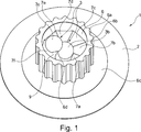
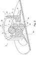
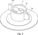
Wie am besten aus
Auf das von dem ersten Bauteil
Der hutkrempenartige Auflageabschnitt
Wie aus den
Wie aus den
Anders ausgedrückt nimmt der von einer Unterseite
Vollständigkeitshalber sei noch der am besten aus
Alternativ zu dem in den
Claims (22)
Priority Applications (4)
| Application Number | Priority Date | Filing Date | Title |
|---|---|---|---|
| DE102014200552.3A DE102014200552B3 (en) | 2014-01-15 | 2014-01-15 | Clamping element and component connection with a clamping element |
| CN201480058768.2A CN105683590B (en) | 2014-01-15 | 2014-12-17 | Clamping element and the element connection device including clamping element |
| PCT/EP2014/078128 WO2015106910A1 (en) | 2014-01-15 | 2014-12-17 | Clamping element and component connection having a clamping element |
| US15/164,065 US10314371B2 (en) | 2014-01-15 | 2016-05-25 | Clamping element and component connection having a clamping element |
Applications Claiming Priority (1)
| Application Number | Priority Date | Filing Date | Title |
|---|---|---|---|
| DE102014200552.3A DE102014200552B3 (en) | 2014-01-15 | 2014-01-15 | Clamping element and component connection with a clamping element |
Publications (1)
| Publication Number | Publication Date |
|---|---|
| DE102014200552B3 true DE102014200552B3 (en) | 2015-01-08 |
Family
ID=52106576
Family Applications (1)
| Application Number | Title | Priority Date | Filing Date |
|---|---|---|---|
| DE102014200552.3A Active DE102014200552B3 (en) | 2014-01-15 | 2014-01-15 | Clamping element and component connection with a clamping element |
Country Status (4)
| Country | Link |
|---|---|
| US (1) | US10314371B2 (en) |
| CN (1) | CN105683590B (en) |
| DE (1) | DE102014200552B3 (en) |
| WO (1) | WO2015106910A1 (en) |
Cited By (1)
| Publication number | Priority date | Publication date | Assignee | Title |
|---|---|---|---|---|
| WO2020200592A1 (en) * | 2019-03-29 | 2020-10-08 | Bayerische Motoren Werke Aktiengesellschaft | Arrangement of a fastening clip on a connecting device which is welded onto a motor vehicle component, and method for producing an arrangement of a fastening clip on a connecting device which is welded onto a vehicle component |
Families Citing this family (2)
| Publication number | Priority date | Publication date | Assignee | Title |
|---|---|---|---|---|
| DE102013211993A1 (en) * | 2013-06-25 | 2015-01-08 | Bayerische Motoren Werke Aktiengesellschaft | A connection between components |
| USD918014S1 (en) * | 2020-08-31 | 2021-05-04 | Walter Eugene Rabon | Portable spa cover lock |
Citations (1)
| Publication number | Priority date | Publication date | Assignee | Title |
|---|---|---|---|---|
| DE8529669U1 (en) * | 1984-10-27 | 1985-11-28 | USM Corp., Farmington, Conn. | Fasteners |
Family Cites Families (24)
| Publication number | Priority date | Publication date | Assignee | Title |
|---|---|---|---|---|
| GB107151A (en) * | 1916-11-02 | 1917-06-21 | Alfred Watkins | An Improved Clamping and Locking Device. |
| US2282360A (en) * | 1940-04-23 | 1942-05-12 | Walter E Horrocks | Lock washer for retaining pins in couplings |
| US3512226A (en) * | 1968-03-12 | 1970-05-19 | Textron Inc | Plastic hook and eye |
| US4166309A (en) * | 1977-03-23 | 1979-09-04 | Dzus Fastener Co., Inc. | Variable height receptacle |
| US4359256A (en) * | 1980-11-14 | 1982-11-16 | The Bendix Corporation | Electrical connector coupling member |
| FR2567085B1 (en) * | 1984-07-06 | 1987-06-26 | Kit Car | DEVICE FOR FIXING OBJECTS TO A WALL AND VAN COMPRISING INTERIOR PARTITIONS FIXED BY SUCH DEVICES |
| US5369856A (en) * | 1993-05-17 | 1994-12-06 | Hauser; Hans | Marine fastener |
| EP0696685B1 (en) * | 1994-08-09 | 1999-10-20 | Arturo Salice S.p.A. | Fastening element |
| DK171783B1 (en) * | 1994-11-14 | 1997-05-26 | Lego As | Overload-proof building element for structural building kits |
| US5897278A (en) * | 1998-02-05 | 1999-04-27 | Southco, Inc. | Turn fastener |
| US6071035A (en) * | 1998-06-01 | 2000-06-06 | Hubbell Incorporated | Interchangeable tool coupling assembly having spring-based locking sleeve |
| US20030231927A1 (en) * | 2002-06-13 | 2003-12-18 | Electronic Eel Manufacturing Company Inc. | Connector for pipe cleaning apparatus |
| JP4234777B1 (en) * | 2008-05-30 | 2009-03-04 | 浩平 中村 | Connection structure |
| WO2010095266A1 (en) * | 2009-02-23 | 2010-08-26 | Ykk株式会社 | Snap button |
| US8024944B2 (en) * | 2009-05-11 | 2011-09-27 | Owens-Brockway Glass Container Inc. | Threadless nut |
| US20110027038A1 (en) * | 2009-07-28 | 2011-02-03 | Pen-Chun YU | Heat sink anchoring apparatus |
| US8757952B2 (en) * | 2009-10-19 | 2014-06-24 | Bowers Ned C | Fastener for securing together two panels |
| US8439593B2 (en) * | 2009-11-10 | 2013-05-14 | Imds Corporation | Quarter turn locking mechanism |
| DE102013213633A1 (en) * | 2013-07-11 | 2015-01-15 | Fidlock Gmbh | closure device |
| WO2015040760A1 (en) * | 2013-09-17 | 2015-03-26 | 株式会社ホンダアクセス | Component-securing device |
| DE102013222484A1 (en) * | 2013-11-06 | 2015-05-07 | Profil Verbindungstechnik Gmbh & Co. Kg | Fastening element for attachment to a component, assembly part comprising the fastening element and method for producing the assembly part |
| DE102014200210B3 (en) * | 2014-01-09 | 2015-05-28 | Bayerische Motoren Werke Aktiengesellschaft | Component assembly with a functional element and method for producing a component composite |
| US9716932B2 (en) * | 2015-06-11 | 2017-07-25 | Oculus Vr, Llc | Detachable audio system for head-mounted displays |
| US10258116B2 (en) * | 2016-03-25 | 2019-04-16 | Yugen Kaisha Houseki-No-Angel | Clasp |
-
2014
- 2014-01-15 DE DE102014200552.3A patent/DE102014200552B3/en active Active
- 2014-12-17 WO PCT/EP2014/078128 patent/WO2015106910A1/en not_active Ceased
- 2014-12-17 CN CN201480058768.2A patent/CN105683590B/en active Active
-
2016
- 2016-05-25 US US15/164,065 patent/US10314371B2/en active Active
Patent Citations (1)
| Publication number | Priority date | Publication date | Assignee | Title |
|---|---|---|---|---|
| DE8529669U1 (en) * | 1984-10-27 | 1985-11-28 | USM Corp., Farmington, Conn. | Fasteners |
Cited By (2)
| Publication number | Priority date | Publication date | Assignee | Title |
|---|---|---|---|---|
| WO2020200592A1 (en) * | 2019-03-29 | 2020-10-08 | Bayerische Motoren Werke Aktiengesellschaft | Arrangement of a fastening clip on a connecting device which is welded onto a motor vehicle component, and method for producing an arrangement of a fastening clip on a connecting device which is welded onto a vehicle component |
| US12281669B2 (en) | 2019-03-29 | 2025-04-22 | Bayerische Motoren Werke Aktiengesellschaft | Arrangement of a fastening clip on a connecting device which is welded onto a motor vehicle component, and method for producing an arrangement of a fastening clip on a connecting device which is welded onto a vehicle component |
Also Published As
| Publication number | Publication date |
|---|---|
| CN105683590A (en) | 2016-06-15 |
| US20160262500A1 (en) | 2016-09-15 |
| CN105683590B (en) | 2018-07-03 |
| US10314371B2 (en) | 2019-06-11 |
| WO2015106910A1 (en) | 2015-07-23 |
Similar Documents
| Publication | Publication Date | Title |
|---|---|---|
| DE102013218649B3 (en) | Clip connection and clip element | |
| EP1961976B1 (en) | Fastening device | |
| EP1626185A1 (en) | Adjusting unit for adjusting the distance between two construction units | |
| DE102012221228A1 (en) | Device for compensating tolerances between two screwed components, has spacer ring that acts in axial direction and is moved to component against restoring force of fastener fixedly connected to base element | |
| EP3649353A1 (en) | Fastening arrangement | |
| DE19921613A1 (en) | Fastener | |
| DE102005032699A1 (en) | fastening device | |
| DE102014200552B3 (en) | Clamping element and component connection with a clamping element | |
| EP2816243B1 (en) | Fastening element | |
| DE19752714C2 (en) | Fastening arrangement for attaching a component to a C-shaped holding rail | |
| DE202011105943U1 (en) | Tolerance compensation device | |
| EP3159180A1 (en) | Roller for moveable objects | |
| WO2014005888A1 (en) | Nut | |
| DE102010019926B4 (en) | Fastening arrangement for detachable fastening of an attachment | |
| EP1600590B1 (en) | Stop buffer | |
| EP3464913A1 (en) | Wrench width adapter for a component which can be screwed into a threaded opening | |
| DE102005029529B4 (en) | Connecting device for fastening components | |
| DE102016209395A1 (en) | Fastening element for tolerance compensation | |
| DE102019213029B4 (en) | Screw nut device | |
| EP2369184A2 (en) | Device with self-actuated compensation of production or installation-related tolerances for resting one component on a second component | |
| DE102005054402B4 (en) | Disc brake, in particular for a commercial vehicle | |
| EP3180521A1 (en) | Clip element, method for producing a component connection, and component connection | |
| WO2004076787A1 (en) | Turnbuckle lock | |
| DE10104041A1 (en) | Fixing device for hinges of motor vehicle doors or flaps comprises a hinge part fixed to the vehicle body by a screw and a clamping sleeve having a through opening for the screw and two lever arms | |
| DE102014207063A1 (en) | Hollow profile with at least two cavity defining wall areas |
Legal Events
| Date | Code | Title | Description |
|---|---|---|---|
| R012 | Request for examination validly filed | ||
| R016 | Response to examination communication | ||
| R018 | Grant decision by examination section/examining division | ||
| R020 | Patent grant now final |