DE102013226552B3 - Mounting device for a rolling bearing - Google Patents
Mounting device for a rolling bearing Download PDFInfo
- Publication number
- DE102013226552B3 DE102013226552B3 DE201310226552 DE102013226552A DE102013226552B3 DE 102013226552 B3 DE102013226552 B3 DE 102013226552B3 DE 201310226552 DE201310226552 DE 201310226552 DE 102013226552 A DE102013226552 A DE 102013226552A DE 102013226552 B3 DE102013226552 B3 DE 102013226552B3
- Authority
- DE
- Germany
- Prior art keywords
- mounting device
- bearing
- ring
- axial
- measuring
- Prior art date
- Legal status (The legal status is an assumption and is not a legal conclusion. Google has not performed a legal analysis and makes no representation as to the accuracy of the status listed.)
- Active
Links
Images
Classifications
-
- F—MECHANICAL ENGINEERING; LIGHTING; HEATING; WEAPONS; BLASTING
- F16—ENGINEERING ELEMENTS AND UNITS; GENERAL MEASURES FOR PRODUCING AND MAINTAINING EFFECTIVE FUNCTIONING OF MACHINES OR INSTALLATIONS; THERMAL INSULATION IN GENERAL
- F16C—SHAFTS; FLEXIBLE SHAFTS; ELEMENTS OR CRANKSHAFT MECHANISMS; ROTARY BODIES OTHER THAN GEARING ELEMENTS; BEARINGS
- F16C35/00—Rigid support of bearing units; Housings, e.g. caps, covers
- F16C35/04—Rigid support of bearing units; Housings, e.g. caps, covers in the case of ball or roller bearings
- F16C35/06—Mounting or dismounting of ball or roller bearings; Fixing them onto shaft or in housing
- F16C35/078—Mounting or dismounting of ball or roller bearings; Fixing them onto shaft or in housing using pressure fluid as mounting aid
-
- B—PERFORMING OPERATIONS; TRANSPORTING
- B25—HAND TOOLS; PORTABLE POWER-DRIVEN TOOLS; MANIPULATORS
- B25B—TOOLS OR BENCH DEVICES NOT OTHERWISE PROVIDED FOR, FOR FASTENING, CONNECTING, DISENGAGING, OR HOLDING
- B25B27/00—Hand tools, specially adapted for fitting together or separating parts or objects whether or not involving some deformation, not otherwise provided for
- B25B27/02—Hand tools, specially adapted for fitting together or separating parts or objects whether or not involving some deformation, not otherwise provided for for connecting objects by press fit or detaching same
- B25B27/06—Hand tools, specially adapted for fitting together or separating parts or objects whether or not involving some deformation, not otherwise provided for for connecting objects by press fit or detaching same inserting or withdrawing sleeves or bearing races
- B25B27/064—Hand tools, specially adapted for fitting together or separating parts or objects whether or not involving some deformation, not otherwise provided for for connecting objects by press fit or detaching same inserting or withdrawing sleeves or bearing races fluid driven
-
- F—MECHANICAL ENGINEERING; LIGHTING; HEATING; WEAPONS; BLASTING
- F16—ENGINEERING ELEMENTS AND UNITS; GENERAL MEASURES FOR PRODUCING AND MAINTAINING EFFECTIVE FUNCTIONING OF MACHINES OR INSTALLATIONS; THERMAL INSULATION IN GENERAL
- F16C—SHAFTS; FLEXIBLE SHAFTS; ELEMENTS OR CRANKSHAFT MECHANISMS; ROTARY BODIES OTHER THAN GEARING ELEMENTS; BEARINGS
- F16C35/00—Rigid support of bearing units; Housings, e.g. caps, covers
- F16C35/04—Rigid support of bearing units; Housings, e.g. caps, covers in the case of ball or roller bearings
- F16C35/06—Mounting or dismounting of ball or roller bearings; Fixing them onto shaft or in housing
- F16C35/063—Fixing them on the shaft
-
- F—MECHANICAL ENGINEERING; LIGHTING; HEATING; WEAPONS; BLASTING
- F16—ENGINEERING ELEMENTS AND UNITS; GENERAL MEASURES FOR PRODUCING AND MAINTAINING EFFECTIVE FUNCTIONING OF MACHINES OR INSTALLATIONS; THERMAL INSULATION IN GENERAL
- F16C—SHAFTS; FLEXIBLE SHAFTS; ELEMENTS OR CRANKSHAFT MECHANISMS; ROTARY BODIES OTHER THAN GEARING ELEMENTS; BEARINGS
- F16C35/00—Rigid support of bearing units; Housings, e.g. caps, covers
- F16C35/04—Rigid support of bearing units; Housings, e.g. caps, covers in the case of ball or roller bearings
- F16C35/06—Mounting or dismounting of ball or roller bearings; Fixing them onto shaft or in housing
- F16C35/067—Fixing them in a housing
-
- F—MECHANICAL ENGINEERING; LIGHTING; HEATING; WEAPONS; BLASTING
- F16—ENGINEERING ELEMENTS AND UNITS; GENERAL MEASURES FOR PRODUCING AND MAINTAINING EFFECTIVE FUNCTIONING OF MACHINES OR INSTALLATIONS; THERMAL INSULATION IN GENERAL
- F16C—SHAFTS; FLEXIBLE SHAFTS; ELEMENTS OR CRANKSHAFT MECHANISMS; ROTARY BODIES OTHER THAN GEARING ELEMENTS; BEARINGS
- F16C2233/00—Monitoring condition, e.g. temperature, load, vibration
Landscapes
- Engineering & Computer Science (AREA)
- General Engineering & Computer Science (AREA)
- Mechanical Engineering (AREA)
- Mounting Of Bearings Or Others (AREA)
- Support Of The Bearing (AREA)
Abstract
Die Erfindung betrifft eine Montagevorrichtung (1) für ein Wälzlager (2) mit einem Innenring (3) und einem Außenring (4), wobei die Montagevorrichtung (1) einen Grundkörper (5) aufweist, der auf einem einen Lagerring (3) tragenden ersten Bauteil (6), insbesondere einer Welle, axial (a) festlegbar ist, wobei der Grundkörper (5) ein in axiale Richtung (a) verschiebbares Element (7), insbesondere einen Kolben, aufweist, wobei mit dem verschiebbaren Element (7) ein Lagerring (3) relativ zum ersten Bauteil (6) in axialer Richtung (a) verschoben werden kann. Um einen axialen Versatz und damit axiale Verspannungen zwischen Innen- und Außenring zu vermeiden, sieht die Erfindung vor, dass die Montagevorrichtung (1) weiter aufweist: ein erstes Messelement (8) zur Messung der axialen Verschiebung zwischen dem Grundkörper (5) und dem Innenring (3) und ein zweites Messelement (9) zur Messung der axialen Verschiebung zwischen dem Grundkörper (5) und dem Außenring (4).The invention relates to a mounting device (1) for a rolling bearing (2) with an inner ring (3) and an outer ring (4), wherein the mounting device (1) has a base body (5) on a first bearing a bearing ring (3) Component (6), in particular a shaft, axially (a) can be fixed, wherein the base body (5) in the axial direction (a) displaceable element (7), in particular a piston, wherein with the displaceable element (7) a Bearing ring (3) relative to the first component (6) in the axial direction (a) can be moved. In order to avoid an axial offset and thus axial tension between inner and outer ring, the invention provides that the mounting device (1) further comprises: a first measuring element (8) for measuring the axial displacement between the base body (5) and the inner ring (3) and a second measuring element (9) for measuring the axial displacement between the base body (5) and the outer ring (4).
Description
Die Erfindung betrifft eine Montagevorrichtung für ein Wälzlager mit einem Innenring und einem Außenring, wobei die Montagevorrichtung einen Grundkörper aufweist, der auf einem einen Lagerring tragenden ersten Bauteil, insbesondere einer Welle, axial festlegbar ist, wobei der Grundkörper ein in axiale Richtung verschiebbares Element, insbesondere einen Kolben, aufweist, wobei mit dem verschiebbaren Element ein Lagerring relativ zum ersten Bauteil in axialer Richtung verschoben werden kann.The invention relates to a mounting device for a rolling bearing with an inner ring and an outer ring, wherein the mounting device has a base body which is axially fixable on a bearing member bearing a first component, in particular a shaft, wherein the base body an axially displaceable element, in particular a piston, wherein with the displaceable element, a bearing ring can be moved relative to the first component in the axial direction.
Eine gattungsgemäße Vorrichtung ist aus der
Bei der Montage von Wälzlagern werden diese beispielsweise auf eine Welle axial aufgeschoben, d. h. der Innenring des Wälzlagers wird axial auf die Welle aufgeschoben; der Außenring wird gleichzeitig in eine Gehäusebohrung eingeschoben. Hierfür sind gattungsgemäße Montagevorrichtungen bekannt, die auch als „Hydraulikmuttern“ bezeichnet werden. Demgemäß wird ein Gewindeabschnitt auf der Welle fixiert und mittels eines hydraulisch beweglichen Elements (Kolben) der Lagerinnenring auf die Welle aufgeschoben.When mounting bearings they are pushed axially, for example, on a shaft, d. H. the inner ring of the rolling bearing is pushed axially onto the shaft; the outer ring is simultaneously inserted into a housing bore. For this purpose, generic mounting devices are known, which are also referred to as "hydraulic nuts". Accordingly, a threaded portion is fixed on the shaft and pushed by means of a hydraulically movable element (piston) of the bearing inner ring on the shaft.
Für die Montage von Wälzlagern kommt beispielsweise die Drive-Up-Methode zur Anwendung. Dieses Verfahren eignet sich bevorzugt für den Einbau von Pendelrollenlagern und Toroidalrollenlagern mit kegeliger Bohrung auf kegeligem Sitz. Es ermöglicht eine sichere und einfache Bestimmung der Ausgangslage eines Lagers, von der aus die axiale Verschiebung beim Aufschieben auf die Welle gemessen wird. Die hierbei verwendete Montagevorrichtung ist zu diesem Zweck mit einer Messuhr versehen. Weiterhin ist ein Manometer zur Messung des hydraulischen Montagedrucks vorhanden, das auf die Montagebedingungen abgestimmt ist; es ist auf einer Ölpumpe montiert. For example, the drive-up method is used for mounting rolling bearings. This method is particularly suitable for the installation of spherical roller bearings and Toroidalrollenlagern with tapered bore on conical seat. It allows a safe and easy determination of the initial position of a bearing from which the axial displacement is measured when pushed onto the shaft. The mounting device used in this case is provided for this purpose with a dial gauge. Furthermore, a pressure gauge for measuring the hydraulic assembly pressure is available, which is tailored to the mounting conditions; it is mounted on an oil pump.
Für jedes zu montierende Lager sind Richtwerte für den erforderlichen Druck in der Montagevorrichtung (Hydraulikmutter) verfügbar. Das genannte Montageverfahren reduziert vorteilhaft die Lagerluftmessung mit Fühlerlehren auf ein Minimum. Die Montagezeiten sind relativ kurz. Es ist ein korrekter Einbau des Lagers sichergestellt, was teilweise den Einbau von abgedichteten Lagern erst möglich macht. For each bearing to be mounted, reference values are available for the required pressure in the mounting device (hydraulic nut). The aforementioned assembly method advantageously reduces the bearing air measurement with feeler gauges to a minimum. The installation times are relatively short. It is ensured a correct installation of the bearing, which partially makes the installation of sealed bearings possible.
Beim Drive-Up-Verfahren werden zunächst die Einbauverhältnisse hinsichtlich der Zahl der Gleitflächen beim Einbau überprüft. Diese werden mit einem dünnen Öl bestrichen und das Lager auf den Wellenzapfen bzw. die Spannhülse aufgesetzt. Die Montagevorrichtung (Hydraulikmutter) wird bis zur festen Anlage am Lager auf das Wellen- oder Hülsengewinde aufgeschraubt und eine geeignete Ölpumpe angeschlossen. Der Öldruck kann mit dem Manometer auf der ausgewählten Pumpe überwacht werden. Das Lager wird mittels der Montagevorrichtung (Hydraulikmutter) um den erforderlichen Abstand über die Kegelfläche getrieben. Der axiale Verschiebeweg wird durch eine Messuhr kontrolliert. Normalerweise ist das Lager nun mit einer geeigneten Überdeckung an der Welle und einer passenden Restlagerluft montiert. The drive-up procedure first checks the installation conditions with regard to the number of sliding surfaces during installation. These are coated with a thin oil and put the bearing on the shaft journal or the clamping sleeve. The mounting device (hydraulic nut) is screwed to the fixed bearing on the shaft or sleeve thread and connected to a suitable oil pump. The oil pressure can be monitored with the manometer on the selected pump. The bearing is driven by the required distance over the conical surface by means of the mounting device (hydraulic nut). The axial displacement is controlled by a dial indicator. Normally, the bearing is now mounted with a suitable overlap on the shaft and a matching residual bearing air.
Problematisch ist dabei folgendes: Bei der Montage mit der Drive-Up-Methode kann – insbesondere bei Einbausituationen, in denen der Lageraußenring mit fester Passung im Gehäuse sitzt – während des axialen Verschiebens des Lagerinnenringes bei gleichzeitigem Stehenbleiben des Lageraußenringes ein axialer Versatz der beiden Ringe zueinander auftreten. Insbesondere bei Pendelrollenlagern kann dies zu einer axialen Vorspannung führen, die ggf. bereits bei der Montage Vorschädigungen im Lager hervorrufen kann. Lageraußenringe werden zwar nach der Montage mechanisch, beispielsweise mit einem Hammer, nachgesetzt. Da kann der Schaden aber bereits aufgetreten sein.The problem is the following: When mounting with the drive-up method can - especially in installation situations in which the bearing outer ring with a tight fit sitting in the housing - during the axial displacement of the bearing inner ring while keeping the bearing outer ring, an axial offset of the two rings to each other occur. In particular, with spherical roller bearings this can lead to an axial preload, which may possibly already cause damage during assembly in the camp. Although bearing outer rings are mechanically set after installation, for example with a hammer. Since the damage may already have occurred.
Der Erfindung liegt daher die Aufgabe zugrunde, eine gattungsgemäße Montagevorrichtung für ein Wälzlager so fortzubilden, dass ein sicherer und möglichst vorspannungsfreier Einbau des Lagers möglich wird, auch wenn beim Einbau nur einer der Lagerringe mit einer axialen Fügekraft beaufschlagt wird. Demgemäß wird mit der Montagevorrichtung angestrebt, eine Montage in der Weise vorzunehmen, dass ein axialer Versatz und damit eine axiale Verspannungen zwischen Innen- und Außenring vermieden werden kann. The invention is therefore the object of a generic mounting device for a rolling bearing so educate that a safe and possible vorspannungsfreier installation of the bearing is possible, even if only one of the bearing rings is acted upon during installation with an axial joining force. Accordingly, it is desirable with the mounting device to carry out a mounting in such a way that an axial offset and thus an axial tension between the inner and outer ring can be avoided.
Die Lösung dieser Aufgabe durch die Erfindung ist dadurch gekennzeichnet, dass die Montagevorrichtung aufweist:
- – ein erstes Messelement zur Messung der axialen Verschiebung zwischen dem Grundkörper und dem Innenring,
- – ein zweites Messelement zur Messung der axialen Verschiebung zwischen dem Grundkörper und dem Außenring und
- – Verstellmittel, mit denen der Lagerring, der mit dem verschiebbaren Element nicht axial verschoben werden kann, relativ zum Grundkörper in axiale Richtung verschoben werden kann, wobei die Verstellmittel mindestens eine Schraube umfassen, die in einen Gewindeabschnitt im Grundkörper eingeschraubt ist und die mit ihrem axialen Ende auf den zu verschiebenden Lagerring drückt.
- A first measuring element for measuring the axial displacement between the main body and the inner ring,
- - A second measuring element for measuring the axial displacement between the main body and the outer ring and
- - Adjustment means by which the bearing ring, which can not be moved axially with the displaceable element, can be displaced in the axial direction relative to the base body, wherein the adjusting means comprise at least one screw which is screwed into a threaded portion in the base body and with its axial Press end on the bearing ring to be moved.
Bevorzugt sind dabei allerdings mehrere Schrauben um den Umfang des Grundkörpers angeordnet. However, several screws are preferably arranged around the circumference of the base body.
Der Grundkörper kann – bei hinreichender radialer Erstreckung – einstückig ausgebildet sein und das verschiebbare Element sowie beide Messelemente tragen.The basic body can - with sufficient radial extension - be integrally formed and carry the displaceable element and both measuring elements.
Es ist allerdings alternativ auch möglich, dass der Grundkörper zweiteilig ausgebildet ist, wobei ein erster Teil das verschiebbare Element und ein Messelement trägt und wobei ein zweiter Teil das andere Messelement trägt. Der zweite Teil des Grundkörpers kann dabei als Ring ausgebildet sein, der auf dem oder an dem ersten Teil des Grundkörpers angesetzt und mit diesem verbunden, insbesondere verschweißt, ist. However, it is alternatively also possible that the base body is formed in two parts, wherein a first part carries the displaceable element and a measuring element and wherein a second part carries the other measuring element. The second part of the body can be formed as a ring, which is attached to the or on the first part of the body and connected thereto, in particular welded, is.
Die Messelemente sind bevorzugt als Messuhren ausgebildet. Sie weisen bevorzugt ein Rückstellelement zur Nullung (Rückstellung auf den Ausgangswert ‚Null‘) der Messuhr auf. The measuring elements are preferably designed as gauges. They preferably have a reset element for zeroing (return to the initial value 'zero') of the dial gauge.
Die Messelemente sind bevorzugt mittels einer Schraubverbindung am Grundkörper befestigt. The measuring elements are preferably fastened by means of a screw connection to the base body.
Die Erfindung schlägt demgemäß eine Modifikation der bestehenden Montagevorrichtung (Hydraulikmuttern) derart vor, dass sie zur Aufnahme einer zweiten Messuhr tauglich bzw. mit einer solchen ausgestattet ist, um die axiale Relativposition zwischen Innen- und Außenring des Lagers während der Montage, insbesondere während der Drive-Up-Montage, bestimmen zu können. Besagte Modifikation der Hydraulikmutter erfolgt also zur Erfassung der axialen Relativposition von Lageraußen- und -innenring. The invention accordingly proposes a modification of the existing mounting device (hydraulic nuts) such that it is suitable for receiving a second dial gauge or equipped with such a to the axial relative position between the inner and outer ring of the bearing during assembly, in particular during the drive -Up assembly, to be able to determine. Said modification of the hydraulic nut thus takes place for detecting the axial relative position of Lageraußen- and inner ring.
Bei ausreichendem Querschnitt der Hydraulikmutter im Verhältnis zur Projektionsfläche des Lagers kann also wie erläutert ein einteiliger Aufbau des Grundkörpers der Montagevorrichtung vorgesehen werden. Hier können dann in eine bestehende Montagevorrichtung zusätzliche Gewindebohrungen eingearbeitet werden, um auf der radialen Höhe des Außenrings eine zweite Messuhr anbringen zu können und auch Mittel zur axialen Verschiebung des Außenrings (beispielsweise durch Druckschrauben).With sufficient cross-section of the hydraulic nut in relation to the projection surface of the bearing can thus be provided as explained a one-piece construction of the base body of the mounting device. Here additional threaded holes can then be incorporated into an existing mounting device in order to attach a second dial gauge on the radial height of the outer ring and also means for axial displacement of the outer ring (for example, by pressure screws).
Bei zu geringem Querschnitt der Hydraulikmutter im Verhältnis zur Projektionsfläche des Lagers kann eine Adaption dahingehend erfolgen, dass ein Anbauteil an den Grundkörper der Hydraulikmutter angeordnet wird. In dieses Anbauteil, welches den Querschnitt bzw. die Projektionsfläche vergrößert, sind dann Gewinde auf der radialen Höhe des Außenringes eingebracht, um die zweite Messuhr anbringen zu können, gleichermaßen die Mittel zum axialen Bewegen des Außenringes (beispielsweise Druckschrauben).If the cross-section of the hydraulic nut is too small in relation to the projection surface of the bearing, an adaptation can be made such that an attachment is arranged on the main body of the hydraulic nut. In this attachment, which increases the cross-section or the projection surface, then threads are introduced at the radial height of the outer ring to attach the second dial can, equally the means for axially moving the outer ring (for example, pressure screws).
Die Montagevorrichtung (Hydraulikmutter) wird zwecks Montage des Wälzlagers auf ein Gewinde der Welle aufgeschraubt, bis axialer Kontakt des Kolbens zum Innenring besteht. Dann werden die beiden Messuhren angebracht. Die eine hat axialen Kontakt zum beweglichen Kolben der Hydraulikmutter, die zweite zum Lageraußenring. Beide Messuhren werden genullt. Während des Montagevorganges mit der Hydraulikmutter zeigt die Messuhr am Kolben bzw. am Innenring den axialen Weg an, um den der Innenring bewegt wird. In geeigneten Abständen, abhängig von der Größe der Axialluft im Lager, kann der Außenring entsprechend der gemessenen axialen Bewegung des Innenringes und der gemessenen axialen Bewegung des Außenrings axial nachgestellt werden, wozu die genannten Verstellmittel dienen. The mounting device (hydraulic nut) is screwed for the purpose of mounting the roller bearing on a thread of the shaft until there is axial contact of the piston to the inner ring. Then the two dial gauges are attached. One has axial contact with the movable piston of the hydraulic nut, the second with the bearing outer ring. Both dial gauges are zeroed. During the assembly process with the hydraulic nut, the dial indicator on the piston or on the inner ring indicates the axial path around which the inner ring is moved. At suitable intervals, depending on the size of the axial clearance in the bearing, the outer ring can be readjusted axially in accordance with the measured axial movement of the inner ring and the measured axial movement of the outer ring, to which serve the said adjusting means.
Durch das axiale Nachführen des Außenringes im Verhältnis zum Innenring kann axialer Versatz und somit eine axiale Vorspannung und damit schließlich eine gegebenenfalls auftretende Vorschädigung im Lager vermieden werden. Due to the axial tracking of the outer ring in relation to the inner ring axial offset and thus an axial bias and thus eventually an optionally occurring pre-damage can be avoided in the camp.
Nach Abschluss des Montagevorganges sind die beiden Lagerringe bereits axial zueinander ausgerichtet. Es ist kein weiteres zusätzliches Nachstellen nötig.After completion of the assembly process, the two bearing rings are already aligned axially to each other. There is no further additional adjustment necessary.
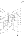
In der Zeichnung ist ein Ausführungsbeispiel der Erfindung dargestellt. Die einzige Figur zeigt im Radialschnitt eine Montagevorrichtung, mit der ein Wälzlager zwischen ein Gehäuse und eine Welle montiert wird. In the drawing, an embodiment of the invention is shown. The single FIGURE shows a radial section of a mounting device with which a rolling bearing between a housing and a shaft is mounted.
In der Figur ist ein Wälzlager
Zum Montieren des Wälzlagers
Zentrales Element der Montagevorrichtung
Problematisch ist, dass insbesondere bei Presssitz zwischen der außenliegenden Sitzfläche des Außenrings
Um dies zu verhindern, ist folgendes vorgesehen:
Am Grundkörper
At the
Durch simultanes Ablesen beider Messuhren
Die Druckschrauben
BezugszeichenlisteLIST OF REFERENCE NUMBERS
- 11
- Montagevorrichtung mounter
- 22
- Wälzlager roller bearing
- 33
- Innenring inner ring
- 44
- Außenring outer ring
- 55
- Grundkörper body
- 5‘5 '
- erster Teil des Grundkörpers first part of the body
- 5‘‘5 ''
- zweiter Teil des Grundkörpers second part of the body
- 66
- erstes Bauteil (Welle) first component (shaft)
- 77
- verschiebbares Element (Kolben) sliding element (piston)
- 88th
- erstes Messelement first measuring element
- 99
- zweites Messelement second measuring element
- 1010
- Verstellmittel (Druckschraube) Adjusting means (pressure screw)
- 1111
- Gewindeabschnitt threaded portion
- 1212
- zweites Bauteil (Gehäuse) second component (housing)
- 1313
- Gehäusebohrung housing bore
- 1414
- Verschweißung welding
- 1515
- Zylinderraum cylinder space
- 1616
- Gewinde thread
- 1717
- Wellensitz shaft seat
- aa
- axiale Richtung axial direction
Claims (8)
Priority Applications (1)
| Application Number | Priority Date | Filing Date | Title |
|---|---|---|---|
| DE201310226552 DE102013226552B3 (en) | 2013-12-19 | 2013-12-19 | Mounting device for a rolling bearing |
Applications Claiming Priority (1)
| Application Number | Priority Date | Filing Date | Title |
|---|---|---|---|
| DE201310226552 DE102013226552B3 (en) | 2013-12-19 | 2013-12-19 | Mounting device for a rolling bearing |
Publications (1)
| Publication Number | Publication Date |
|---|---|
| DE102013226552B3 true DE102013226552B3 (en) | 2015-05-13 |
Family
ID=52991137
Family Applications (1)
| Application Number | Title | Priority Date | Filing Date |
|---|---|---|---|
| DE201310226552 Active DE102013226552B3 (en) | 2013-12-19 | 2013-12-19 | Mounting device for a rolling bearing |
Country Status (1)
| Country | Link |
|---|---|
| DE (1) | DE102013226552B3 (en) |
Cited By (6)
| Publication number | Priority date | Publication date | Assignee | Title |
|---|---|---|---|---|
| CN109139717A (en) * | 2018-10-29 | 2019-01-04 | 思进智能成形装备股份有限公司 | A kind of bearing installation method of cold headers |
| DE102018102199A1 (en) | 2018-02-01 | 2019-08-01 | Schaeffler Technologies AG & Co. KG | Mounting device and assembly method for mounting a component on a shaft |
| WO2022017720A1 (en) | 2020-07-24 | 2022-01-27 | Sew-Eurodrive Gmbh & Co. Kg | Method and system for producing a gear unit |
| CN117553072A (en) * | 2024-01-10 | 2024-02-13 | 洛阳洛轴精密轴承有限公司 | Aligning sliding-rolling composite bearing and performance testing device thereof |
| US20240410419A1 (en) * | 2023-06-09 | 2024-12-12 | Nordex Energy Se & Co. Kg | Bearing arrangement for a rotating component of a wind turbine |
| US20240410420A1 (en) * | 2023-06-09 | 2024-12-12 | Nordex Energy Se & Co. Kg | Bearing arrangement for a rotating component of a wind turbine |
Citations (6)
| Publication number | Priority date | Publication date | Assignee | Title |
|---|---|---|---|---|
| DE969991C (en) * | 1954-07-03 | 1958-08-07 | Saab Scania Ab | Mandrel for installing roller bearings |
| DE69514046T2 (en) * | 1994-06-21 | 2000-08-03 | Aktiebolaget Skf, Goeteborg/Gotenburg | Procedure for mounting bearings with a tapered bore |
| DE69535255T2 (en) * | 1994-12-23 | 2007-05-16 | Skf Maintenance Products B.V. | Hydraulic nut for mounting conical objects |
| DE102007005160A1 (en) * | 2006-01-27 | 2007-08-02 | Rode, John E. | Method, apparatus and nut for preloading a bearing |
| DE102010014771A1 (en) * | 2010-04-13 | 2011-10-13 | Schaeffler Technologies Gmbh & Co. Kg | Double-row tapered roller bearing for use in wind power plant, comprises outer bearing ring, inner bearing ring, and multiple rollers arranged between two bearing rings next to each other in two rows |
| DE102010019070A1 (en) * | 2010-05-03 | 2011-11-03 | Schaeffler Technologies Gmbh & Co. Kg | Adjustment device for bearing assembly, has annular pressure chamber, where pressure medium causes defined height compensation or defined bearing prestress of bearing assembly in conjunction with ring-shaped element |
-
2013
- 2013-12-19 DE DE201310226552 patent/DE102013226552B3/en active Active
Patent Citations (6)
| Publication number | Priority date | Publication date | Assignee | Title |
|---|---|---|---|---|
| DE969991C (en) * | 1954-07-03 | 1958-08-07 | Saab Scania Ab | Mandrel for installing roller bearings |
| DE69514046T2 (en) * | 1994-06-21 | 2000-08-03 | Aktiebolaget Skf, Goeteborg/Gotenburg | Procedure for mounting bearings with a tapered bore |
| DE69535255T2 (en) * | 1994-12-23 | 2007-05-16 | Skf Maintenance Products B.V. | Hydraulic nut for mounting conical objects |
| DE102007005160A1 (en) * | 2006-01-27 | 2007-08-02 | Rode, John E. | Method, apparatus and nut for preloading a bearing |
| DE102010014771A1 (en) * | 2010-04-13 | 2011-10-13 | Schaeffler Technologies Gmbh & Co. Kg | Double-row tapered roller bearing for use in wind power plant, comprises outer bearing ring, inner bearing ring, and multiple rollers arranged between two bearing rings next to each other in two rows |
| DE102010019070A1 (en) * | 2010-05-03 | 2011-11-03 | Schaeffler Technologies Gmbh & Co. Kg | Adjustment device for bearing assembly, has annular pressure chamber, where pressure medium causes defined height compensation or defined bearing prestress of bearing assembly in conjunction with ring-shaped element |
Cited By (13)
| Publication number | Priority date | Publication date | Assignee | Title |
|---|---|---|---|---|
| DE102018102199A1 (en) | 2018-02-01 | 2019-08-01 | Schaeffler Technologies AG & Co. KG | Mounting device and assembly method for mounting a component on a shaft |
| WO2019149313A1 (en) | 2018-02-01 | 2019-08-08 | Schaeffler Technologies AG & Co. KG | Mounting device and mounting method for mounting a component on a shaft |
| DE102018102199B4 (en) | 2018-02-01 | 2020-07-09 | Schaeffler Technologies AG & Co. KG | Mounting device and mounting method for mounting a component on a shaft |
| CN109139717A (en) * | 2018-10-29 | 2019-01-04 | 思进智能成形装备股份有限公司 | A kind of bearing installation method of cold headers |
| CN115702295A (en) * | 2020-07-24 | 2023-02-14 | 索尤若驱动有限及两合公司 | Method and system for manufacturing a retarder |
| DE102021003240A1 (en) | 2020-07-24 | 2022-01-27 | Sew-Eurodrive Gmbh & Co Kg | Method and system for manufacturing a gearbox |
| WO2022017720A1 (en) | 2020-07-24 | 2022-01-27 | Sew-Eurodrive Gmbh & Co. Kg | Method and system for producing a gear unit |
| US11927220B2 (en) | 2020-07-24 | 2024-03-12 | Sew-Eurodrive Gmbh & Co. Kg | Method and system for producing a gear unit |
| CN115702295B (en) * | 2020-07-24 | 2025-07-11 | 索尤若驱动有限及两合公司 | Method and system for manufacturing a reducer |
| US20240410419A1 (en) * | 2023-06-09 | 2024-12-12 | Nordex Energy Se & Co. Kg | Bearing arrangement for a rotating component of a wind turbine |
| US20240410420A1 (en) * | 2023-06-09 | 2024-12-12 | Nordex Energy Se & Co. Kg | Bearing arrangement for a rotating component of a wind turbine |
| CN117553072A (en) * | 2024-01-10 | 2024-02-13 | 洛阳洛轴精密轴承有限公司 | Aligning sliding-rolling composite bearing and performance testing device thereof |
| CN117553072B (en) * | 2024-01-10 | 2024-04-02 | 洛阳洛轴精密轴承有限公司 | Aligning sliding-rolling composite bearing and performance testing device thereof |
Similar Documents
| Publication | Publication Date | Title |
|---|---|---|
| DE102013226552B3 (en) | Mounting device for a rolling bearing | |
| DE2032111C3 (en) | Device for adjusting the axial play or the axial preload of angular contact bearings and adjusting rings for this device | |
| DE69535255T2 (en) | Hydraulic nut for mounting conical objects | |
| DE102015218993B3 (en) | Bearing arrangement with a strain sensor device | |
| DE112019000578B4 (en) | FLUID LEAKAGE DETECTION DEVICE AND RECIPROCATING FLUID PRESSURE DEVICE | |
| DE10256855A1 (en) | Procedure for assembling a double row tapered roller bearing | |
| EP2050975A1 (en) | Device for a friction coupling of two coaxial components | |
| DE2538438C2 (en) | Gas-tight thread connection of pipes | |
| DE102014214999B4 (en) | Bearing arrangement with preload | |
| CH701086B1 (en) | Apparatus for frictionally coupling two coaxial components. | |
| EP4232711A1 (en) | Gearing having a housing and a shaft unit | |
| EP3403758B1 (en) | Adjustable attachment adapter | |
| DE112016000372B4 (en) | Fluid pressure cylinder | |
| EP3403749B1 (en) | Counterbearing for a machining spindle of a machine tool and method of clamping a counterbearing | |
| DE3322861C2 (en) | Screw connection that absorbs transverse forces, especially for clamping the split crankcase of an engine together | |
| EP3489534A1 (en) | Bearing pretensioning device for a large-size bearing unit as well as large-size bearing unit | |
| DE102015012705B4 (en) | Clamping unit for rolling bearings on axles and shafts | |
| DE4013896C1 (en) | Pre-tension adjuster for ball bearings - has end of sleeve bearing against fixed end-stop in housing | |
| DE102015220013A1 (en) | bearing arrangement | |
| DE10316005A1 (en) | Procedure for adjusting the clearance or preload of a bearing | |
| DE914211C (en) | Piston pin bearing | |
| DE112006000547B4 (en) | Hydraulic cylinder piston | |
| AT511170B1 (en) | DEVICE AND METHOD FOR ADJUSTING THE AXIAL POSITION OF AN AXIAL STORAGE OF AN AXLE RELATIVE TO A REFERENCE COMPONENT | |
| DE102005055822B4 (en) | sleeve assembly | |
| DE102023212174A1 (en) | Apparatus and method for mounting a bearing to a seat. |
Legal Events
| Date | Code | Title | Description |
|---|---|---|---|
| R012 | Request for examination validly filed | ||
| R016 | Response to examination communication | ||
| R018 | Grant decision by examination section/examining division | ||
| R020 | Patent grant now final |