EP3403758B1 - Adjustable attachment adapter - Google Patents
Adjustable attachment adapter Download PDFInfo
- Publication number
- EP3403758B1 EP3403758B1 EP18000436.8A EP18000436A EP3403758B1 EP 3403758 B1 EP3403758 B1 EP 3403758B1 EP 18000436 A EP18000436 A EP 18000436A EP 3403758 B1 EP3403758 B1 EP 3403758B1
- Authority
- EP
- European Patent Office
- Prior art keywords
- clamping
- ring
- braking
- bending plate
- screw
- Prior art date
- Legal status (The legal status is an assumption and is not a legal conclusion. Google has not performed a legal analysis and makes no representation as to the accuracy of the status listed.)
- Active
Links
Images


Classifications
-
- B—PERFORMING OPERATIONS; TRANSPORTING
- B23—MACHINE TOOLS; METAL-WORKING NOT OTHERWISE PROVIDED FOR
- B23Q—DETAILS, COMPONENTS, OR ACCESSORIES FOR MACHINE TOOLS, e.g. ARRANGEMENTS FOR COPYING OR CONTROLLING; MACHINE TOOLS IN GENERAL CHARACTERISED BY THE CONSTRUCTION OF PARTICULAR DETAILS OR COMPONENTS; COMBINATIONS OR ASSOCIATIONS OF METAL-WORKING MACHINES, NOT DIRECTED TO A PARTICULAR RESULT
- B23Q16/00—Equipment for precise positioning of tool or work into particular locations not otherwise provided for
- B23Q16/02—Indexing equipment
- B23Q16/08—Indexing equipment having means for clamping the relatively movable parts together in the indexed position
- B23Q16/10—Rotary indexing
- B23Q16/105—Rotary indexing clamping with a disc brake
-
- F—MECHANICAL ENGINEERING; LIGHTING; HEATING; WEAPONS; BLASTING
- F16—ENGINEERING ELEMENTS AND UNITS; GENERAL MEASURES FOR PRODUCING AND MAINTAINING EFFECTIVE FUNCTIONING OF MACHINES OR INSTALLATIONS; THERMAL INSULATION IN GENERAL
- F16D—COUPLINGS FOR TRANSMITTING ROTATION; CLUTCHES; BRAKES
- F16D2121/00—Type of actuator operation force
- F16D2121/02—Fluid pressure
- F16D2121/12—Fluid pressure for releasing a normally applied brake, the type of actuator being irrelevant or not provided for in groups F16D2121/04 - F16D2121/10
-
- F—MECHANICAL ENGINEERING; LIGHTING; HEATING; WEAPONS; BLASTING
- F16—ENGINEERING ELEMENTS AND UNITS; GENERAL MEASURES FOR PRODUCING AND MAINTAINING EFFECTIVE FUNCTIONING OF MACHINES OR INSTALLATIONS; THERMAL INSULATION IN GENERAL
- F16D—COUPLINGS FOR TRANSMITTING ROTATION; CLUTCHES; BRAKES
- F16D55/00—Brakes with substantially-radial braking surfaces pressed together in axial direction, e.g. disc brakes
- F16D55/02—Brakes with substantially-radial braking surfaces pressed together in axial direction, e.g. disc brakes with axially-movable discs or pads pressed against axially-located rotating members
- F16D55/04—Brakes with substantially-radial braking surfaces pressed together in axial direction, e.g. disc brakes with axially-movable discs or pads pressed against axially-located rotating members by moving discs or pads away from one another against radial walls of drums or cylinders
- F16D55/14—Brakes with substantially-radial braking surfaces pressed together in axial direction, e.g. disc brakes with axially-movable discs or pads pressed against axially-located rotating members by moving discs or pads away from one another against radial walls of drums or cylinders with self-tightening action, e.g. by means of coacting helical surfaces or balls and inclined surfaces
- F16D55/18—Brakes actuated by a fluid-pressure device arranged in or on the brake
-
- F—MECHANICAL ENGINEERING; LIGHTING; HEATING; WEAPONS; BLASTING
- F16—ENGINEERING ELEMENTS AND UNITS; GENERAL MEASURES FOR PRODUCING AND MAINTAINING EFFECTIVE FUNCTIONING OF MACHINES OR INSTALLATIONS; THERMAL INSULATION IN GENERAL
- F16D—COUPLINGS FOR TRANSMITTING ROTATION; CLUTCHES; BRAKES
- F16D55/00—Brakes with substantially-radial braking surfaces pressed together in axial direction, e.g. disc brakes
- F16D55/02—Brakes with substantially-radial braking surfaces pressed together in axial direction, e.g. disc brakes with axially-movable discs or pads pressed against axially-located rotating members
- F16D55/22—Brakes with substantially-radial braking surfaces pressed together in axial direction, e.g. disc brakes with axially-movable discs or pads pressed against axially-located rotating members by clamping an axially-located rotating disc between movable braking members, e.g. movable brake discs or brake pads
- F16D55/224—Brakes with substantially-radial braking surfaces pressed together in axial direction, e.g. disc brakes with axially-movable discs or pads pressed against axially-located rotating members by clamping an axially-located rotating disc between movable braking members, e.g. movable brake discs or brake pads with a common actuating member for the braking members
- F16D55/2245—Brakes with substantially-radial braking surfaces pressed together in axial direction, e.g. disc brakes with axially-movable discs or pads pressed against axially-located rotating members by clamping an axially-located rotating disc between movable braking members, e.g. movable brake discs or brake pads with a common actuating member for the braking members in which the common actuating member acts on two levers carrying the braking members, e.g. tong-type brakes
-
- F—MECHANICAL ENGINEERING; LIGHTING; HEATING; WEAPONS; BLASTING
- F16—ENGINEERING ELEMENTS AND UNITS; GENERAL MEASURES FOR PRODUCING AND MAINTAINING EFFECTIVE FUNCTIONING OF MACHINES OR INSTALLATIONS; THERMAL INSULATION IN GENERAL
- F16D—COUPLINGS FOR TRANSMITTING ROTATION; CLUTCHES; BRAKES
- F16D65/00—Parts or details
- F16D65/14—Actuating mechanisms for brakes; Means for initiating operation at a predetermined position
- F16D65/16—Actuating mechanisms for brakes; Means for initiating operation at a predetermined position arranged in or on the brake
- F16D65/22—Actuating mechanisms for brakes; Means for initiating operation at a predetermined position arranged in or on the brake adapted for pressing members apart, e.g. for drum brakes
Definitions
- the invention relates to a braking and / or clamping device for a shaft that is guided relative to a base body, with an actuation assembly and with a shaft connection assembly.
- Braking and / or clamping devices for shafts are known in which, for example, ten sliding wedge gears acting on the friction clamp are arranged around the shaft.
- the sliding wedges are adjusted by means of pneumatic cylinders in order to press the individual brake shoes against the shaft. This construction takes up a lot of space and acts directly on the shaft.
- the EP 1 228 321 B1 describes a clamping and / or braking device for clamping and / or braking a shaft.
- the shaft is surrounded by a basic body.
- the base body comprises an outer ring, an inner ring and two flat rim-like walls arranged between the rings.
- the rings and the walls enclose a pressure chamber.
- the pressure chamber When the pressure chamber is ventilated, the inner ring is clamped radially on the shaft. If the pressure chamber is filled with a pressure medium, the walls bulge, which releases the inner ring of the shaft.
- the problem underlying the present invention is to develop such a braking and / or clamping device which, even with a large diameter, has a small overall width, consists of a few components and, in addition, is adjustable, simple, safe and requires no maintenance.
- the actuation assembly has a gap housing which has a mounting zone and a bending zone which can be elastically bulged in some areas and has two bending plates separated by a gap.
- the bending plates each have pliers jaws with friction surfaces in two opposing clamping zones, the surface normals of which face inwards.
- a sealed pressure chamber lies between the bending plates and can be filled with a pressure medium for the elastic pressing apart of the friction surfaces.
- At least one pliers jaw is a fixable adjusting ring which is arranged on the respective bending plate in the clamping direction of the device and which has an axially projecting cantilever ring.
- the shaft connection assembly has a clutch region which has two spaced-apart friction surfaces, the surface normals of which face outwards.
- the shaft connection assembly has a shaft connection area.
- the shaft connection area is arranged either directly or indirectly via a tensioning mechanism on the coupling area. When the pressure chamber is relieved, the friction surfaces of the actuation assembly can be applied to the friction surfaces of the shaft connection assembly while providing the clamping and / or braking force.
- the object of the present invention is an at least two-part braking and / or clamping device for shafts.
- One part is mounted as an adapter on the shaft and clamped or screwed to it to rotate with it.
- it has a radially projecting clamping flange.
- the other part is a type of pliers that are attached to a fixed, e.g. the aforementioned shaft-bearing machine part is attached.
- the pliers have two e.g. on each bending plate ring-shaped pliers jaws with which they can loosely encompass or encompass the end faces of the shaft-side flange.
- the device parts that brake or clamp the shaft do not rest on the outer wall of the shaft, i.e. the construction joint of the braking and / or clamping device is identical to the wall of the shaft itself.
- the bending plates of the device carrying the jaws of the device can be described simply as two plate springs, the two inner edges of which face one another, while the outer edges, which are larger in diameter, are far apart in the axial direction.
- the clamping flange is inserted between the inner edges, which form a clamping zone. If the outer edges, which represent the cultivation zone, are moved towards each other in the axial direction, the inner edges, which are smaller in diameter, clamp like clamps to hold them spring-loaded.
- the disc springs are molded together in the area of the outer edges during manufacture, so that the distance between the outer edges can no longer be changed. In order to release the clamping flange again, the disc springs are pressed apart with oil pressure. The inner edges detach from the clamping flange. The disc springs, which were not preloaded until now, are thus tensioned or deformed even more when released.
- the device can also be designed in such a way that the clamping flange is mounted in the bore of a rotating ring, while the stationary pliers grips spatially within the rotating ring of its inwardly projecting clamping flange.
- At least one of the pliers jaws is axially adjustable on a load-bearing bending plate.
- the adjustment joint can be a thread or another profile that enables an axial adjustment in the direction of the clamping or releasing force of the device. With the adjustment movement, the clamping force per device can be set individually or, if necessary, readjusted for maintenance and repair purposes.
- separate means are provided in the adjustment joint which, after the adjustment or adjustment of the jaw or jaws of the latter or the latter block the existing degree of freedom of adjustment reversibly or irreversibly with respect to the individual load-bearing bending plate.
- the pressure chamber (37) has a volume that is less than 12.5 percent of the envelope volume of the actuation assembly (10).
- the envelope volume of the variant shown in the figures corresponds to a given volume of a tubular body which has the device width as the pipe length, the outer device diameter as the outer diameter and the minimum inner diameter of the bending plate (15) as the inner diameter.
- the actuation assembly (10) has an annular or tubular gap housing (11) which surrounds the narrow-gap annular pressure chamber (37), for example.
- the gap housing (11) in the undeformed state is essentially a flat disk with an inner diameter of, for example, approximately 280 mm and an outer diameter of, for example, 388 mm.
- the maximum thickness of the pane is, for example, 22 mm.
- the gap housing (11) is made of tempering steel, for example 42CrMoS4, manufactured. It is divided into three areas (13, 21, 22), cf. Figure 6 , divided, which connect to each other in the radial direction.
- the inner area is the clamping zones (22). It is followed by a bending zone (21) which is further outward in the radial direction. Both bending zones (21) open into an outer area, i.e. the attachment zone (13).
- the gap housing (11) is milled out from its central bore (4) centrally between the end faces.
- a side milling cutter e.g. 38.7 mm deep groove has a gap width of e.g. 4 mm.
- the channel-shaped groove base has a radius of 2 mm here.
- the attachment zone (13), into which the gap space (37) does not protrude or only protrudes 1 to 10 mm, has, for example, an end face that is at least partially flat on both sides, via which the gap housing (11) can be placed on an attachment surface (3) of the base body (1) is, cf. also Figures 3 and 2 , With a diameter of, for example, 370 mm, it has a hole group consisting of two countersunk or double countersunk holes (45) every 30 angular degrees. These through holes each have a countersink according to DIN 974 at one or both ends. The countersunk or double countersunk holes (45) of the individual group of holes are offset from one another by 10 degrees.
- the bores (41) lie diametrically opposite one another within the actuation assembly (10), for example on different diameters, and are at the same time arranged on different end faces (12, 14) of the attachment zone (13), cf. Figures 2 and 3 ,
- the M10 fine thread used here decreases Figure 3 - only as an example - a hydraulic adapter (56).
- the inlet threaded bore (41) with its cutting ring (49) and the sealing ring that bears against it can also lie on the back of the actuation assembly (10), cf. Figure 1.
- the inlet threaded bore (41) - in Figure 1 not shown - a pressure medium-carrying bore in the base body (1) opposite.
- the cutting ring (49) supports the sealing effect between the mounting surface (3) and the rear of the actuation assembly (10).
- the inlet threaded hole (41), cf. Figures 2 and 3 opens into a radial distribution bore (42).
- this distribution bore (42) is closed by a clamping bush (53).
- a compression ball (54) is caulked into the bore of the clamping sleeve (53) and fixes the clamping sleeve (53) permanently in an oil or gas-tight manner in the individual radial distribution bore (42).
- the radial distribution bore (42) meets, for example, perpendicular to an axial distribution bore (43) which opens into the pressure chamber (37).
- the axial distribution bore (43) is sealed off from the mounting surface (3) with a compression ball.
- the distribution bores (42, 43) have a diameter of 3 mm here.
- the two bending plates (15, 16) formed on the attachment zone (13) represent the elastic bending zone (21).
- the elastically deformable bending plates (15, 16) located on both sides of the gap (37) taper from the outside with respect to their wall thickness towards the central center line (9). Their wall thickness decreases in the exemplary embodiment of e.g. 9 to 6.2 and 7.5 mm, the thicker bending plate (15) carrying the adjustable screw ring (23).
- the rigidity of the bending plates (15, 16) thus decreases almost continuously in the direction of the clamping zone (22).
- the transitions between zones (13) and (21) are rounded off, for example, with large radii.
- the bending zone (21) is withdrawn with respect to the attachment zone (13) so that the deformation of the bending zone (21) is not entered into the installation joint located between the base body (1) and the attachment zone (13).
- the bending plates (15, 16) of the bending zone (21) pass over to the respective shaft connection assembly (60) into the two clamping zones (22), which represent the circumferential pliers jaws (23, 29).
- the jaws (29) is also part of the bending plate (16).
- the jaws (29) are spatially separated from the bending zone (21) by an axial groove (17), for example 1.5 mm deep and 2.3 mm wide.
- the pliers jaw (29) has a flat friction surface (31) within the axial groove (17).
- the friction surface (31) has an average radius of 142.3 mm.
- the maximum width of the friction surface (31) is, for example, 6 mm.
- the bending plate (15) is in the radial direction e.g. 6.2 mm shorter than the bending plate (16). In addition, it ends in the direction of the shaft (5) in an internal thread (18).
- a screw ring sits on the bending plate (15) as pliers jaws (23).
- the latter is essentially a short tubular or ring-shaped body which has an external thread (24) towards the bending plate (15).
- a collar ring (25) is formed on the screw ring (23), which in the assembled state of the pliers jaw (23) into the axial groove (17) of the bending plate (15), e.g. with all-round play, protrudes.
- the clamping is actuated, at least an axial play of at least 0.1 mm between the base of the axial groove (17) and the free end of the cantilever ring (25) is required. If very high oil pressures are used, it may be necessary that the bore wall of the cantilever ring (25) rests on the inner groove wall of the axial groove (17).
- the inner groove wall is the groove wall with the smaller diameter.
- the end face of the pliers jaw (23) oriented towards the gap space (37) forms a flat friction surface (32).
- the dimensions of the friction surface (32) correspond to those of the friction surface (31).
- the screw ring or pliers jaw (23) has a radial expansion of e.g. 7.5 mm with an axial length of e.g. 12.9 mm.
- the axially projecting cantilever ring (25) projects 5.4 mm over the friction surface (32).
- the wall thickness of the cantilever ring (25) formed on the screw ring (23) is e.g. 2.2 mm.
- the radial outer wall of the cantilever ring (25) is e.g. equipped with a 15 degree bevel.
- the screw ring (23) has several, for example, in its right end face Figure 1 eight, threaded holes (235, 245 or 265). After at least two of these threaded bores, the screw ring (23) is screwed into the internal thread (18) of the bending plate (15), for example by means of a spanner or face spanner, after the sealing ring (50) has been installed.
- the screwing-in process is finished when the friction surface (32) of the screw ring (23) is at a predetermined distance from the friction surface (31) of the pliers jaw (29). This distance is determined according to the chosen assembly method either with specified test equipment or existing measuring equipment. Test equipment here is, for example, parallel gauge blocks or feeler gauges, while the measuring equipment is dial gauges or 3D measuring devices.
- the screw ring (23) has two radial grooves (232, 234) machined radially from the outside.
- the radial grooves (232) and (234) which are designed as closed circumferential grooves and are aligned parallel to one another, have a depth of, for example, 5.5 mm with a width of, for example, 1.2 mm.
- a radial web (231), for example, also runs between the two radial grooves. It has a wall thickness of 1.3 mm, for example.
- the radial outside of the radial web (231) is part of the external thread of the screw ring (23).
- the radial web (231) is, for example, a thin, annular disk with external teeth.
- a grub screw (26) - of the grub screw type with a conical crest according to DIN EN ISO 4027 - is screwed in.
- the tapered tip of the setscrew (26) rests force-free on the radial web (231), cf.
- Figure 7
- the screw ring (23) As soon as the screw ring (23) has reached its set screw position in the internal thread (18) during assembly, it will be used to prevent rotation of the screw ring (23) with respect to the bending plate (15) the set screws (26) are tightened.
- the setscrews (26) press the radial web (231) over its support flank (233) partially under a bulging elastic and / or plastic deformation in the direction of the cantilever ring (25), cf. Figure 8 , Under the load of the individual setscrews (26), the external thread (237) of the radial web (231) braces against the internal thread (18) of the bending plate (15).
- the screw ring (23) can be rotated again relative to the bending plate (15), so that the screw ring (23) can be adjusted or adjusted several times during the life cycle of the braking and / or clamping device.
- the radial grooves and the radial web can partially be designed only at the points at which the setscrews (26) are located.
- a corresponding radial groove then has a shape like that of the variant Figure 14 is described.
- the Figures 9 and 10 show a variant of the screw ring (23), in which a rigid ball, for example with the aid of a tapered set screw (27), is compressed into the internal thread (18) of the bending plate (15) to produce the anti-rotation device.
- the screw ring (23) has a radial bore (241) for each anti-rotation point or set screw (27), which either intersects the threaded bore (245) receiving the set screw (27) or crosses it at a distance that is less than half Core diameter of the setscrew (27).
- the radial bore (241) has an inner diameter that is 0.1 to 0.2 mm larger than that in this radial bore (241) steel ball to be inserted (246).
- the depth of the radial bore (241) is chosen so that the center of the ball after the orientation of the Figures 9 and 10 always lies above the center line of the setscrew (27).
- FIG 9 To Figure 9 is the grub screw (27), an M3 grub screw with tip according to DIN EN ISO 4027, e.g. 3 mm long. If its outer, flat end face is almost flush with the axial end face (34) of the screw ring (23), each steel ball (246) temporarily fixed with grease in the radial bore (241) lies behind Figure 9 , below the internal thread (18). Accordingly, the screw ring (23) in the internal thread (18) can be turned by hand without great resistance.
- the Figure 10 shows the screw ring (23) blocked in the internal thread (18).
- its rigid, possibly partially hardened cone tip (244) pressed the steel ball (246) into the internal thread (18).
- the internal thread in the contact point is plastically deformed.
- the steel ball penetrates the core bore envelope surface of the internal thread (18).
- the ball (246) is replaced by a deformable displacement body (256), which has the shape of a ball as an example only as an initial form.
- the displacer (256) has an elastic modulus that is less than 70000 N / mm 2 .
- the displacers can be made of aluminum, tin, lead, a thermoplastic or a comparable material, for example.
- the displacer (256) When the setscrew (27) is screwed in, the displacer (256) is deformed into a body (257) such that it fills almost the entire radial bore. At the same time, it (257) is also pressed into the thread grooves of the internal thread (18), which creates the holding torque required to prevent rotation. After loosening the setscrews, the screw ring (23) can be rotated repeatedly since the displacer (257) imperceptibly or not deforms the internal thread.
- FIG. 13 to 15 An anti-rotation device is shown in three views, in which the external thread (24) of the screw ring (23) is pressed into the internal thread (18) of the bending plate (15) essentially in the radial direction relative to the center line (9).
- the screw ring (23) has a partial radial groove (262) and a transverse slot (263) in addition to a threaded bore (265) with a countersink (266) for each anti-rotation point.
- the radial groove (262) is milled with a feed in the direction of the center line (9).
- the corresponding tool a side milling cutter, has a diameter of, for example, 40 mm.
- the penetration depth of the radial groove (262) is reached when it completely intersects the core diameter of the threaded bore (265).
- the shortest distance between the center line of the threaded bore (265) and the envelope surface of the external thread (24) of the screw ring (23) is here, for example, 2.85 mm.
- the center line of this threaded hole (265) runs parallel to the center line (9).
- the transverse slot (263), also produced with a side milling cutter, is oriented in the center of the center line of the threaded bore (265) and perpendicular to the radial groove (262).
- the transverse slot (263) is machined here with a side milling cutter that has a diameter of e.g. 30 mm. In this way, the threaded bore (265) is only minimally weakened.
- the transverse slot (263) and the radial groove (262) each have a width of e.g. 0.4 mm.
- the penetration depth of the transverse slot (263), cf. Figure 15 is selected so that the transverse slot (263) together with the radial groove (262) cut a cantilever-like clamping bridge (261) in the screw ring (23) for each anti-rotation point.
- the free bending length of the clamping bridge (261) measures approximately 12.5 mm in the exemplary embodiment.
- the screw head of the countersunk screw (28) presses the external thread cut (267) of the clamping bridge (261) slightly radially outwards into the internal thread (18) of the bending plate (15). As a result, the external thread section (267) is jammed in the internal thread (18).
- the frustoconical head of the countersunk screw (28) acts like a wedge.
- the center line of the countersunk screw (28) is within the scope of the thread play and the elastic deformability of the screw calculable minimally oblique to the center line of the threaded hole (265).
- the friction surfaces can also have the shape of a truncated cone shell or a partial area of a torus.
- the gap or pressure chamber (37) is closed radially towards the center line (9) by a double lip seal (50).
- a double-lip seal (50) made of polyurethane with a Shore D hardness of 57 has two radially outwardly oriented sealing lips (51), each of which is located on the side walls of the pressure chamber (37) due to its own elasticity and / or due to that in the pressure chamber (37) Apply the internal pressure.
- the bore wall of the double lip seal (50) lies on the smooth radial outer wall of the cantilever ring (25).
- connection module as a shaft connection module Axial mounting flange (110).
- the coupling area (61) consists of a flange core (63), an annular body which carries the centrally formed clamping flange (62), for example, radially on the outside.
- the clamping flange (62) for example 4.4 mm wide, projects radially from the flange core (63) by 4 mm, for example, as a continuous web.
- Its end faces form, for example, flat friction surfaces (71, 72).
- the latter, as well as the friction surfaces (31, 32) of the jaws (23, 29), are usually finely machined.
- the friction surfaces (71, 72) have outward surface normals (73), cf.
- Figure 4 Contrary to the direction of these surface normals (73), the clamping direction of the braking and / or clamping device is oriented.
- the friction surfaces (31, 32) or the friction surfaces (71, 72) can have a surface structure.
- this is created by sandblasting or by a diamond or sapphire coating.
- Such coatings have a layer thickness of e.g. 0.038 mm. With this layer thickness, the average grain size of the coating base material is 30 ⁇ m.
- the clamping flange (62) merges into the flange core (63) on both sides via relief notches (65), cf. Figure 6 ,
- the relief notches (65) are 2.8 mm wide, 0.65 mm deep and each have a 1 mm radius.
- the flange core (63) after Figure 3 To form an axial mounting flange (111), it has a central stepped bore (112), which has a radial seat surface (113) and a flat collar surface (114) on the flange collar side. In the area of the axial mounting flange (111) there are several bores (115) with cylinder countersinks arranged parallel to the center line (9). In these Bores (115) have screws (119) through which the connection assembly (110) is screwed directly to the shaft (5) on its shaft collar (6).
- the clamping flange (62) may also have transverse grooves that extend to the flange base (64). In this way, instead of a completely circumferential clamping flange (62), several or many clamping webs protrude radially from the flange core (63) in order to protrude between the jaws (23, 29). The clamping webs can protrude from the flange core (63) with a constant or irregular pitch in order to influence the device noise.
- the Figures 1 . 2 and 6 show a shaft connection assembly (80) with a double radial clamping flange.
- the flange core (63) has a central cylindrical bore (66) into which a groove (85) is machined in the center, which has a rectangular cross section, for example.
- Two clamping flanges (81, 82) are thus produced in the shaft connection area (75) for producing a clamping mechanism (76).
- the groove width of the groove (85) lying between them is, for example, 7 mm with a groove depth of, for example, 7.35 mm.
- the groove (85) has two fillet radii of 1.5 mm. Between the individual relief notch (65) and the nearest groove fillet there is a material web (86) of 1.5 to 2 mm material thickness.
- the flange core (63) is drilled through in the area of the clamping flanges (81, 82), cf. also Figure 6 that after the Figure 2 to the right of the groove (85) there are a number of bores (87) with countersinking in pairs and to the left of the groove (85) there are a corresponding number of threaded bores (88), eg M4. In the exemplary embodiment, 48 screws (89) are screwed in.
- the clamping surface (66) the inside diameter of which is e.g. Is 260 mm, equipped with a diamond or sapphire coating, cf. any existing coating of the friction surfaces (31, 32) or (71, 72).
- a diamond paste can also be introduced into the assembly joint between the clamping surface (66) and the shaft surface to improve the adhesion.
- the clamping surface (66) and / or the shaft surface in the seating area of the flange core (63) can have a friction structure, e.g. is lasered.
- FIG. 4 An alternative shaft connection assembly is shown in Figure 4 shown. It shows a connection assembly (100) with a displacement sleeve.
- the flange core (63) has a circumferential end groove (102) as shaft connection area (75), which follows Figure 4 is worked into the flange core (63) from the right end.
- a fine thread (103) is cut into the outer wall of the end groove (102), for example 7 mm deep.
- An elastic, for example 1.4 mm thick, clamping sleeve wall (101) of the displacement clamping sleeve remains in relation to the shaft (5) or the bore (66).
- An annular elastomer body (104) is inserted into the end groove (102) as a displacement body. Its width covers 55 to 70% of the flange core width. Its wall thickness measures 5 mm, for example.
- a threaded ring (105) is screwed into the internal thread (103) when the connection module (100) is mounted on the shaft (5), for example by means of a spanner.
- the elastomer body (104) is compressed in such a way that the clamping sleeve wall (101) nestles against the shaft (5) so that it cannot rotate.
- the elastomer body (104) is made, for example, from the acrylonitrile-butadiene rubber NBR. Shore A hardness is between 64 and 68.
- the Figure 5 shows a partial section of a shaft connection assembly (90) with a shrink disk connection.
- the flange core (63) is a relatively thin ring that tapers outwards in diameter on both sides.
- To the right and left of the central clamping flange (62) it has two truncated cone shells (91) as the radial outer wall.
- the central clamping flange (62) projects about 11.5 mm in the radial direction over the truncated cone shells (91).
- the ring taper clamping elements (93, 94) sit on both sides of these truncated cones (91) in order to form a shrink disk serving as a clamping mechanism together with the flange core (63).
- the ring cone clamping elements (93, 94) are rings, the central recesses (92) of which are designed to match the truncated cone shells (91).
- the cone angle is, for example, 5 degrees.
- the ring cone clamping elements (93, 94) are each on the end faces, which are oriented towards the clamping flange (62), for example at the narrowest point approx. 4 , 3 mm wide and 10 mm deep recesses (97). The width of the indentations (97) increases steadily with increasing radius.
- Both ring cone clamping elements (93, 94) have coaxial bores (95, 96) for the screws (99) with which the ring cone clamping elements (93, 94) are pressed against the thin-walled flange core (63) under axial and radial tension. That after Figure 5
- the left ring cone clamping element (93) has a threaded bore (96)
- the right ring cone clamping element (94) is provided with a bore (95) with a countersink.
- the shrink disk has, for example, 24 screws (99). All screws also traverse the clamping flange (62) between the friction surfaces (31, 32) and the flange core (63), which has a concentric hole (98) with the holes (95, 96).
- This brake and / or clamping device is delivered in combination with the selected shaft connection assembly (80, 90, 100, 110).
- the respective shaft connection assembly (80, 90, 100, 110) is located coaxially in the actuation assembly (10).
- the shaft connection assembly (80, 90, 100, 110) is pushed onto the shaft (5) and attached directly to the mounting surface (3) of the base body (1) - generally detachably - there , Finally, the fastening screws (59) are inserted into the corresponding holes on the base body and screwed there.
- the shaft (5) is clamped in relation to the base body (1).
- the pressure chamber (37) has no appreciable oil pressure, since the oil supply to the oil tank is relieved via a valve (not shown).
- the bending plates (15, 16) are biased against their clamping jaws (23, 29) on the clamping flange (62), cf. figure 2.
- the preload results from the spring rate of the bulged bending plates (15, 16).
- the height of the spring rate is a function of the material selection on the ring disc side and the geometry of the bending zone (21).
- the braking or holding torque generated is 3000 ⁇ 200 Nm in the exemplary embodiments.
- the bending plates (15, 16) would only be in the fully relaxed state if there was no clamping flange (62) between the jaws (23, 29). Then, in the exemplary embodiment, the pressure space (37) would be a gap space with a constant gap width.
- the hydraulic adapter (56), cf. Figure 3 the oil pressure in the pressure chamber (37) increases to, for example, 100 to 150 ⁇ 10 5 Pa.
- the pressure increase propagates from the hydraulic adapter (56) via the distribution bores (42) and (43) into the pressure chamber (37).
- the bending plates (15, 16) bulge in the elastic bending zones (21), cf. Figure 3 ,
- Each clamping zone (22) migrates outward in the axial direction with respect to the attachment zone (13) which remains stationary.
- the jaws (23, 29) lift in the direction of the arrows (47) from the clamping flange (62).
- the actuating assembly-side friction surfaces (31, 32) move away from the shaft connection assembly-side friction surfaces (71, 72), so that there is no longer any contact between the shaft (5) and the base body (1).
- the air gap per pair of friction surfaces (31) to (71) and (32) to (72), i.e. the distance between the previously contacting friction surfaces, is now between 0.3 and 0.5 mm.
- the device is designed for 5 to 10 million opening and closing cycles.
Description
Die Erfindung betrifft eine Brems- und/oder Klemmvorrichtung für eine gegenüber einem Grundkörper geführte Welle mit einer Betätigungsbaugruppe und mit einer Wellenanbindungsbaugruppe.The invention relates to a braking and / or clamping device for a shaft that is guided relative to a base body, with an actuation assembly and with a shaft connection assembly.
Aus der
Die
Der vorliegenden Erfindung liegt die Problemstellung zugrunde, eine derartige Brems- und/oder Klemmvorrichtung zu entwickeln, die auch bei einem großen Durchmesser eine geringe Baubreite aufweist, aus wenigen Bauteilen besteht und zudem einstellbar, einfach, sicher und wartungsfrei funktioniert.The problem underlying the present invention is to develop such a braking and / or clamping device which, even with a large diameter, has a small overall width, consists of a few components and, in addition, is adjustable, simple, safe and requires no maintenance.
Diese Problemstellung wird mit den Merkmalen des Hauptanspruchs gelöst. Dabei weist die Betätigungsbaugruppe ein Spaltgehäuse auf, das eine Anbauzone und eine bereichsweise elastisch beulbare Biegezone mit zwei durch einen Spaltraum getrennten Biegeplatten hat. Die Biegeplatten weisen in zwei einander gegenüberliegenden Klemmzonen jeweils Zangenbacken mit Reibflächen auf, deren Flächennormalen nach innen gerichtet sind. Zwischen den Biegeplatten liegt ein abgedichteter Druckraum, der zum elastischen Auseinanderdrücken der Reibflächen mit einem Druckmedium befüllbar ist. Mindestens eine Zangenbacke ist ein an der jeweiligen Biegeplatte in der Klemmrichtung der Vorrichtung einstellbar angeordneter - einen axial abstehenden Kragring aufweisender - fixierbarer Verstellring.This problem is solved with the features of the main claim. The actuation assembly has a gap housing which has a mounting zone and a bending zone which can be elastically bulged in some areas and has two bending plates separated by a gap. The bending plates each have pliers jaws with friction surfaces in two opposing clamping zones, the surface normals of which face inwards. A sealed pressure chamber lies between the bending plates and can be filled with a pressure medium for the elastic pressing apart of the friction surfaces. At least one pliers jaw is a fixable adjusting ring which is arranged on the respective bending plate in the clamping direction of the device and which has an axially projecting cantilever ring.
Die Wellenanbindungsbaugruppe weist einen Kupplungsbereich auf, der zwei voneinander beabstandete Reibflächen hat, deren Flächennormalen nach außen weisen. Die Wellenanbindungsbaugruppe weist einen Wellenanbindungsbereich auf. Der Wellenanbindungsbereich ist entweder direkt oder indirekt über einen Spannmechanismus am Kupplungsbereich angeordnet. Bei entlastetem Druckraum sind die Reibflächen der Betätigungsbaugruppe an den Reibflächen der Wellenanbindungsbaugruppe unter Bereitstellung der Klemm- und/oder Bremskraft anlegbar.The shaft connection assembly has a clutch region which has two spaced-apart friction surfaces, the surface normals of which face outwards. The shaft connection assembly has a shaft connection area. The shaft connection area is arranged either directly or indirectly via a tensioning mechanism on the coupling area. When the pressure chamber is relieved, the friction surfaces of the actuation assembly can be applied to the friction surfaces of the shaft connection assembly while providing the clamping and / or braking force.
Der Gegenstand der vorliegenden Erfindung ist eine mindestens zweiteilige Brems- und/oder Klemmvorrichtung für Wellen. Das eine Teil wird als Adapter auf die Welle montiert und an dieser festgeklemmt oder festgeschraubt, um mit dieser zu rotieren. Es hat beispielsweise einen radial abstehenden Klemmflansch. Das andere Teil ist eine Art von Zange, die an einem ortsfesten, z.B. die vorgenannte Welle lagernden Maschinenteil befestigt ist. Die Zange hat zwei an je einer Biegeplatte angeordnete z.B. ringförmige Zangenbacken, mit denen sie die Stirnseiten des wellenseitigen Flansches lose umfassen oder drehfest umgreifen kann. Die die Welle bremsenden oder klemmenden Vorrichtungsteile liegen nicht auf der Außenwandung der Welle an, d.h. die Arbeitsfuge der Brems- und/oder Klemmvorrichtung ist identisch mit der Wandung der Welle selbst.The object of the present invention is an at least two-part braking and / or clamping device for shafts. One part is mounted as an adapter on the shaft and clamped or screwed to it to rotate with it. For example, it has a radially projecting clamping flange. The other part is a type of pliers that are attached to a fixed, e.g. the aforementioned shaft-bearing machine part is attached. The pliers have two e.g. on each bending plate ring-shaped pliers jaws with which they can loosely encompass or encompass the end faces of the shaft-side flange. The device parts that brake or clamp the shaft do not rest on the outer wall of the shaft, i.e. the construction joint of the braking and / or clamping device is identical to the wall of the shaft itself.
Die die Zangenbacken tragenden Biegeplatten der Vorrichtung lassen sich vereinfacht als zwei Tellerfedern beschreiben, deren beiden Innenränder einander zugewandt sind, während die im Durchmesser größeren Außenränder in Axialrichtung weit auseinanderliegen. Zwischen die Innenränder, die eine Klemmzone bilden, wird der Klemmflansch eingelegt. Werden nun die Außenränder, die die Anbauzone darstellen, in Axialrichtung aufeinander zubewegt, klemmen die im Durchmesser kleineren Innenränder den Klemmflansch zum Halten federgespannt zangenartig ein. Die Tellerfedern werden bei der Herstellung im Bereich der Außenränder aneinander angeformt, sodass sich der Abstand der Außenränder nicht mehr ändern lässt. Um nun den Klemmflansch wieder freizugeben, werden die Tellerfedern mit Öldruck auseinandergepresst. Die Innenränder lösen sich vom Klemmflansch. Die bisher zum Klemmen wenig vorgespannten Tellerfedern werden somit zum Lösen noch stärker gespannt bzw. verformt.The bending plates of the device carrying the jaws of the device can be described simply as two plate springs, the two inner edges of which face one another, while the outer edges, which are larger in diameter, are far apart in the axial direction. The clamping flange is inserted between the inner edges, which form a clamping zone. If the outer edges, which represent the cultivation zone, are moved towards each other in the axial direction, the inner edges, which are smaller in diameter, clamp like clamps to hold them spring-loaded. The disc springs are molded together in the area of the outer edges during manufacture, so that the distance between the outer edges can no longer be changed. In order to release the clamping flange again, the disc springs are pressed apart with oil pressure. The inner edges detach from the clamping flange. The disc springs, which were not preloaded until now, are thus tensioned or deformed even more when released.
Alternativ lässt sich die Vorrichtung auch so gestalten, dass der Klemmflansch in der Bohrung eines rotierenden Ringes angebracht wird, während die ortsfest gelagerte Zange räumlich innerhalb des rotierenden Ringes dessen nach innen kragenden Klemmflansch umgreift.Alternatively, the device can also be designed in such a way that the clamping flange is mounted in the bore of a rotating ring, while the stationary pliers grips spatially within the rotating ring of its inwardly projecting clamping flange.
Von den Zangenbacken sitzt mindestens eine axial verstellbar an einer tragenden Biegeplatte. Die Verstellfuge kann ein Gewinde oder ein anderes Profil sein, das eine axiale Verstellung in Richtung der Klemm- oder Lösekraft der Vorrichtung ermöglicht. Durch die Verstellbewegung kann die Klemmkraft pro Vorrichtung individuell eingestellt oder zu Wartungs- und Reparaturzwecken ggf. nachgestellt werden. Zusätzlich sind in der Verstellfuge separate Mittel vorgesehen, die nach der Ein- oder Verstellung des oder der Zangenbacken letzteren oder letztere gegenüber der einzelnen tragenden Biegeplatte den vorhandenen Verstellfreiheitsgrad reversibel oder irreversibel blockieren.At least one of the pliers jaws is axially adjustable on a load-bearing bending plate. The adjustment joint can be a thread or another profile that enables an axial adjustment in the direction of the clamping or releasing force of the device. With the adjustment movement, the clamping force per device can be set individually or, if necessary, readjusted for maintenance and repair purposes. In addition, separate means are provided in the adjustment joint which, after the adjustment or adjustment of the jaw or jaws of the latter or the latter block the existing degree of freedom of adjustment reversibly or irreversibly with respect to the individual load-bearing bending plate.
Weitere Einzelheiten der Erfindung ergeben sich aus den Unteransprüchen und der nachfolgenden Beschreibung mehrerer schematisch dargestellter Ausführungsformen.
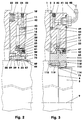
- Figur 1:
- perspektivische Ansicht einer Brems- und/oder Klemmvorrichtung mit einer auf einem Doppelradialspannflansch basierenden Wellen-Naben-Verbindung;
- Figur 2:
- Teilquerschnitt zu
Figur 1 - Figur 3:
- Teilquerschnitt einer Brems- und/oder Klemmvorrichtung mit gestufter Welle;
- Figur 4:
- Teilquerschnitt durch eine Wellen-Naben-Verbindung mit Verdrängerspannhülse, vergrößert;
- Figur 5:
- Teilquerschnitt durch eine Wellen-Naben-Verbindung mit Ringfederspannsatz, vergrößert;
- Figur 6:
- Teilquerschnitt zu
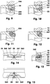
Figur 1Figur 2 - Figur 7:
- Teilquerschnitt durch einen Schraubring mit Radialsteg, vergrößert;
- Figur 8:
- Teilquerschnitt wie
Figur 7 - Figur 9:
- Teilquerschnitt durch einen Schraubring mit Stahlkugel, vergrößert unbetätigt;
- Figur 10:
- Teilquerschnitt wie
Figur 9 - Figur 11:
- Teilquerschnitt durch einen Schraubring mit Verdrängungskörper, vergrößert, unbetätigt;
- Figur 12:
- Teilquerschnitt wie
Figur 11 - Figur 13:
- Teilquerschnitt durch einen Schraubring mit Spreizschraube, vergrößert, unbetätigt;
- Figur 14:
- Stirnansicht
mit zu Figur 13 ; - Figur 15:
- Draufsicht mit Teilschnitt zu
Figur 14 .
- Figure 1:
- perspective view of a braking and / or clamping device with a shaft-hub connection based on a double radial clamping flange;
- Figure 2:
- Partial cross section
Figure 1 ; - Figure 3:
- Partial cross section of a braking and / or clamping device with a stepped shaft;
- Figure 4:
- Partial cross-section through a shaft-hub connection with displacement sleeve, enlarged;
- Figure 5:
- Partial cross section through a shaft-hub connection with a ring spring clamping set, enlarged;
- Figure 6:
- Partial cross section
Figure 1 , but offset from the cutFigure 2 ; - Figure 7:
- Partial cross section through a screw ring with radial web, enlarged;
- Figure 8:
- Partial cross section like
Figure 7 , but with bending plate and deformed radial web, enlarged; - Figure 9:
- Partial cross-section through a screw ring with a steel ball, enlarged not actuated;
- Figure 10:
- Partial cross section like
Figure 9 , but blocked, enlarged; - Figure 11:
- Partial cross-section through a screw ring with displacement body, enlarged, not actuated;
- Figure 12:
- Partial cross section like
Figure 11 , but blocked, enlarged; - Figure 13:
- Partial cross-section through a screw ring with expansion screw, enlarged, not actuated;
- Figure 14:
- Front view with too
Figure 13 ; - Figure 15:
- Top view with partial section too
Figure 14 ,
Der Druckraum (37) hat ein Volumen, das kleiner ist als 12,5 Prozent des Hüllvolumens der Betätigungsbaugruppe (10). Das Hüllvolumen der in den Figuren dargestellten Variante, entspricht einem gegebenen Volumen eines Rohrkörpers, der als Rohrlänge die Vorrichtungsbreite, als Außendurchmesser den äußeren Vorrichtungsdurchmesser und als Innendurchmesser den minimalen Innendurchmesser der Biegeplatte (15) hat.The pressure chamber (37) has a volume that is less than 12.5 percent of the envelope volume of the actuation assembly (10). The envelope volume of the variant shown in the figures corresponds to a given volume of a tubular body which has the device width as the pipe length, the outer device diameter as the outer diameter and the minimum inner diameter of the bending plate (15) as the inner diameter.
Die Betätigungsbaugruppe (10) weist ein ring- bzw. rohrförmiges Spaltgehäuse (11) auf, das den z.B. schmalspaltigen ringförmigen Druckraum (37) umschließt. Das Spaltgehäuse (11) ist im unverformten Zustand im Wesentlichen eine ebene Scheibe mit einem Innendurchmesser von z.B. ca. 280 mm und einem Außendurchmesser von z.B. 388 mm. Die maximale Dicke der Scheibe liegt z.B. bei 22 mm. Das Spaltgehäuse (11) ist aus einem Vergütungsstahl, z.B. 42CrMoS4, gefertigt. Es ist in drei Bereiche (13, 21, 22), vgl.
Das Spaltgehäuse (11) wird zur Herstellung des Spaltraumes (37) von seiner zentralen Bohrung (4) aus mittig zwischen den Stirnseiten ausgefräst. Dazu wird z.B. ein Scheibenfräser verwendet. Die ausgefräste, z.B. 38,7 mm tiefe Nut hat eine Spaltbreite von z.B. 4 mm. Der rinnenförmige Nutgrund hat hier einen Radius von 2 mm.To produce the gap space (37), the gap housing (11) is milled out from its central bore (4) centrally between the end faces. For this, e.g. used a side milling cutter. The milled, e.g. 38.7 mm deep groove has a gap width of e.g. 4 mm. The channel-shaped groove base has a radius of 2 mm here.
Die Anbauzone (13), in die der Spaltraum (37) nicht oder nur 1 bis 10 mm hineinragt, hat z.B. beidseitig eine zumindest bereichsweise plane Stirnfläche, über die das Spaltgehäuse (11) an einer Anbaufläche (3) des Grundkörpers (1) anlegbar ist, vgl. auch
Gemäß der
Die Zulaufgewindebohrung (41), vgl.
Die Verteilbohrungen (42, 43) haben hier einen Durchmesser von 3 mm. Das über den Hydraulikadapter (56) einströmende Hydrauliköl, z.B. ein Öl vom Typ HLP 46 nach DIN 51524, Teil 2, das bei 40° Celsius eine Viskosität von 46 ± 2 mm2/s aufweist, verteilt sich schnell im Druckraum (37).The distribution bores (42, 43) have a diameter of 3 mm here. The hydraulic oil flowing in via the hydraulic adapter (56), e.g. an HLP 46 type oil according to DIN 51524,
Nach
Die beiden an die Anbauzone (13) angeformten Biegeplatten (15, 16) stellen die elastische Biegezone (21) dar. Die beidseits des Spaltraumes (37) gelegenen, elastisch verformbaren Biegeplatten (15, 16) verjüngen sich - bezüglich ihrer Wandstärke - von außen her in Richtung der zentralen Mittellinie (9). Ihre Wandstärke verringert sich im Ausführungsbeispiel von z.B. 9 auf 6,2 und 7,5 mm, wobei die dickere Biegeplatte (15) den einstellbaren Schraubring (23) trägt. Die Formsteifigkeit der Biegeplatten (15, 16) nimmt somit in Richtung der Klemmzone (22) nahezu stetig ab. Die Übergänge zwischen den Zonen (13) und (21) sind beispielsweise mit großen Radien ausgerundet. Die Biegezone (21) ist gegenüber der Anbauzone (13) zurückgenommen, um die Verformung der Biegezone (21) nicht in die zwischen dem Grundkörper (1) und der Anbauzone (13) gelegene Einbaufuge einzutragen.The two bending plates (15, 16) formed on the attachment zone (13) represent the elastic bending zone (21). The elastically deformable bending plates (15, 16) located on both sides of the gap (37) taper from the outside with respect to their wall thickness towards the central center line (9). Their wall thickness decreases in the exemplary embodiment of e.g. 9 to 6.2 and 7.5 mm, the thicker bending plate (15) carrying the adjustable screw ring (23). The rigidity of the bending plates (15, 16) thus decreases almost continuously in the direction of the clamping zone (22). The transitions between zones (13) and (21) are rounded off, for example, with large radii. The bending zone (21) is withdrawn with respect to the attachment zone (13) so that the deformation of the bending zone (21) is not entered into the installation joint located between the base body (1) and the attachment zone (13).
Die Biegeplatten (15, 16) der Biegezone (21) gehen zur jeweiligen Wellenanbindungsbaugruppe (60) hin in die beiden Klemmzonen (22) über, die die umlaufenden Zangenbacken (23, 29) darstellen. Bei der nach den
Der Zangenbacken (29) hat innerhalb der Axialnut (17) eine plane Reibfläche (31). Die Reibfläche (31) hat im Ausführungsbeispiel einen mittleren Radius von 142,3 mm. In der Klemmzone (22) beträgt die maximale Breite der Reibfläche (31) z.B. 6 mm.The pliers jaw (29) has a flat friction surface (31) within the axial groove (17). In the exemplary embodiment, the friction surface (31) has an average radius of 142.3 mm. In the clamping zone (22) the maximum width of the friction surface (31) is, for example, 6 mm.
Die Biegeplatte (15) ist in Radialrichtung z.B. 6,2 mm kürzer als die Biegeplatte (16). Zudem endet sie in Richtung der Welle (5) in einem Innengewinde (18).The bending plate (15) is in the radial direction e.g. 6.2 mm shorter than the bending plate (16). In addition, it ends in the direction of the shaft (5) in an internal thread (18).
An der Biegeplatte (15) sitzt als Zangenbacken (23) ein Schraubring. Letzterer ist im Wesentlichen ein kurzer rohr- oder ringförmiger Körper, der zur Biegeplatte (15) hin ein Außengewinde (24) aufweist. Zudem ist am Schraubring (23) ein Kragring (25) angeformt, der im montierten Zustand des Zangenbackens (23) in die Axialnut (17) der Biegeplatte (15), z.B. mit allseitigem Spiel, hineinragt. Bei betätigter Klemmung ist zumindest ein axiales Spiel von mindestens 0,1 mm zwischen dem Grund der Axialnut (17) und dem freien stirnseitigen Ende des Kragringes (25) erforderlich. Werden sehr hohe Öldrücke benutzt, kann es notwendig sein, dass die Bohrungswandung des Kragringes (25) auf der inneren Nutwandung der Axialnut (17) aufliegt. Die innere Nutwandung ist die Nutwandung mit dem kleineren Durchmesser.A screw ring sits on the bending plate (15) as pliers jaws (23). The latter is essentially a short tubular or ring-shaped body which has an external thread (24) towards the bending plate (15). In addition, a collar ring (25) is formed on the screw ring (23), which in the assembled state of the pliers jaw (23) into the axial groove (17) of the bending plate (15), e.g. with all-round play, protrudes. When the clamping is actuated, at least an axial play of at least 0.1 mm between the base of the axial groove (17) and the free end of the cantilever ring (25) is required. If very high oil pressures are used, it may be necessary that the bore wall of the cantilever ring (25) rests on the inner groove wall of the axial groove (17). The inner groove wall is the groove wall with the smaller diameter.
Innerhalb des Kragringes (25) bildet die zum Spaltraum (37) hin orientierte Stirnfläche des Zangenbackens (23) eine plane Reibfläche (32). Die Abmessungen der Reibfläche (32) entsprechen denen der Reibfläche (31).Within the cantilever ring (25), the end face of the pliers jaw (23) oriented towards the gap space (37) forms a flat friction surface (32). The dimensions of the friction surface (32) correspond to those of the friction surface (31).
Der Schraubring bzw. Zangenbacken (23) hat eine radiale Ausdehnung von z.B. 7,5 mm bei einer axialen Länge von z.B. 12,9 mm. Der axial überstehende Kragring (25) ragt 5,4 mm über die Reibfläche (32) über. Die Wandstärke des am Schraubring (23) angeformten Kragringes (25) beträgt z.B. 2,2 mm. Die radiale Außenwandung des Kragringes (25) ist am freien Ende z.B. mit einer 15-Winkelgrad-Fase ausgestattet.The screw ring or pliers jaw (23) has a radial expansion of e.g. 7.5 mm with an axial length of e.g. 12.9 mm. The axially projecting cantilever ring (25) projects 5.4 mm over the friction surface (32). The wall thickness of the cantilever ring (25) formed on the screw ring (23) is e.g. 2.2 mm. The radial outer wall of the cantilever ring (25) is e.g. equipped with a 15 degree bevel.
Nach
Nach den
Im Schraubring (23) ist z.B. in jeder Gewindebohrung (235), gemäß der
Sobald der Schraubring (23) bei der Montage seine Einschraubsollposition im Innengewinde (18) erreicht hat, werden zur Verdrehsicherung des Schraubrings (23) gegenüber der Biegeplatte (15) die Gewindestifte (26) angezogen. Dabei pressen die Gewindestifte (26) den Radialsteg (231) über seine Abstützflanke (233) jeweils partiell unter einer beulenden elastischen und/oder plastischen Verformung in Richtung des Kragrings (25), vgl.
Nach einem Lösen aller Gewindestifte (26) lässt sich der Schraubring (23) gegenüber der Biegeplatte (15) wieder verdrehen, so dass während des Lebenszyklus der Brems- und/oder Klemmvorrichtung der Schraubring (23) mehrfach ein- oder verstellt werden kann.After loosening all the setscrews (26), the screw ring (23) can be rotated again relative to the bending plate (15), so that the screw ring (23) can be adjusted or adjusted several times during the life cycle of the braking and / or clamping device.
In einer Variante zur Ausführung nach den
Die
Nach
Die
Gemäß den
Bei einem Einschrauben des Gewindestifts (27) wird der Verdrängerkörper (256) so zu einem Körper (257) deformiert, dass dieser fast die gesamte Radialbohrung ausfüllt. Zugleich wird er (257) auch in die Gewinderillen des Innengewindes (18) gepresst, wodurch das für eine Verdrehsicherung erforderliche Haltemoment entsteht. Nach einem Lösen der Gewindestifte ist ein wiederholtes Verdrehen des Schraubrings (23) möglich, da der Verdrängerkörper (257) das Innengewinde unmerklich oder nicht deformiert.When the setscrew (27) is screwed in, the displacer (256) is deformed into a body (257) such that it fills almost the entire radial bore. At the same time, it (257) is also pressed into the thread grooves of the internal thread (18), which creates the holding torque required to prevent rotation. After loosening the setscrews, the screw ring (23) can be rotated repeatedly since the displacer (257) imperceptibly or not deforms the internal thread.
Abweichend vom dargestellten Ausführungsbeispiel, ist hier für den Gewindestift keine Kegelspitze erforderlich.In contrast to the exemplary embodiment shown, no conical tip is required for the threaded pin.
In den
Die Radialnut (262) wird mit einem in Richtung der Mittellinie (9) erfolgenden Vorschub gefräst. Hierbei hat das entsprechende Werkzeug, ein Scheibenfräser, einen Durchmesser von z.B. 40 mm. Die Eindringtiefe der Radialnut (262) ist erreicht, wenn sie den Kerndurchmesser der Gewindebohrung (265) vollständig schneidet. Der kürzeste Abstand zwischen der Mittellinie der Gewindebohrung (265) und der Hüllfläche des Außengewindes (24) des Schraubrings (23) beträgt hier z.B. 2,85 mm. Wie bei allen anderen Gewindebohrungen (235, 245) verläuft auch die Mittellinie dieser Gewindebohrung (265) parallel zur Mittellinie (9).The radial groove (262) is milled with a feed in the direction of the center line (9). The corresponding tool, a side milling cutter, has a diameter of, for example, 40 mm. The penetration depth of the radial groove (262) is reached when it completely intersects the core diameter of the threaded bore (265). The shortest distance between the center line of the threaded bore (265) and the envelope surface of the external thread (24) of the screw ring (23) is here, for example, 2.85 mm. As with all other threaded holes (235, 245), the center line of this threaded hole (265) runs parallel to the center line (9).
Der ebenfalls mit einem Scheibenfräser erzeugte Querschlitz (263) ist mittig zur Mittellinie der Gewindebohrung (265) und senkrecht zur Radialnut (262) orientiert. Der Querschlitz (263) wird hier mit einem Scheibenfräser bearbeitet, der einen Durchmesser von z.B. 30 mm aufweist. Auf diese Weise wird die Gewindebohrung (265) nur minimal geschwächt. Der Querschlitz (263) und die Radialnut (262) haben jeweils eine Breite von z.B. 0,4 mm.The transverse slot (263), also produced with a side milling cutter, is oriented in the center of the center line of the threaded bore (265) and perpendicular to the radial groove (262). The transverse slot (263) is machined here with a side milling cutter that has a diameter of e.g. 30 mm. In this way, the threaded bore (265) is only minimally weakened. The transverse slot (263) and the radial groove (262) each have a width of e.g. 0.4 mm.
Die Eindringtiefe des Querschlitzes (263), vgl.
In
Wird zum Herstellen der Verdrehsicherungen die einzelne Senkschraube (28) festgeschraubt, drückt der Schraubenkopf der Senkschraube (28) den Außengewindeanschnitt (267) der Klemmbrücke (261) geringfügig radial nach außen in das Innengewinde (18) der Biegeplatte (15). Dadurch verklemmt sich Außengewindeanschnitt (267) festhaltend im Innengewinde (18). Der kegelstumpfförmige Kopf der Senkschraube (28) wirkt wie ein Keil. Hierbei stellt sich die Mittellinie der Senkschraube (28) im Rahmen des Gewindespiels und der elastischen Verformbarkeit der Schraube kalkulierbar minimal schräg zur Mittellinie der Gewindebohrung (265).If the individual countersunk screw (28) is screwed tight to produce the anti-rotation device, the screw head of the countersunk screw (28) presses the external thread cut (267) of the clamping bridge (261) slightly radially outwards into the internal thread (18) of the bending plate (15). As a result, the external thread section (267) is jammed in the internal thread (18). The frustoconical head of the countersunk screw (28) acts like a wedge. Here, the center line of the countersunk screw (28) is within the scope of the thread play and the elastic deformability of the screw calculable minimally oblique to the center line of the threaded hole (265).
Nach dem Zusammenbau der Brems- und/oder Klemmvorrichtung und der Justierung des Schraubringes (23) liegen die Zangenbacken der Betätigungsbaugruppe (10), bei geklemmter Brems- und/oder Klemmvorrichtung, an einem Klemmflansch (62) des Kupplungsbereiches (61) einer Wellenanbindungsbaugruppe (60) an, vgl.
Anstelle der planen Reibflächen (31, 32), die zudem parallel zur Anbaufläche (3) orientiert sind, können die Reibflächen auch die Gestalt eines Kegelstumpfmantels oder eines Teilbereiches eines Torus haben.Instead of the flat friction surfaces (31, 32), which are also oriented parallel to the mounting surface (3), the friction surfaces can also have the shape of a truncated cone shell or a partial area of a torus.
Radial zur Mittellinie (9) hin wird der Spalt- bzw. Druckraum (37) durch eine Doppellippendichtung (50) abgeschlossen. Die aus z.B. einem Polyurethan mit einer Shore D-Härte von 57 gefertigte Doppellippendichtung (50) hat zwei radial nach außen orientierte Dichtlippen (51), die sich jeweils an den seitlichen Wandungen des Druckraumes (37) aufgrund der eigenen Elastizität und/oder zusätzlich durch den im Druckraum (37) anstehenden Innendruck anlegen. Die Bohrungswandung der Doppellippendichtung (50) liegt auf der glatten radialen Außenwandung des Kragringes (25) auf.The gap or pressure chamber (37) is closed radially towards the center line (9) by a double lip seal (50). The from e.g. A double-lip seal (50) made of polyurethane with a Shore D hardness of 57 has two radially outwardly oriented sealing lips (51), each of which is located on the side walls of the pressure chamber (37) due to its own elasticity and / or due to that in the pressure chamber (37) Apply the internal pressure. The bore wall of the double lip seal (50) lies on the smooth radial outer wall of the cantilever ring (25).
In den
Alternativ können die Reibflächen (31, 32) oder die Reibflächen (71, 72) eine Oberflächenstruktur aufweisen. Beispielsweise entsteht diese durch Sandstrahlen oder durch eine Diamant- oder Saphirbeschichtung. Derartige Beschichtungen weisen eine Schichtstärke von z.B. 0,038 mm auf. Die durchschnittliche Korngröße des Beschichtungsgrundmaterials liegt bei dieser Schichtstärke bei 30 µm.Alternatively, the friction surfaces (31, 32) or the friction surfaces (71, 72) can have a surface structure. For example, this is created by sandblasting or by a diamond or sapphire coating. Such coatings have a layer thickness of e.g. 0.038 mm. With this layer thickness, the average grain size of the coating base material is 30 µm.
Der Klemmflansch (62) geht in den Flanschkern (63) beidseitig über Entlastungskerben (65) über, vgl.
Der Flanschkern (63) nach
Der Klemmflansch (62) kann ggf. auch Quernuten aufweisen, die bis an den Flanschgrund (64) reichen. Auf diese Weise stehen anstatt eines vollständig umlaufenden Klemmflansches (62) mehrere oder viele Klemmstege vom Flanschkern (63) radial ab, um zwischen die Zangenbacken (23, 29) hineinzuragen. Die Klemmstege können dabei - zur Beeinflussung des Vorrichtungsgeräusches - mit konstanter oder unregelmäßiger Teilung vom Flanschkern (63) abstehen.The clamping flange (62) may also have transverse grooves that extend to the flange base (64). In this way, instead of a completely circumferential clamping flange (62), several or many clamping webs protrude radially from the flange core (63) in order to protrude between the jaws (23, 29). The clamping webs can protrude from the flange core (63) with a constant or irregular pitch in order to influence the device noise.
Die
Ggf. ist die Spannfläche (66), deren Innendurchmesser hier z.B. 260 mm beträgt, mit einer Diamant- oder Saphirbeschichtung ausgestattet, vgl. ggf. vorhandene Beschichtung der Reibflächen (31, 32) oder (71, 72). Anstelle der festhaftenden Beschichtung kann auch in die Montagefuge zwischen der Spannfläche (66) und der Wellenoberfläche eine Diamantpaste zum Verbessern der Haftung eingebracht werden. Alternativ kann die Spannfläche (66) und/oder die Wellenoberfläche im Sitzbereich des Flanschkerns (63) über eine Reibstruktur verfügen, die z.B. aufgelasert ist.Possibly. is the clamping surface (66), the inside diameter of which is e.g. Is 260 mm, equipped with a diamond or sapphire coating, cf. any existing coating of the friction surfaces (31, 32) or (71, 72). Instead of the firmly adhering coating, a diamond paste can also be introduced into the assembly joint between the clamping surface (66) and the shaft surface to improve the adhesion. Alternatively, the clamping surface (66) and / or the shaft surface in the seating area of the flange core (63) can have a friction structure, e.g. is lasered.
Werden nach dem Aufschieben der Vorrichtung auf die Welle (5) an dem vorgesehenen Einbauplatz die Schrauben (89) festgeschraubt, so werden die Spannflansche (81, 82) gegeneinander gezogen. Hierdurch legen sich aufgrund der gelenkartigen Nachgiebigkeit der Materialstege (86) des Flanschkerns (63) die Spannflansche (81, 82) über die Tragkanten (83), vgl.
Eine alternative Wellenanbindungsbaugruppe ist in
In die Stirnnut (102) ist als Verdrängerkörper ein ringförmiger Elastomerkörper (104) eingesetzt. Seine Breite überdeckt 55 bis 70% der Flanschkernbreite. Seine Wandstärke misst z.B. 5 mm. Zur Herstellung eines klemmenden Spannmechanismus (76) wird bei der Montage der Anbindungsbaugruppe (100) auf die Welle (5) in das Innengewinde (103) ein Gewindering (105), z.B. mittels eines Zapfenschlüssels, eingeschraubt. Der Elastomerkörper (104) wird so verdichtet, dass sich die Klemmhülsenwandung (101) verdrehfest an die Welle (5) anschmiegt.An annular elastomer body (104) is inserted into the end groove (102) as a displacement body. Its width covers 55 to 70% of the flange core width. Its wall thickness measures 5 mm, for example. to To produce a clamping clamping mechanism (76), a threaded ring (105) is screwed into the internal thread (103) when the connection module (100) is mounted on the shaft (5), for example by means of a spanner. The elastomer body (104) is compressed in such a way that the clamping sleeve wall (101) nestles against the shaft (5) so that it cannot rotate.
Der Elastomerkörper (104) ist beispielsweise aus dem Acrylnitril-Butadien-Kautschuk NBR hergestellt. Seine Härte in Shore A liegt zwischen 64 und 68.The elastomer body (104) is made, for example, from the acrylonitrile-butadiene rubber NBR. Shore A hardness is between 64 and 68.
Die
Auf diesen Kegelstumpfmänteln (91) sitzen beidseitig die Ringkegelspannelemente (93, 94) auf, um zusammen mit dem Flanschkern (63) eine als Spannmechanismus dienende Schrumpfscheibe zu bilden. Die Ringkegelspannelemente (93, 94) sind Ringe, deren zentrale Ausnehmungen (92) konisch passend zu den Kegelstumpfmänteln (91) gestaltet sind. Der Konuswinkel beträgt z.B. 5 Winkelgrade. Um Platz für die Zangenbacken (23, 29) der Betätigungsbaugruppe (10) zu lassen, sind die Ringkegelspannelemente (93, 94) jeweils an den Stirnseiten, die zum Klemmflansch (62) hin orientiert sind, mit z.B. an der engsten Stelle ca. 4,3 mm breiten und 10 mm tiefen Eindrehungen (97) versehen. Die Breite der Eindrehungen (97) vergrößert sich mit zunehmendem Radius stetig.The ring taper clamping elements (93, 94) sit on both sides of these truncated cones (91) in order to form a shrink disk serving as a clamping mechanism together with the flange core (63). The ring cone clamping elements (93, 94) are rings, the central recesses (92) of which are designed to match the truncated cone shells (91). The cone angle is, for example, 5 degrees. In order to leave space for the pliers jaws (23, 29) of the actuation assembly (10), the ring cone clamping elements (93, 94) are each on the end faces, which are oriented towards the clamping flange (62), for example at the narrowest point approx. 4 , 3 mm wide and 10 mm deep recesses (97). The width of the indentations (97) increases steadily with increasing radius.
Beide Ringkegelspannelemente (93, 94) tragen koaxiale Bohrungen (95, 96) für die Schrauben (99), mit denen die Ringkegelspannelemente (93, 94) unter axialer und radialer Verspannung gegen den dünnwandigen Flanschkern (63) gepresst werden. Das nach
Ausgeliefert wird diese Brems- und/oder Klemmvorrichtung in Kombination mit der gewählten Wellenanbindungsbaugruppe (80, 90, 100, 110). Dabei sitzt die jeweilige Wellenanbindungsbaugruppe (80, 90, 100, 110) koaxial in der Betätigungsbaugruppe (10). Für die Montage in der die Vorrichtung aufnehmenden Maschine wird die Wellenanbindungsbaugruppe (80, 90, 100, 110) auf die Welle (5) geschoben und dort direkt an der Anbaufläche (3) des Grundkörpers (1) anstehend - in der Regel lösbar - befestigt. Abschließend werden die Befestigungsschrauben (59) in die entsprechenden grundkörperseitigen Bohrungen eingesetzt und dort verschraubt.This brake and / or clamping device is delivered in combination with the selected shaft connection assembly (80, 90, 100, 110). The respective shaft connection assembly (80, 90, 100, 110) is located coaxially in the actuation assembly (10). For assembly in the machine receiving the device, the shaft connection assembly (80, 90, 100, 110) is pushed onto the shaft (5) and attached directly to the mounting surface (3) of the base body (1) - generally detachably - there , Finally, the fastening screws (59) are inserted into the corresponding holes on the base body and screwed there.
Steht im Druckraum (37) kein Hydraulikölbetriebsdruck an, so ist die Welle (5) gegenüber dem Grundkörper (1) festgeklemmt. Der Druckraum (37) weist keinen nennenswerten Öldruck auf, da der Ölzulauf über ein nicht dargestelltes Ventil in den Öltank entlastet ist. Die Biegeplatten (15, 16) liegen vorgespannt über ihre Zangenbacken (23, 29) am Klemmflansch (62) an, vgl. Figur 2. Die Vorspannung ergibt sich aus der Federrate der vorgebeulten Biegeplatten (15, 16). Die Höhe der Federrate ist eine Funktion der ringscheibenseitigen Werkstoffauswahl und der Geometrie der Biegezone (21). Das erzeugte Brems- bzw. Haltemoment liegt bei den Ausführungsbeispielen bei 3000 ± 200 Nm.If there is no hydraulic oil operating pressure in the pressure chamber (37), the shaft (5) is clamped in relation to the base body (1). The pressure chamber (37) has no appreciable oil pressure, since the oil supply to the oil tank is relieved via a valve (not shown). The bending plates (15, 16) are biased against their clamping jaws (23, 29) on the clamping flange (62), cf. figure 2. The preload results from the spring rate of the bulged bending plates (15, 16). The height of the spring rate is a function of the material selection on the ring disc side and the geometry of the bending zone (21). The braking or holding torque generated is 3000 ± 200 Nm in the exemplary embodiments.
Die Biegeplatten (15, 16) befänden sich nur dann im vollständig entspannten Zustand, wenn kein Klemmflansch (62) zwischen den Zangenbacken (23, 29) läge. Dann wäre im Ausführungsbeispiel der Druckraum (37) ein Spaltraum mit konstanter Spaltbreite.The bending plates (15, 16) would only be in the fully relaxed state if there was no clamping flange (62) between the jaws (23, 29). Then, in the exemplary embodiment, the pressure space (37) would be a gap space with a constant gap width.
Um die Brems- und/oder Klemmvorrichtung zu lösen, wird z.B. über den Hydraulikadapter (56), vgl.
Kombinationen der in den Figuren gezeigten Ausführungsbeispiele und deren Varianten sind denkbar.Combinations of the exemplary embodiments shown in the figures and their variants are conceivable.
- 11
- Grundkörperbody
- 22
- Zentrierung, AußenzentrierungCentering, external centering
- 33
- Anbaufläche von (1)Acreage of (1)
- 44
- Bohrung, zentral von (10)Central bore from (10)
- 55
- Wellewave
- 66
- Wellenbundshaft collar
- 77
- Mittenebenemidplane
- 88th
- fiktive Achse, vertikalfictional axis, vertical
- 99
- Mittellinie der Vorrichtung, zentralCenter line of the device, central
- 1010
- Betätigungsbaugruppeactuating assembly
- 1111
- Spaltgehäuse, bereichsweise beulbarSplit housing, can be dented in some areas
- 1212
- Vorderseite, StirnseiteFront, front
- 1313
- Anbauzonegrowing zone
- 1414
- Außenwandung, Stirnwandung, StirnseiteOuter wall, end wall, end face
- 1515
- Biegeplatte, außen, kleinBending plate, outside, small
- 1616
- Biegeplatte, innen, großBending plate, inside, large
- 1717
- Axialnut in (15)Axial groove in (15)
- 1818
- Innengewinde, FeingewindeInternal thread, fine thread
- 2121
- Biegezone, beulbar, elastischBending zone, dentable, elastic
- 2222
- Klemmzonenclamping zones
- 2323
- Zangenbacke, angeschraubt, Verstellring, SchraubringPliers jaw, screwed on, adjusting ring, screw ring
- 2424
- Außengewinde, FeingewindeMale thread, fine thread
- 2525
- KragringKragring
- 2626
- Gewindestift mit KegelkuppeGrub screw with cone tip
- 2727
- Gewindestift mit SpitzeGrub screw with tip
- 2828
- Senkschraube, SpreizschraubeCountersunk screw, expansion screw
- 2929
- Zangenbacken, angeformtPliers jaws, molded
- 31, 3231, 32
- Reibflächenfriction surfaces
- 3333
- Flächennormalen von (31, 32)Surface normals of (31, 32)
- 3434
- Stirnfläche von (23)Face of (23)
- 3737
- Druckraum; Spaltraum; NutPressure chamber; Gap; groove
- 4141
- ZulaufgewindebohrungenTapered threaded holes
- 4242
- Verteilbohrung, radialDistribution bore, radial
- 4343
- Verteilbohrung, axialDistribution bore, axial
- 4545
- Bohrungen mit Senkungen, Durchgangsbohrungen, BefestigungsbohrungenCounterbored holes, through holes, mounting holes
- 4747
- Pfeile, BewegungsrichtungArrows, direction of movement
- 4848
- HydraulikölzulaufHydraulic oil supply
- 4949
- Schneidringcutting ring
- 5050
- Doppellippendichtung, DichtringDouble lip seal, sealing ring
- 5151
- Dichtlippensealing lips
- 5252
- VerschlussstopfengewindebohrungClosure plug thread hole
- 5353
- Klemmbüchseclamping bush
- 5454
- StauchkugelStauch ball
- 5555
- Verschlussstopfensealing plug
- 5656
- Hydraulikadapterhydraulic adapters
- 5959
- Befestigungsschraubenmounting screws
- 6060
- WellenanbindungsbaugruppeShaft connection assembly
- 6161
- Kupplungsbereichcoupling region
- 6262
- Klemmflansch, zentralClamping flange, central
- 6363
- FlanschkernFlanschkern
- 6464
- FlanschgrundFlanschgrund
- 6565
- Entlastungskerbenrelief notches
- 6666
- Bohrung, zentral; Spannfläche von (60)Central bore; Clamping surface of (60)
- 71, 7271, 72
- Reibflächenfriction surfaces
- 7373
- Flächennormalen von (71, 72)Area normals from (71, 72)
- 7575
- WellenanbindungsbereichShaft connection area
- 7676
- Spannmechanismustensioning mechanism
- 8080
- Wellenanbindungsbaugruppe mit DoppelradialspannflanschShaft connection assembly with double radial clamping flange
- 81, 8281, 82
- Spannflansch, radial; links, rechtsClamping flange, radial; Left Right
- 8383
- Tragkantensupport edges
- 8585
- Nutgroove
- 8686
- Materialstegmaterial web
- 8787
- Bohrung mit KegelsenkungHole with countersink
- 8888
- Gewindebohrungthreaded hole
- 8989
- Schraube, ZylinderkopfschraubeBolt, cylinder head bolt
- 9090
- Wellenanbindungsbaugruppe mit SchrumpfscheibenverbindungShaft connection assembly with shrink disc connection
- 9191
- Kegelstumpfmäntel, Außenwandungen, radial; KonenTruncated cone shells, outer walls, radial; Konen
- 9292
- Ausnehmungen, zentral in (93, 94)Recesses, central in (93, 94)
- 93, 9493, 94
- RingkegelspannelementeRing Cone clamping elements
- 9595
- Bohrung mit SenkungCountersink hole
- 9696
- Gewindebohrungthreaded hole
- 9797
- Eindrehungrecess
- 9898
- Bohrung in (62)Hole in (62)
- 9999
- Schraubenscrew
- 100100
- Wellenanbindungsbaugruppe mit VerdrängerspannhülseShaft connection assembly with displacement sleeve
- 101101
- KlemmhülsenwandungKlemmhülsenwandung
- 102102
- Stirnnut, Ausnehmung für (104) und (105)Face groove, recess for (104) and (105)
- 103103
- Innengewinde, FeingewindeInternal thread, fine thread
- 104104
- Elastomerkörper, Gummikörper, VerdrängerkörperElastomer body, rubber body, displacement body
- 105105
- Gewinderingthreaded ring
- 110110
- Wellenanbindungsbaugruppe mit AxialmontageflanschShaft connection assembly with axial mounting flange
- 111111
- AxialmontageflanschAxialmontageflansch
- 112112
- Stufenbohrungstepped bore
- 113113
- Sitzfläche, radialSeat, radial
- 114114
- Bundfläche, planCollar surface, flat
- 115115
- Bohrungen für (119)Bores for (119)
- 119119
- Schraubenscrew
- 231231
- Radialsteg, umlaufend oder partiellRadial web, all-round or partial
- 232232
- Radialnut, außen, gewindestiftnaheRadial groove, outside, near the setscrew
- 233233
- AbstützflankeAbstützflanke
- 234234
- Radialnut, innenRadial groove, inside
- 235235
- Gewindebohrungthreaded hole
- 237237
- Außengewinde des Radialstegs, AußengewindeabschnittExternal thread of the radial web, external thread section
- 241241
- Radialbohrungradial bore
- 244244
- Kegelspitzeapex
- 245245
- Gewindebohrungthreaded hole
- 246246
- Kugel, formsteif; Stahlkugel, Umlenkkörper, EinstauchkörperBall, rigid; Steel ball, deflection body, immersion body
- 256256
- Verdrängungskörper, Kugel, verformbar;Displacement body, ball, deformable;
- 257257
- Verdrängungskörper, verformtDisplacer, deformed
- 261261
- Klemmbrücketerminal link
- 262262
- Radialnut, partiellRadial groove, partial
- 263263
- Querschlitztransverse slot
- 265265
- Gewindebohrungthreaded hole
- 266266
- Kegelsenkungcountersink
- 267267
- Außengewinde der Klemmbrücke, AußengewindeabschnittExternal thread of the clamping bridge, external thread section
Claims (8)
- Braking and/or clamping device for a shaft (5) guided relative to a base body (1) comprising an actuating assembly (10) and a shaft connection assembly (60),- wherein the actuating assembly (10) has a split housing (11) which has a mounting zone (13) and a bending zone (21) which is elastically deformable in some regions and has two bending plates (15, 16) separated by a gap space (37),- wherein, in two opposite clamping zones (22), the bending plates (15, 16) each have clamping jaws (23, 29) with friction surfaces (31, 32), whose surface normals (33) are directed inwards,- wherein a sealed pressure chamber (37), which is fillable with a pressure medium for elastically pushing the friction surfaces (31, 32) apart, lies between the two bending plates (15, 16),- wherein the shaft connection assembly (60) has a coupling region (61) which has two friction surfaces (71, 72) spaced apart from one another and whose surface normals (73) are directed outward,- wherein the shaft connection assembly (60) has a shaft connection region (75),- wherein the shaft connection region (75) is arranged either directly or indirectly on the coupling region (61) via a clamping mechanism (76),- wherein, when the pressure space (37) is released, the friction surfaces (31, 32) of the actuating assembly (10) can be applied to the friction surfaces (71, 72) of the shaft connection assembly (60) to provide the clamping and/or braking force, characterized in that at least one clamping jaw is a fixable adjusting ring (23) - having an axially projecting bearing ring (25) - adjustably arranged on the respective bending plate (15) in the clamping direction of the device.
- Braking and/or clamping device according to claim 1, characterized in that the at least one adjusting ring (23) is a screw ring, which can be screwed on the respective bending plate (15).
- Braking and/or clamping device according to claim 2, characterized in that a fine-pitch thread is arranged in the mounting and adjusting joint between the bending plate (15) and the screw ring (23), wherein the bending plate (15) has the internal thread (18) and the screw ring (23) has the external thread (24).
- Braking and/or clamping device according to claim 3, characterized in that the external thread (24) of the screw ring (23) has an external thread section (237, 267) which - for securing the screw ring (23) against rotating within the bending plate (15) -can be clamped, with respect to the internal thread (18) of the bending plate (15), parallel or perpendicular to the screw-in direction of the screw ring (23).
- Braking and/or clamping device according to claim 3, characterized in that a circumferential radial web (231) - likewise equipped with an external thread (237) - is separated in or on the external thread (24) of the screw ring (23), the threads of said radial web engage, like the external thread (24), into the internal thread (18), wherein the radial web (231) is arranged to be displaceable or deformable with respect to the screw ring (23).
- Braking and/or clamping device according to claim 1, characterized in that the at least one adjusting ring (23) can be fixed in a spatially positive-locking manner with respect to the respective bending plate (15) by means of at least three compression bodies (246).
- Braking and/or clamping device according to claim 6, characterized in that the compression body (246) is a dimensionally stable ball, which can be clamped in the radial direction against the bending plate (15) by means of a pointed threaded pin (27) according to the sliding wedge principle.
- Braking and/or clamping device according to claim 1, characterized in that the at least one adjusting ring (23) can be fixed in a spatially positive-locking manner with respect to the respective bending plate (15) by means of at least three displacement bodies (256).
Applications Claiming Priority (1)
| Application Number | Priority Date | Filing Date | Title |
|---|---|---|---|
| DE102017004403.1A DE102017004403B4 (en) | 2017-05-09 | 2017-05-09 | Brake and / or clamping device with an actuating and a shaft connection assembly III |
Publications (2)
| Publication Number | Publication Date |
|---|---|
| EP3403758A1 EP3403758A1 (en) | 2018-11-21 |
| EP3403758B1 true EP3403758B1 (en) | 2020-01-29 |
Family
ID=62148085
Family Applications (1)
| Application Number | Title | Priority Date | Filing Date |
|---|---|---|---|
| EP18000436.8A Active EP3403758B1 (en) | 2017-05-09 | 2018-05-08 | Adjustable attachment adapter |
Country Status (2)
| Country | Link |
|---|---|
| EP (1) | EP3403758B1 (en) |
| DE (1) | DE102017004403B4 (en) |
Families Citing this family (3)
| Publication number | Priority date | Publication date | Assignee | Title |
|---|---|---|---|---|
| DE102018009513B4 (en) * | 2018-12-06 | 2020-09-10 | Günther Zimmer | Braking and / or clamping device with an actuating assembly and a shaft connection assembly IV |
| DE102019004953B4 (en) * | 2019-07-17 | 2021-10-28 | Günther Zimmer | Braking and / or clamping device with one-piece gap housing and sensor module |
| DE102020003061B4 (en) | 2020-05-23 | 2021-12-30 | Günther Zimmer | Braking and / or clamping device with an actuation assembly and a shaft connection assembly V |
Family Cites Families (10)
| Publication number | Priority date | Publication date | Assignee | Title |
|---|---|---|---|---|
| DE2106009A1 (en) | 1971-02-09 | 1972-08-24 | Brunner G | |
| JPS5712889Y2 (en) * | 1979-12-29 | 1982-03-15 | ||
| DE3046156C2 (en) | 1980-12-06 | 1983-01-13 | Kuka Schweissanlagen + Roboter Gmbh, 8900 Augsburg | Actuating device for disc brakes |
| US5386769A (en) * | 1989-10-03 | 1995-02-07 | Rinne; Erkki | Adjustable press roller using silicone elastomer as pressure medium |
| US6629584B1 (en) | 1999-11-11 | 2003-10-07 | Innotech Engineering Gmbh | Clamping and/or braking device |
| DE102008020518B4 (en) | 2008-04-23 | 2012-05-03 | Günther Zimmer | Brake and / or clamping device for shafts |
| US8534429B2 (en) * | 2011-08-31 | 2013-09-17 | Xerox Corporation | Piezo-actuated braking system and method for a stepper motor |
| CN102774769A (en) * | 2012-07-19 | 2012-11-14 | 石家庄五龙制动器股份有限公司 | Binary synchronization electromagnetic block brake of gantry |
| DE102016005549B3 (en) | 2016-05-09 | 2017-08-10 | Günther Zimmer | Brake and / or clamping device with an actuating and a shaft connection assembly |
| DE102016009581B3 (en) | 2016-08-09 | 2017-08-03 | Günther Zimmer | Brake and / or clamping device with an actuating and a shaft connection assembly II |
-
2017
- 2017-05-09 DE DE102017004403.1A patent/DE102017004403B4/en active Active
-
2018
- 2018-05-08 EP EP18000436.8A patent/EP3403758B1/en active Active
Non-Patent Citations (1)
| Title |
|---|
| None * |
Also Published As
| Publication number | Publication date |
|---|---|
| DE102017004403A1 (en) | 2018-11-15 |
| DE102017004403B4 (en) | 2018-11-22 |
| EP3403758A1 (en) | 2018-11-21 |
Similar Documents
| Publication | Publication Date | Title |
|---|---|---|
| EP3496899B1 (en) | Braking and/or clamping device having an actuation assembly and a shaft-coupling assembly ii | |
| DE60021730T2 (en) | High-strength blind bolt over an extended gripping area of uniformly high clamping force | |
| EP3403758B1 (en) | Adjustable attachment adapter | |
| DE2944648A1 (en) | DEVICE FOR ATTACHING AN AXLE OR THE LIKE IN ONE HUB AND APPLICATION | |
| EP3455516B1 (en) | Braking and/or clamping device having an actuation and a shaft-coupling assembly | |
| DE2061565C3 (en) | Chuck for tools with cylindrical shank | |
| EP2832478B1 (en) | Connection system and intermediate bush and kit with an intermediate bush and a detent bolt for use in such a connection system | |
| EP0753368B1 (en) | Clamping device for precise relative fixation of two pieces | |
| EP3515659B1 (en) | Clamping device series connection | |
| EP2112396A1 (en) | Braking and/or clamping device for shafts and guide rails | |
| EP1714045B1 (en) | Shrink disc unit and tool for assembly thereof | |
| EP2112395B1 (en) | Braking and/or clamping device for shafts | |
| EP2896864A1 (en) | Connection system | |
| WO2017054927A2 (en) | Tensioning unit for rolling bearings on axles and shafts | |
| DE102018009513B4 (en) | Braking and / or clamping device with an actuating assembly and a shaft connection assembly IV | |
| DE102020003061B4 (en) | Braking and / or clamping device with an actuation assembly and a shaft connection assembly V | |
| DE102006019350B3 (en) | Braking and clamping device for shaft, has clamping ring arranged rotationally in device housing, and clamping ring has flanging area, middle area and clamping area | |
| DE102006048341A1 (en) | Loose-locking arrangement for a screw-in element | |
| DE4025773C1 (en) | Clamping irregular shaped workpieces - involves plates made of hard flexible material | |
| EP4063064A1 (en) | Retrofit group with tensioning system | |
| DE10361622C5 (en) | cutting tool | |
| DE102019207320A1 (en) | Sealing plug for a hollow shaft | |
| DE202005006469U1 (en) | Hydraulic cylinder piston | |
| DE19960382A1 (en) | Automotive ball and socket joint bolt has air bleed thread inclined to main anchorage thread reducing manufacturing tool wear costs |
Legal Events
| Date | Code | Title | Description |
|---|---|---|---|
| PUAI | Public reference made under article 153(3) epc to a published international application that has entered the european phase |
Free format text: ORIGINAL CODE: 0009012 |
|
| STAA | Information on the status of an ep patent application or granted ep patent |
Free format text: STATUS: THE APPLICATION HAS BEEN PUBLISHED |
|
| AK | Designated contracting states |
Kind code of ref document: A1 Designated state(s): AL AT BE BG CH CY CZ DE DK EE ES FI FR GB GR HR HU IE IS IT LI LT LU LV MC MK MT NL NO PL PT RO RS SE SI SK SM TR |
|
| AX | Request for extension of the european patent |
Extension state: BA ME |
|
| STAA | Information on the status of an ep patent application or granted ep patent |
Free format text: STATUS: REQUEST FOR EXAMINATION WAS MADE |
|
| 17P | Request for examination filed |
Effective date: 20190516 |
|
| RBV | Designated contracting states (corrected) |
Designated state(s): AL AT BE BG CH CY CZ DE DK EE ES FI FR GB GR HR HU IE IS IT LI LT LU LV MC MK MT NL NO PL PT RO RS SE SI SK SM TR |
|
| GRAP | Despatch of communication of intention to grant a patent |
Free format text: ORIGINAL CODE: EPIDOSNIGR1 |
|
| STAA | Information on the status of an ep patent application or granted ep patent |
Free format text: STATUS: GRANT OF PATENT IS INTENDED |
|
| INTG | Intention to grant announced |
Effective date: 20190812 |
|
| GRAS | Grant fee paid |
Free format text: ORIGINAL CODE: EPIDOSNIGR3 |
|
| GRAA | (expected) grant |
Free format text: ORIGINAL CODE: 0009210 |
|
| STAA | Information on the status of an ep patent application or granted ep patent |
Free format text: STATUS: THE PATENT HAS BEEN GRANTED |
|
| AK | Designated contracting states |
Kind code of ref document: B1 Designated state(s): AL AT BE BG CH CY CZ DE DK EE ES FI FR GB GR HR HU IE IS IT LI LT LU LV MC MK MT NL NO PL PT RO RS SE SI SK SM TR |
|
| REG | Reference to a national code |
Ref country code: GB Ref legal event code: FG4D Free format text: NOT ENGLISH |
|
| REG | Reference to a national code |
Ref country code: CH Ref legal event code: EP |
|
| REG | Reference to a national code |
Ref country code: AT Ref legal event code: REF Ref document number: 1228135 Country of ref document: AT Kind code of ref document: T Effective date: 20200215 |
|
| REG | Reference to a national code |
Ref country code: IE Ref legal event code: FG4D Free format text: LANGUAGE OF EP DOCUMENT: GERMAN |
|
| REG | Reference to a national code |
Ref country code: DE Ref legal event code: R096 Ref document number: 502018000672 Country of ref document: DE |
|
| REG | Reference to a national code |
Ref country code: NL Ref legal event code: MP Effective date: 20200129 |
|
| PG25 | Lapsed in a contracting state [announced via postgrant information from national office to epo] |
Ref country code: RS Free format text: LAPSE BECAUSE OF FAILURE TO SUBMIT A TRANSLATION OF THE DESCRIPTION OR TO PAY THE FEE WITHIN THE PRESCRIBED TIME-LIMIT Effective date: 20200129 Ref country code: NO Free format text: LAPSE BECAUSE OF FAILURE TO SUBMIT A TRANSLATION OF THE DESCRIPTION OR TO PAY THE FEE WITHIN THE PRESCRIBED TIME-LIMIT Effective date: 20200429 Ref country code: FI Free format text: LAPSE BECAUSE OF FAILURE TO SUBMIT A TRANSLATION OF THE DESCRIPTION OR TO PAY THE FEE WITHIN THE PRESCRIBED TIME-LIMIT Effective date: 20200129 Ref country code: PT Free format text: LAPSE BECAUSE OF FAILURE TO SUBMIT A TRANSLATION OF THE DESCRIPTION OR TO PAY THE FEE WITHIN THE PRESCRIBED TIME-LIMIT Effective date: 20200621 |
|
| REG | Reference to a national code |
Ref country code: LT Ref legal event code: MG4D |
|
| PG25 | Lapsed in a contracting state [announced via postgrant information from national office to epo] |
Ref country code: LV Free format text: LAPSE BECAUSE OF FAILURE TO SUBMIT A TRANSLATION OF THE DESCRIPTION OR TO PAY THE FEE WITHIN THE PRESCRIBED TIME-LIMIT Effective date: 20200129 Ref country code: SE Free format text: LAPSE BECAUSE OF FAILURE TO SUBMIT A TRANSLATION OF THE DESCRIPTION OR TO PAY THE FEE WITHIN THE PRESCRIBED TIME-LIMIT Effective date: 20200129 Ref country code: HR Free format text: LAPSE BECAUSE OF FAILURE TO SUBMIT A TRANSLATION OF THE DESCRIPTION OR TO PAY THE FEE WITHIN THE PRESCRIBED TIME-LIMIT Effective date: 20200129 Ref country code: GR Free format text: LAPSE BECAUSE OF FAILURE TO SUBMIT A TRANSLATION OF THE DESCRIPTION OR TO PAY THE FEE WITHIN THE PRESCRIBED TIME-LIMIT Effective date: 20200430 Ref country code: BG Free format text: LAPSE BECAUSE OF FAILURE TO SUBMIT A TRANSLATION OF THE DESCRIPTION OR TO PAY THE FEE WITHIN THE PRESCRIBED TIME-LIMIT Effective date: 20200429 Ref country code: IS Free format text: LAPSE BECAUSE OF FAILURE TO SUBMIT A TRANSLATION OF THE DESCRIPTION OR TO PAY THE FEE WITHIN THE PRESCRIBED TIME-LIMIT Effective date: 20200529 |
|
| PG25 | Lapsed in a contracting state [announced via postgrant information from national office to epo] |
Ref country code: NL Free format text: LAPSE BECAUSE OF FAILURE TO SUBMIT A TRANSLATION OF THE DESCRIPTION OR TO PAY THE FEE WITHIN THE PRESCRIBED TIME-LIMIT Effective date: 20200129 |
|
| PG25 | Lapsed in a contracting state [announced via postgrant information from national office to epo] |
Ref country code: SK Free format text: LAPSE BECAUSE OF FAILURE TO SUBMIT A TRANSLATION OF THE DESCRIPTION OR TO PAY THE FEE WITHIN THE PRESCRIBED TIME-LIMIT Effective date: 20200129 Ref country code: RO Free format text: LAPSE BECAUSE OF FAILURE TO SUBMIT A TRANSLATION OF THE DESCRIPTION OR TO PAY THE FEE WITHIN THE PRESCRIBED TIME-LIMIT Effective date: 20200129 Ref country code: DK Free format text: LAPSE BECAUSE OF FAILURE TO SUBMIT A TRANSLATION OF THE DESCRIPTION OR TO PAY THE FEE WITHIN THE PRESCRIBED TIME-LIMIT Effective date: 20200129 Ref country code: ES Free format text: LAPSE BECAUSE OF FAILURE TO SUBMIT A TRANSLATION OF THE DESCRIPTION OR TO PAY THE FEE WITHIN THE PRESCRIBED TIME-LIMIT Effective date: 20200129 Ref country code: LT Free format text: LAPSE BECAUSE OF FAILURE TO SUBMIT A TRANSLATION OF THE DESCRIPTION OR TO PAY THE FEE WITHIN THE PRESCRIBED TIME-LIMIT Effective date: 20200129 Ref country code: EE Free format text: LAPSE BECAUSE OF FAILURE TO SUBMIT A TRANSLATION OF THE DESCRIPTION OR TO PAY THE FEE WITHIN THE PRESCRIBED TIME-LIMIT Effective date: 20200129 Ref country code: SM Free format text: LAPSE BECAUSE OF FAILURE TO SUBMIT A TRANSLATION OF THE DESCRIPTION OR TO PAY THE FEE WITHIN THE PRESCRIBED TIME-LIMIT Effective date: 20200129 Ref country code: CZ Free format text: LAPSE BECAUSE OF FAILURE TO SUBMIT A TRANSLATION OF THE DESCRIPTION OR TO PAY THE FEE WITHIN THE PRESCRIBED TIME-LIMIT Effective date: 20200129 |
|
| REG | Reference to a national code |
Ref country code: DE Ref legal event code: R097 Ref document number: 502018000672 Country of ref document: DE |
|
| REG | Reference to a national code |
Ref country code: DE Ref legal event code: R119 Ref document number: 502018000672 Country of ref document: DE |
|
| PLBE | No opposition filed within time limit |
Free format text: ORIGINAL CODE: 0009261 |
|
| STAA | Information on the status of an ep patent application or granted ep patent |
Free format text: STATUS: NO OPPOSITION FILED WITHIN TIME LIMIT |
|
| 26N | No opposition filed |
Effective date: 20201030 |
|
| PG25 | Lapsed in a contracting state [announced via postgrant information from national office to epo] |
Ref country code: MC Free format text: LAPSE BECAUSE OF FAILURE TO SUBMIT A TRANSLATION OF THE DESCRIPTION OR TO PAY THE FEE WITHIN THE PRESCRIBED TIME-LIMIT Effective date: 20200129 |
|
| PG25 | Lapsed in a contracting state [announced via postgrant information from national office to epo] |
Ref country code: SI Free format text: LAPSE BECAUSE OF FAILURE TO SUBMIT A TRANSLATION OF THE DESCRIPTION OR TO PAY THE FEE WITHIN THE PRESCRIBED TIME-LIMIT Effective date: 20200129 Ref country code: PL Free format text: LAPSE BECAUSE OF FAILURE TO SUBMIT A TRANSLATION OF THE DESCRIPTION OR TO PAY THE FEE WITHIN THE PRESCRIBED TIME-LIMIT Effective date: 20200129 |
|
| REG | Reference to a national code |
Ref country code: BE Ref legal event code: MM Effective date: 20200531 |
|
| PG25 | Lapsed in a contracting state [announced via postgrant information from national office to epo] |
Ref country code: LU Free format text: LAPSE BECAUSE OF NON-PAYMENT OF DUE FEES Effective date: 20200508 |
|
| PG25 | Lapsed in a contracting state [announced via postgrant information from national office to epo] |
Ref country code: IE Free format text: LAPSE BECAUSE OF NON-PAYMENT OF DUE FEES Effective date: 20200508 |
|
| PG25 | Lapsed in a contracting state [announced via postgrant information from national office to epo] |
Ref country code: DE Free format text: LAPSE BECAUSE OF NON-PAYMENT OF DUE FEES Effective date: 20201201 Ref country code: BE Free format text: LAPSE BECAUSE OF NON-PAYMENT OF DUE FEES Effective date: 20200531 |
|
| REG | Reference to a national code |
Ref country code: CH Ref legal event code: PL |
|
| PG25 | Lapsed in a contracting state [announced via postgrant information from national office to epo] |
Ref country code: LI Free format text: LAPSE BECAUSE OF NON-PAYMENT OF DUE FEES Effective date: 20210531 Ref country code: CH Free format text: LAPSE BECAUSE OF NON-PAYMENT OF DUE FEES Effective date: 20210531 |
|
| PG25 | Lapsed in a contracting state [announced via postgrant information from national office to epo] |
Ref country code: TR Free format text: LAPSE BECAUSE OF FAILURE TO SUBMIT A TRANSLATION OF THE DESCRIPTION OR TO PAY THE FEE WITHIN THE PRESCRIBED TIME-LIMIT Effective date: 20200129 Ref country code: MT Free format text: LAPSE BECAUSE OF FAILURE TO SUBMIT A TRANSLATION OF THE DESCRIPTION OR TO PAY THE FEE WITHIN THE PRESCRIBED TIME-LIMIT Effective date: 20200129 Ref country code: CY Free format text: LAPSE BECAUSE OF FAILURE TO SUBMIT A TRANSLATION OF THE DESCRIPTION OR TO PAY THE FEE WITHIN THE PRESCRIBED TIME-LIMIT Effective date: 20200129 |
|
| PG25 | Lapsed in a contracting state [announced via postgrant information from national office to epo] |
Ref country code: MK Free format text: LAPSE BECAUSE OF FAILURE TO SUBMIT A TRANSLATION OF THE DESCRIPTION OR TO PAY THE FEE WITHIN THE PRESCRIBED TIME-LIMIT Effective date: 20200129 Ref country code: AL Free format text: LAPSE BECAUSE OF FAILURE TO SUBMIT A TRANSLATION OF THE DESCRIPTION OR TO PAY THE FEE WITHIN THE PRESCRIBED TIME-LIMIT Effective date: 20200129 |
|
| PGFP | Annual fee paid to national office [announced via postgrant information from national office to epo] |
Ref country code: IT Payment date: 20230529 Year of fee payment: 6 Ref country code: FR Payment date: 20230523 Year of fee payment: 6 |
|
| PGFP | Annual fee paid to national office [announced via postgrant information from national office to epo] |
Ref country code: GB Payment date: 20230526 Year of fee payment: 6 |