HINTERGRUND DER ERFINDUNGBACKGROUND OF THE INVENTION
Die vorliegende Erfindung betrifft einen Wärmetauscher, der beispielsweise als ein Kondensator einer an einem Automobil angebrachten Autoklimaanlage verwendet wird.The present invention relates to a heat exchanger used, for example, as a condenser of a car-mounted automobile air conditioner.
Hierin umfasst der Begriff „Kondensator” nicht nur einen gewöhnlichen Kondensator, sondern auch einen Unterkühlungskondensator mit einem Kondensationsabschnitt und einem Unterkühlungsabschnitt.Herein, the term "condenser" includes not only a usual condenser but also a subcooling condenser having a condensing section and a subcooling section.
Hierin und in den angehängten Ansprüchen wird die obere Seite, untere Seite, linkshändige Seite und rechtshändige Seite von 1 und 3 als „obere”, „untere”, „linke” beziehungsweise „rechte” bezeichnet.Herein and in the appended claims, the upper side, lower side, left-hand side and right-hand side of 1 and 3 referred to as "upper,""lower,""left," and "right," respectively.
Zum Beispiel wurde verlangt, dass ein Kondensator einer Autoklimaanlage bei der Kühlmittel-Kondensationseffizienz und Kühlmittel-Unterkühlungseffizienz weiter verbessert wird. Um eine derartige Anforderung zu erfüllen, hat der Anmelder der vorliegenden Erfindung einen verbesserten Kondensator vorgeschlagen (siehe Schrift der WO 2010/047320 ). Der vorgeschlagene Kondensator weist einen Kondensationsabschnitt und einen Unterkühlungsabschnitt auf, die derart vorgesehen sind, dass sich der Kondensationsabschnitt an der oberen Seite befindet. Der Kondensator umfasst eine Vielzahl von Wärmeaustauschrohren, gewellten Lamellen und Sammelbehältern. Die Wärmeaustauschrohre sind derart parallel angeordnet, dass ihre Längsrichtung mit der links-rechts Richtung übereinstimmt und sie voneinander in der vertikalen Richtung beabstandet sind. Jede der gewellten Lamellen weist Scheitelabschnitte auf, die sich in eine Luftdurchgangsrichtung erstrecken, Talabschnitte, die sich in die Luftdurchgangsrichtung erstrecken, und Verbindungsabschnitte, die die Scheitelabschnitte und Talabschnitte verbinden. Jede der gewellten Lamellen ist zwischen angrenzenden Wärmeaustauschrohren angeordnet. Die Sammelbehälter sind derart angeordnet, dass ihre Längsrichtung mit der vertikalen Richtung übereinstimmt, und linke und rechte Endabschnitte der Wärmeaustauschrohre sind mit den entsprechenden Sammelbehältern verbunden. Drei Wärmeaustauschpfade, wobei jeder aus einer Vielzahl von aufeinanderfolgend in der vertikalen Richtung angeordneten Wärmeaustauschrohren gebildet ist, sind in der vertikalen Richtung nebeneinander platziert. Der Kondensator weist eine erste Rohrgruppe auf, die aus dem Wärmeaustauschpfad an dem oberen Ende gebildet ist, und eine zweite Rohrgruppe, die unter der ersten Rohrgruppe vorgesehen und aus den verbleibenden Wärmeaustauschpfaden gebildet ist. Die Wärmeaustauschrohre der zweiten Rohrgruppe sind größer in der Länge als die Wärmeaustauschrohre der ersten Rohrgruppe. Die Sammelbehälter umfassen einen ersten Sammelbehälter und einen zweiten Sammelbehälter, die an dem linken Ende oder rechten Ende vorgesehen sind. Die Wärmeaustauschrohre, welche den Wärmeaustauschpfad der ersten Rohrgruppe ausbilden, sind mit dem ersten Sammelbehälter verbunden, und die Wärmeaustauschrohre, welche die Wärmeaustauschpfade der zweiten Rohrgruppe ausbilden, sind mit dem zweiten Sammelbehälter verbunden. Der zweite Sammelbehälter ist an der Außenseite des ersten Sammelbehälters bezüglich der links-rechts Richtung angeordnet, und das obere Ende des zweiten Sammelbehälters befindet sich über dem unteren Ende des ersten Sammelbehälters. Es wird bewirkt, dass Kühlmittel durch die Wärmeaustauschpfade der zweiten Rohrgruppe strömt, nachdem es durch den Wärmeaustauschpfad der ersten Rohrgruppe geströmt ist. Der zweite Sammelbehälter weist eine Funktion zum Trennen von Gas und Flüssigkeit voneinander und Speichern der getrennten Flüssigkeit auf. Der Wärmeaustauschpfad der ersten Rohrgruppe und der Wärmeaustauschpfad des oberen Endes der zweiten Rohrgruppe dienen als Kühlmittel-Kondensationspfade, die in dem Kondensationsabschnitt vorhanden sind, und der verbleibende Wärmeaustauschpfad der zweiten Rohrgruppe dient als ein Kühlmittel-Unterkühlungspfad, der in dem Unterkühlungsabschnitt vorhanden ist.For example, it has been demanded that a condenser of an automobile air conditioner be further improved in the refrigerant condensation efficiency and the refrigerant subcooling efficiency. In order to meet such a requirement, the applicant of the present invention has proposed an improved capacitor (see document of the WO 2010/047320 ). The proposed condenser has a condensing section and a subcooling section provided such that the condensing section is at the upper side. The condenser includes a plurality of heat exchange tubes, corrugated fins and sumps. The heat exchange tubes are arranged in parallel so that their longitudinal direction coincides with the left-right direction and they are spaced from each other in the vertical direction. Each of the corrugated fins has vertex portions extending in an air passing direction, valley portions extending in the air passing direction, and connecting portions connecting the vertex portions and valley portions. Each of the corrugated fins is disposed between adjacent heat exchange tubes. The sumps are arranged such that their longitudinal direction coincides with the vertical direction, and left and right end portions of the heat exchange tubes are connected to the respective sumps. Three heat exchange paths, each of which is formed of a plurality of heat exchange tubes arranged in succession in the vertical direction, are juxtaposed in the vertical direction. The condenser has a first tube group formed of the heat exchange path at the upper end and a second tube group provided below the first tube group and formed of the remaining heat exchange paths. The heat exchange tubes of the second tube group are larger in length than the heat exchange tubes of the first tube group. The sumps include a first sump and a second sump provided at the left end or right end. The heat exchange tubes, which form the heat exchange path of the first tube group, are connected to the first header tank, and the heat exchange tubes, which form the heat exchange paths of the second tube group, are connected to the second header tank. The second header tank is disposed on the outside of the first header tank in the left-right direction, and the top end of the second header tank is located above the bottom end of the first header tank. Coolant is caused to flow through the heat exchange paths of the second tube group after flowing through the heat exchange path of the first tube group. The second header has a function of separating gas and liquid from each other and storing the separated liquid. The heat exchange path of the first pipe group and the heat exchange path of the upper end of the second pipe group serve as refrigerant condensation paths provided in the condensing section, and the remaining heat exchange path of the second pipe group serves as a refrigerant subcooling path provided in the subcooling section.
Bei dem in der Schrift offenbarten Kondensator können die Länge der Wärmeaustauschrohre des Kühlmittel-Kondensationspfades des unteren Endes der zweiten Rohrgruppe und die Länge der Wärmeaustauschrohre des Kühlmittel-Unterkühlungspfades der zweiten Rohrgruppe größer gemacht werden als die Länge der Wärmeaustauschrohre der ersten Rohrgruppe. Deshalb nehmen die Bereiche der Wärmeaustauschabschnitte des Kondensationsabschnitts und des Unterkühlungsabschnitts zu. Als Folge davon können die Kühlmittel-Kondensationseffizienz und die Kühlmittel-Unterkühlungseffizienz weiter verbessert werden.In the condenser disclosed in the specification, the length of the heat exchange tubes of the refrigerant condensation path of the lower end of the second tube group and the length of the heat exchange tubes of the refrigerant subcooling path of the second tube group can be made larger than the length of the heat exchange tubes of the first tube group. Therefore, the areas of the heat exchange portions of the condensation section and the subcooling section increase. As a result, the refrigerant condensation efficiency and the refrigerant supercooling efficiency can be further improved.
Bei dem in der Schrift offenbarten Verdampfer sind jedoch die gewellten Lamellen, jede zwischen angrenzenden Wärmeaustauschrohren der ersten Rohrgruppe angeordnet, und die gewellten Lamellen, jede zwischen angrenzenden Wärmeaustauschrohren der zweiten Rohrgruppe angeordnet, jeweils unter unterschiedlichen Bedingungen konstruiert und hergestellt, und unterscheiden sich in hohem Maße voneinander, was den Abstand (die Entfernung zwischen angrenzenden Scheitelabschnitten), die Anzahl der Scheitelabschnitte, und die Anzahl der Talabschnitte betrifft.However, in the evaporator disclosed in the document, the corrugated fins, each disposed between adjacent heat exchange tubes of the first tube group, and the corrugated fins, each disposed between adjacent heat exchange tubes of the second tube group, are each constructed and manufactured under different conditions, and are highly different from each other as to the distance (the distance between adjacent vertex sections), the number of vertex sections, and the number of valley sections.
Deshalb müssen, wenn der in der Schrift offenbarte Kondensator hergestellt wird, zwei Arten von gewellten Lamellen gehandhabt werden, was die Arbeitseffizienz erniedrigt.Therefore, when the condenser disclosed in the document is manufactured, two kinds of corrugated fins are handled, which reduces the working efficiency.
ZUSAMMENFASSUNG DER ERFINDUNGSUMMARY OF THE INVENTION
Eine Aufgabe der vorliegenden Erfindung ist es, das oben beschriebene Problem zu lösen und einen Wärmetauscher bereitzustellen, welcher die Arbeitseffizienz zum Zeitpunkt der Herstellung des Wärmeaustauschers verbessert.An object of the present invention is to solve the above-described problem and to provide a heat exchanger which improves the working efficiency at the time of manufacturing the heat exchanger.
Um die obige Aufgabe zu erfüllen, umfasst die vorliegende Erfindung die folgenden Modi/Betriebsweisen.
- 1) Ein Wärmetauscher, umfassend eine Vielzahl von Arten von Wärmeaustauschrohren, welche sich in der Länge unterscheiden und welche derart angeordnet sind, dass ihre Längsrichtung mit einer links-rechts Richtung übereinstimmt, und sie voneinander in einer vertikalen Richtung beabstandet sind; und gewellte Rippen bzw. Lamellen, wobei jede zwischen angrenzenden Wärmeaustauschrohren angeordnet ist, und Scheitelabschnitte aufweist, die sich in eine Luftdurchgangsrichtung erstrecken, Talabschnitte, die sich in die Luftdurchgangsrichtung erstrecken, und Verbindungsabschnitte, die die Scheitelabschnitte und die Talabschnitte verbinden, wobei die Anzahl der Scheitelabschnitte von jeder gewellten Lamelle, die zwischen angrenzenden Wärmeaustauschrohren angeordnet ist, innerhalb eines Bereichs einer Konstruktionszahl bzw. entworfenen Zahl ± 2 fällt, wobei die entworfene Zahl eine Standardzahl bzw. Normzahl ist.
- 2) Wärmetauscher nach Abs. 1), welcher eine Vielzahl von Rohrgruppen umfasst, wobei jede von ihnen durch nachfolgendes bzw. aufeinanderfolgendes Anordnen in der vertikalen Richtung von Wärmeaustauschrohren des gleichen Typs bzw. der gleichen Art mit der gleichen Länge ausgebildet ist, wobei sich die Wärmeaustauschrohre von einer von zumindest zwei Rohrgruppen in der Länge von den Wärmeaustauschrohren der anderen Rohrgruppe unterscheiden; die zwei durch die Wärmeaustauschrohre ausgebildeten Rohrgruppen, welche sich in der Länge unterscheiden, derart angeordnet sind, dass sie in der vertikalen Richtung aneinander angrenzend sind; die gewellten Lamellen, jede zwischen längeren Wärmeaustauschrohren angeordnet, eine größere Länge in der links-rechts Richtung aufweisen als diejenigen der gewellten Lamellen, jede zwischen kürzeren Wärmeaustauschrohren angeordnet.
- 3) Wärmetauscher nach Abs. 2), ferner umfassend Sammel- bzw. Kopfbehälter, welche derart angeordnet sind, dass ihre Längsrichtung mit der vertikalen Richtung übereinstimmt, und mit welchen linke und rechte Enden der Wärmeaustauschrohre verbunden sind; zwei oder mehr Wärmeaustauschpfade, von denen jeder durch eine Vielzahl von Wärmeaustauschrohren ausgebildet ist, die in der vertikalen Richtung aufeinanderfolgend angeordnet sind, und welche in der vertikalen Richtung nebeneinandergelegt bzw. nebeneinander platziert sind; und eine erste Rohrgruppe, die aus zumindest einem Wärmeaustauschpfad, umfassend den Wärmeaustauschpfad an dem oberen Ende, gebildet ist, und eine zweite Rohrgruppe, die unter der ersten Rohrgruppe vorgesehen ist und aus zumindest einem Wärmeaustauschpfad, umfassend den Wärmeaustauschpfad an dem unteren Ende, gebildet ist, wobei die Länge der Wärmeaustauschrohre der zweiten Rohrgruppe größer als die Länge der Wärmeaustauschrohre der ersten Rohrgruppe ist, wobei die Sammelbehälter erste und zweite Sammelbehälter umfassen, die an dem linken oder rechten Ende des Wärmeaustauschers vorgesehen sind, wobei die Wärmeaustauschrohre, welche den Wärmeaustauschpfad der ersten Rohrgruppe ausbilden, mit dem ersten Sammelbehälter verbunden sind, und die Wärmeaustauschrohre, welche den Wärmeaustauschpfad der zweiten Rohrgruppe ausbilden, mit dem zweiten Sammelbehälter verbunden sind; wobei der zweite Sammelbehälter an der Außenseite des ersten Sammelbehälters bezüglich der links-rechts Richtung angeordnet ist; und sich das obere Ende des zweiten Sammelbehälters über dem unteren Ende des ersten Sammelbehälters befindet.
- 4) Wärmetauscher nach Abs. 3), wobei jede der ersten Rohrgruppe und der zweiten Rohrgruppe zwei oder mehr Wärmeaustauschpfade umfasst; in jeder der ersten Rohrgruppe und der zweiten Rohrgruppe bewirkt wird, dass Kühlmittel von dem Wärmeaustauschpfad an dem oberen Ende zu dem Wärmeaustauschpfad an dem unteren Ende hin strömt; bewirkt wird, dass Kühlmittel durch die Wärmeaustauschpfade der zweiten Rohrgruppe strömt, nachdem es durch die Wärmeaustauschpfade der ersten Rohrgruppe geströmt ist; der zweite Sammelbehälter eine Funktion zum Trennen von Gas und Flüssigkeit voneinander und Speichern der (ab-)getrennten Flüssigkeit aufweist; und die Wärmeaustauschpfade der ersten Rohrgruppe und der Oberes-Ende-Wärmeaustauschpfad bzw. Wärmeaustauschpfad des oberen Endes der zweiten Rohrgruppe als Kühlmittel-Kondensationspfade dienen, und der verbleibende Wärmeaustauschpfad der zweiten Rohrgruppe als ein Kühlmittel-Unterkühlungspfad dient.
- 5) Wärmetauscher nach Abs. 2), ferner umfassend Sammelbehälter, welche derart angeordnet sind, dass ihre Längsrichtung mit der vertikalen Richtung übereinstimmt, und mit welchen linke und rechte Enden der Wärmeaustauschrohre verbunden sind; drei oder mehr Wärmeaustauschpfade, von denen jeder durch eine Vielzahl von Wärmeaustauschrohren ausgebildet ist, die in der vertikalen Richtung aufeinanderfolgend angeordnet sind und welche in der vertikalen Richtung nebeneinander platziert sind; und eine erste Rohrgruppe, die aus zumindest zwei Wärmeaustauschpfaden gebildet ist, eine zweite Rohrgruppe, die über der ersten Rohrgruppe vorgesehen ist und aus dem Wärmeaustauschpfad an dem oberen Ende gebildet ist, und eine dritte Rohrgruppe, die unter der ersten Rohrgruppe vorgesehen ist und aus dem Wärmeaustauschpfad an dem unteren Ende gebildet ist, wobei die Länge der Wärmeaustauschrohre der zweiten und dritten Rohrgruppen größer als die Länge der Wärmeaustauschrohre der ersten Rohrgruppe ist, und die Länge der Wärmeaustauschrohre der zweiten Rohrgruppe gleich der Länge der Wärmeaustauschrohre der dritten Rohrgruppe ist, wobei die Sammelbehälter erste und zweite Sammelbehälter umfassen, die an dem linken oder rechten Ende des Wärmeaustauschers vorgesehen sind, wobei die Wärmeaustauschrohre, welche die Wärmeaustauschpfade der ersten Rohrgruppe ausbilden, mit dem ersten Sammelbehälter verbunden sind, und die Wärmeaustauschrohre, welche die Wärmeaustauschpfade der zweiten und dritten Rohrgruppen ausbilden, mit dem zweiten Sammelbehälter verbunden sind; wobei der zweite Sammelbehälter an der Außenseite des ersten Sammelbehälters bezüglich der links-rechts Richtung angeordnet ist; und sich die oberen und unteren Enden des zweiten Sammelbehälters, bezüglich der vertikalen Richtung, außerhalb der oberen und unteren Enden des ersten Sammelbehälters befinden.
- 6) Wärmetauscher nach Abs. 5), wobei in der ersten Rohrgruppe bewirkt wird, dass Kühlmittel von dem Wärmeaustauschpfad an dem unteren Ende zu dem Wärmeaustauschpfad an dem oberen Ende hin strömt; bewirkt wird, dass Kühlmittel, das durch die Wärmeaustauschpfade der ersten Rohrgruppe geströmt ist, durch den Wärmeaustauschpfad der zweiten Rohrgruppe strömt, und dann durch den Wärmeaustauschpfad der dritten Rohrgruppe strömt; der zweite Sammelbehälter eine Funktion zum Trennen von Gas und Flüssigkeit voneinander und Speichern der getrennten Flüssigkeit aufweist; und die Wärmeaustauschpfade der ersten und zweiten Rohrgruppen als Kühlmittel-Kondensationspfade dienen, und der Wärmeaustauschpfad der dritten Rohrgruppe als ein Kühlmittel-Unterkühlungspfad dient.
- 7) Wärmetauscher nach Abs. 2), ferner umfassend Sammelbehälter, welche derart angeordnet sind, dass ihre Längsrichtung mit der vertikalen Richtung übereinstimmt, und mit welchen linke und rechte Enden der Wärmeaustauschrohre verbunden sind; drei oder mehr Wärmeaustauschpfade, von denen jeder durch eine Vielzahl von Wärmeaustauschrohren ausgebildet ist, die in der vertikalen Richtung aufeinanderfolgend angeordnet sind und welche in der vertikalen Richtung nebeneinander platziert sind; und eine erste Rohrgruppe, die aus zumindest einem Wärmeaustauschpfad, umfassend den Wärmeaustauschpfad an dem oberen Ende, gebildet ist, eine zweite Rohrgruppe, die unter der ersten Rohrgruppe vorgesehen ist und aus einem Wärmeaustauschpfad gebildet ist, und eine dritte Rohrgruppe, die unter der zweiten Rohrgruppe vorgesehen ist und aus dem verbleibenden Wärmeaustauschpfad gebildet ist, wobei die Länge der Wärmeaustauschrohre der zweiten Rohrgruppe größer als die Länge der Wärmeaustauschrohre der ersten und dritten Rohrgruppen ist, und die Länge der Wärmeaustauschrohre der ersten Rohrgruppe gleich der Länge der Wärmeaustauschrohre der dritten Rohrgruppe ist, wobei die Sammelbehälter erste, zweite, dritte Sammelbehälter umfassen, die an dem linken oder rechten Ende des Wärmeaustauschers vorgesehen sind, wobei die Wärmeaustauschrohre, welche den Wärmeaustauschpfad der ersten Rohrgruppe ausbilden, mit dem ersten Sammelbehälter verbunden sind, die Wärmeaustauschrohre, welche den Wärmeaustauschpfad der zweiten Rohrgruppe ausbilden, mit dem zweiten Sammelbehälter verbunden sind, und die Wärmeaustauschrohre, welche den Wärmeaustauschpfad der dritten Rohrgruppe ausbilden, mit dem dritten Sammelbehälter verbunden sind; wobei der zweite Sammelbehälter an der Außenseite der ersten und dritten Sammelbehälter bezüglich der links-rechts Richtung angeordnet ist; und sich das obere Ende des zweiten Sammelbehälters über dem unteren Ende des ersten Sammelbehälters befindet, und sich das untere Ende des zweiten Sammelbehälters unter dem oberen Ende des dritten Sammelbehälters befindet; und der zweite Sammelbehälter und der dritte Sammelbehälter miteinander in Verbindung stehen bzw. kommunizieren.
- 8) Wärmetauscher nach Abs. 7), wobei in der ersten Rohrgruppe bewirkt wird, dass Kühlmittel von dem Wärmeaustauschpfad an dem oberen Ende zu dem Wärmeaustauschpfad an dem unteren Ende hin strömt; bewirkt wird, dass Kühlmittel, das durch den Wärmeaustauschpfad der ersten Rohrgruppe geströmt ist, durch den Wärmeaustauschpfad der zweiten Rohrgruppe strömt, und dann durch den Wärmeaustauschpfad der dritten Rohrgruppe strömt; der zweite Sammelbehälter eine Funktion zum Trennen von Gas und Flüssigkeit voneinander und Speichern der getrennten Flüssigkeit aufweist; und die Wärmeaustauschpfade der ersten und zweiten Rohrgruppen als Kühlmittel-Kondensationspfade dienen, und der Wärmeaustauschpfad der dritten Rohrgruppe als ein Kühlmittel-Unterkühlungspfad dient.
In order to achieve the above object, the present invention includes the following modes / operations. - 1) A heat exchanger comprising a plurality of types of heat exchange tubes which differ in length and which are arranged such that their longitudinal direction coincides with a left-right direction, and they are spaced from each other in a vertical direction; and corrugated fins each disposed between adjacent heat exchange tubes and having crest portions extending in an air passage direction, valley portions extending in the air passage direction, and connecting portions connecting the crest portions and the valley portions, wherein the number of Vertex portions of each corrugated fin disposed between adjacent heat exchange tubes falls within a range of design number ± 2, the designed number being a standard number.
- 2) heat exchanger according to paragraph 1), which comprises a plurality of pipe groups, each of which is formed by sequentially arranging in the vertical direction of heat exchange tubes of the same type or the same type with the same length, wherein the Distinguish heat exchange tubes from one of at least two tube groups in length from the heat exchange tubes of the other tube group; the two pipe groups formed by the heat exchange tubes, which differ in length, are arranged so as to be adjacent to each other in the vertical direction; the corrugated fins, each arranged between longer heat exchange tubes, have a greater length in the left-right direction than those of the corrugated fins, each arranged between shorter heat exchange tubes.
- 3) heat exchanger according to paragraph 2), further comprising header containers, which are arranged such that their longitudinal direction coincides with the vertical direction, and with which left and right ends of the heat exchange tubes are connected; two or more heat exchange paths, each of which is formed by a plurality of heat exchange tubes, the are arranged in succession in the vertical direction, and which are juxtaposed in the vertical direction; and a first tube group formed of at least one heat exchange path including the heat exchange path at the top end, and a second tube group provided below the first tube group and formed of at least one heat exchange path including the heat exchange path at the bottom end wherein the length of the heat exchange tubes of the second tube group is greater than the length of the heat exchange tubes of the first tube group, the sumps comprising first and second sumps provided at the left or right end of the heat exchanger, the heat exchange tubes defining the heat exchange path of the first one Forming tube group, are connected to the first header, and the heat exchange tubes, which form the heat exchange path of the second tube group, are connected to the second header; wherein the second sump is disposed on the outside of the first sump with respect to the left-right direction; and the upper end of the second header tank is above the lower end of the first header tank.
- 4) heat exchanger according to paragraph 3), wherein each of the first tube group and the second tube group comprises two or more heat exchange paths; causing each of the first pipe group and the second pipe group to flow coolant from the heat exchange path at the upper end to the heat exchange path at the lower end; causing refrigerant to flow through the heat exchange paths of the second tube group after having passed through the heat exchange paths of the first tube group; the second header has a function of separating gas and liquid from each other and storing the separated liquid; and the heat exchanging paths of the first pipe group and the upper end heat exchanging path of the upper end of the second pipe group serve as refrigerant condensation paths, and the remaining heat exchange path of the second pipe group serves as a refrigerant subcooling path.
- 5) heat exchanger according to paragraph 2), further comprising collecting containers, which are arranged such that their longitudinal direction coincides with the vertical direction, and with which left and right ends of the heat exchange tubes are connected; three or more heat exchange paths, each of which is formed by a plurality of heat exchange tubes successively arranged in the vertical direction and placed side by side in the vertical direction; and a first pipe group formed of at least two heat exchange paths, a second pipe group provided above the first pipe group and formed of the heat exchange path at the upper end, and a third pipe group provided below the first pipe group and out of the first pipe group Heat exchange path is formed at the lower end, wherein the length of the heat exchange tubes of the second and third tube groups is greater than the length of the heat exchange tubes of the first tube group, and the length of the heat exchange tubes of the second tube group is equal to the length of the heat exchange tubes of the third tube group, wherein the collecting container first and second header tanks provided at the left or right end of the heat exchanger, the heat exchange tubes forming the heat exchange paths of the first tube group being connected to the first header tank, and the heat exchange tubes connecting the heat exchange path e form the second and third tube groups, are connected to the second collection container; wherein the second sump is disposed on the outside of the first sump with respect to the left-right direction; and the upper and lower ends of the second header tank, with respect to the vertical direction, are located outside the upper and lower ends of the first header tank.
- 6) heat exchanger according to paragraph 5), wherein in the first pipe group, cooling medium is caused to flow from the heat exchange path at the lower end to the heat exchange path at the upper end; causing refrigerant that has passed through the heat exchange paths of the first group of tubes to flow through the heat exchange path of the second group of tubes and then to flow through the heat exchange path of the third group of tubes; the second header has a function of separating gas and liquid from each other and storing the separated liquid; and the heat exchange paths of the first and second pipe groups serve as refrigerant condensation paths, and the heat exchange path of the third pipe group serves as a refrigerant subcooling path.
- 7) heat exchanger according to paragraph 2), further comprising collecting containers which are arranged such that their longitudinal direction coincides with the vertical direction, and with which left and right ends of the heat exchange tubes are connected; three or more heat exchange paths, each of which is formed by a plurality of heat exchange tubes successively arranged in the vertical direction and placed side by side in the vertical direction; and a first pipe group formed of at least one heat exchange path including the heat exchange path at the top end, a second pipe group provided below the first pipe group and formed of a heat exchange path, and a third pipe group lower than the second pipe group is provided and is formed from the remaining heat exchange path, wherein the length of the heat exchange tubes of the second tube group is greater than the length of the heat exchange tubes of the first and third tube groups, and the length of the heat exchange tubes of the first tube group is equal to the length of the heat exchange tubes of the third tube group the sumps include first, second, third sumps provided at the left or right end of the heat exchanger, the heat exchange tubes forming the heat exchange path of the first tube group being connected to the first sump, the heat exchange tubes, which form the heat exchange path of the second pipe group, are connected to the second header tank, and the heat exchange tubes, which form the heat exchange path of the third pipe group, are connected to the third header tank; wherein the second header tank is disposed on the outside of the first and third header tanks with respect to the left-right direction; and the upper end of the second header tank is above the lower end of the first header tank, and the lower end of the second header tank is below the upper end of the third header tank; and the second header tank and the third header tank communicate with each other.
- 8) heat exchanger according to paragraph 7), wherein in the first pipe group, coolant is caused to flow from the heat exchange path at the upper end to the heat exchange path at the lower end; causing refrigerant that has passed through the heat exchange path of the first group of tubes to flow through the heat exchange path of the second group of tubes and then to flow through the heat exchange path of the third group of tubes; the second header has a function of separating gas and liquid from each other and storing the separated liquid; and the heat exchange paths of the first and second pipe groups serve as refrigerant condensation paths, and the heat exchange path of the third pipe group serves as a refrigerant subcooling path.
Gemäß dem Wärmetauscher nach einem der Abs. 1) bis 8) fällt die Anzahl der Scheitelabschnitte von jeder gewellten Lamelle, die zwischen angrenzenden Wärmeaustauschrohren angeordnet ist, innerhalb eines Bereichs einer entworfenen Zahl (Standardzahl) ± 2. Deshalb sind lediglich gewellte Lamellen von einer Art, konstruiert bzw. aufgebaut und hergestellt unter der gleichen Bedingung, als gewellte Lamellen erforderlich, die zwischen angrenzenden Wärmeaustauschrohren angeordnet sind. Demgemäß erfordert eine Herstellung des Wärmetauschers lediglich ein Anordnen gewellter Lamellen einer Art zwischen angrenzenden Wärmeaustauschrohren. Deshalb ist die Arbeitseffizienz verbessert.According to the heat exchanger according to one of paragraphs 1) to 8), the number of drops Vertex portions of each corrugated fin disposed between adjacent heat exchange tubes within a range of a designed number (standard number) ± 2. Therefore, only corrugated fins of a kind constructed and manufactured under the same condition are required as corrugated fins, which are arranged between adjacent heat exchange tubes. Accordingly, manufacture of the heat exchanger only requires arranging corrugated fins of a type between adjacent heat exchange tubes. Therefore, the work efficiency is improved.
In dem Fall der Verwendung gewellter Lamellen von einer Art, konstruiert und hergestellt unter der für die kürzesten Wärmeaustauschrohre geeigneten Bedingung, nach einem Anordnen der gewellten Lamellen zwischen sämtlichen der aneinander angrenzenden Wärmeaustauschrohre, werden nämlich die zwischen den längeren Wärmeaustauschrohren angeordneten gewellten Lamellen derart verlängert oder ausgedehnt, dass sich die gewellten Lamellen über die gesamte Länge der längeren Wärmeaustauschrohre erstrecken. Im Gegensatz dazu, in dem Fall der Verwendung gewellter Lamellen von einer Art, konstruiert und hergestellt unter der für die längsten Wärmeaustauschrohre geeigneten Bedingung, nach einem Anordnen der gewellten Lamellen zwischen sämtlichen der aneinander angrenzenden Wärmeaustauschrohre, werden die zwischen den kürzeren Wärmeaustauschrohren angeordneten gewellten Lamellen derart geschrumpft oder verkürzt, dass sich die gewellten Lamellen über die gesamte Länge der kürzeren Wärmeaustauschrohre erstrecken.Namely, in the case of using corrugated fins of a kind constructed and manufactured under the condition suitable for the shortest heat exchange tubes, after arranging the corrugated fins between all of the adjoining heat exchange tubes, the corrugated fins disposed between the longer heat exchange tubes are lengthened or expanded in that the corrugated fins extend over the entire length of the longer heat exchange tubes. In contrast, in the case of using corrugated fins of a kind constructed and manufactured under the condition suitable for the longest heat exchange tubes, after arranging the corrugated fins between all the adjoining heat exchange tubes, the corrugated fins interposed between the shorter heat exchange tubes become so Shrinks or shortens that the corrugated fins extend over the entire length of the shorter heat exchange tubes.
In dem Fall wo der Wärmetauscher nach einem der Abs. 3) bis 8) als ein Kondensator verwendet wird, um eine Gas-Flüssigkeit-Trennung effektiv durchzuführen, kann das innere Volumen des zweiten Sammelbehälters zum Beispiel durch Ausweiten des zweiten Sammelbehälters nach oben vergrößert werden, derart dass sich sein oberes Ende nahe dem oberen Ende des ersten Sammelbehälters befindet, ohne die Dicke des zweiten Sammelbehälters größer als jene des ersten Sammelbehälters zu machen. Folglich kann ein Raum zum Installieren des Kondensators relativ klein gemacht werden. Da ein Raum in dem zweiten Sammelbehälter über einem Abschnitt vorhanden ist, mit welchem die Wärmeaustauschrohre verbunden sind, kann auch eine ausgezeichnete Gas-Flüssigkeit-Trennungswirkung durch die Gravitations- bzw. Schwerkraft realisiert werden.In the case where the heat exchanger of any one of paragraphs 3) to 8) is used as a condenser to effectively perform gas-liquid separation, the internal volume of the second header tank can be increased by, for example, expanding the second header tank upward such that its upper end is near the upper end of the first header without making the thickness of the second header larger than that of the first header. Consequently, a space for installing the capacitor can be made relatively small. Also, since a space in the second header tank is provided above a portion to which the heat exchange tubes are connected, an excellent gas-liquid separation effect by gravitational force can be realized.
In dem Fall wo der Wärmetauscher nach Abs. 7) oder 8) als ein Kondensator verwendet wird, wird die folgende vorteilhafte Wirkung erhalten. In dem Fall wo Kühlmittel in einer derartigen Menge geladen wird, dass der Grad der Unterkühlung konstant wird, sogar falls das von dem Wärmeaustauschpfad der zweiten Rohrgruppe in den zweiten Sammelbehälter strömende Kühlmittel in einer Gas-Flüssigkeit-Mischphase ist, strömen Blasen in den zweiten Sammelbehälter durch das Wärmeaustauschrohr an der oberen Seite des Wärmeaustauschpfads der zweiten Rohrgruppe. Demgemäß nimmt die Geschwindigkeit ab, mit welcher das Kühlmittel in den zweiten Sammelbehälter strömt, und das Kühlmittel strömt sanft in den zweiten Sammelbehälter, wodurch die Gas-Flüssigkeit-Trennungswirkung innerhalb des zweiten Sammelbehälters verbessert ist. Als eine Folge davon wird verhindert, dass Blasen in die Wärmeaustauschrohre des Wärmeaustauschpfads der dritten Rohrgruppe strömen, welche als der Kühlmittel-Unterkühlungspfad dient.In the case where the heat exchanger according to paragraphs 7) or 8) is used as a capacitor, the following advantageous effect is obtained. In the case where refrigerant is charged in such an amount that the degree of supercooling becomes constant, even if the refrigerant flowing from the heat exchanging path of the second tube group into the second header tank is in a gas-liquid mixed phase, bubbles flow into the second header tank through the heat exchange tube on the upper side of the heat exchange path of the second tube group. Accordingly, the speed at which the refrigerant flows into the second header tank decreases, and the refrigerant smoothly flows into the second header tank, thereby improving the gas-liquid separation action within the second header tank. As a result, bubbles are prevented from flowing into the heat exchange tubes of the heat exchange path of the third tube group serving as the refrigerant subcooling path.
KURZE BESCHREIBUNG DER ZEICHNUNGENBRIEF DESCRIPTION OF THE DRAWINGS
1 ist eine Vorderansicht, die insbesondere die Gesamtstruktur einer ersten Ausführungsform eines Kondensators zeigt, an welchen ein Wärmetauscher gemäß der vorliegenden Erfindung angewandt wird; 1 Fig. 10 is a front view showing, in particular, the overall structure of a first embodiment of a condenser to which a heat exchanger according to the present invention is applied;
2 ist eine Vorderansicht, die den Kondensator von 1 schematisch zeigt; 2 is a front view showing the capacitor of 1 schematically shows;
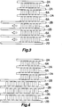
3 ist eine Ansicht, die ein Verfahren zum Anordnen von zwei Arten gewellter Lamellen des Kondensators von 1 zwischen angrenzenden Wärmeaustauschrohren zeigt, und einen Zustand zeigt, in welchem gewellte Lamellen der gleichen Art, konstruiert und hergestellt für kürzere Wärmeaustauschrohre, zwischen angrenzenden Wärmeaustauschrohren angeordnet werden; 3 FIG. 14 is a view illustrating a method of arranging two types of corrugated fins of the capacitor of FIG 1 between adjacent heat exchange tubes, and showing a state in which corrugated fins of the same kind, designed and manufactured for shorter heat exchange tubes, are placed between adjacent heat exchange tubes;
4 ist eine Ansicht, die einen Zustand zeigt, in welchem die gewellten Lamellen, die zwischen angrenzenden längeren Wärmeaustauschrohren angeordnet sind, in 3 gezeigt, verlängert wurden; 4 FIG. 14 is a view showing a state in which the corrugated fins disposed between adjacent longer heat exchange tubes in FIG 3 shown were extended;
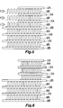
5 ist eine Ansicht, die ein Verfahren zum Anordnen von zwei Arten gewellter Lamellen des Kondensators von 1 zwischen angrenzenden Wärmeaustauschrohren zeigt, und einen Zustand zeigt, in welchem gewellte Lamellen der gleichen Art, konstruiert und hergestellt für längere Wärmeaustauschrohre, zwischen angrenzenden Wärmeaustauschrohren angeordnet werden; 5 FIG. 14 is a view illustrating a method of arranging two types of corrugated fins of the capacitor of FIG 1 between adjacent heat exchange tubes, and showing a state in which corrugated fins of the same kind, designed and manufactured for longer heat exchange tubes, are placed between adjacent heat exchange tubes;
6 ist eine Ansicht, die einen Zustand zeigt, in welchem die gewellten Lamellen, die zwischen angrenzenden kürzeren Wärmeaustauschrohren angeordnet sind, in 5 gezeigt, geschrumpft wurden; 6 FIG. 13 is a view showing a state in which the corrugated fins disposed between adjacent shorter heat exchange tubes in FIG 5 shown, shrunk;
7 ist eine Vorderansicht, die schematisch eine zweite Ausführungsform des Kondensators zeigt, an welchen der Wärmetauscher gemäß der vorliegenden Erfindung angewandt wird; und 7 is a front view schematically illustrating a second embodiment of Capacitor shows to which the heat exchanger according to the present invention is applied; and
8 ist eine Vorderansicht, die schematisch eine dritte Ausführungsform des Kondensators zeigt, an welchen der Wärmetauscher gemäß der vorliegenden Erfindung angewandt wird. 8th Fig. 16 is a front view schematically showing a third embodiment of the condenser to which the heat exchanger according to the present invention is applied.
BESCHREIBUNG DER BEVORZUGTEN AUSFÜHRUNGSFORMENDESCRIPTION OF THE PREFERRED EMBODIMENTS
Eine Ausführungsform der vorliegenden Erfindung wird als nächstes unter Bezugnahme auf die Zeichnungen beschrieben. Bei dieser Ausführungsform wird ein Wärmetauscher der vorliegenden Erfindung an einen Kondensator einer Autoklimaanlage angewandt, die an einem Automobil angebracht ist.An embodiment of the present invention will next be described with reference to the drawings. In this embodiment, a heat exchanger of the present invention is applied to a condenser of an automobile air conditioner mounted on an automobile.
In der folgenden Beschreibung wird die Rückseite eines Blatts auf welchem 1 gezeichnet ist, als die „vordere” bezeichnet, und die gegenüberliegende Seite als die „hintere”.In the following description, the back of a sheet on which 1 is drawn, referred to as the "front", and the opposite side as the "back".
Des Weiteren umfasst der Begriff „Aluminium”, wie er in der folgenden Beschreibung genutzt wird, Aluminiumlegierungen zusätzlich zu reinem Aluminium.Further, as used in the following description, the term "aluminum" includes aluminum alloys in addition to pure aluminum.
Gleiche Abschnitte und Komponenten werden durchweg in den Zeichnungen durch gleiche Bezugszeichen bezeichnet, und sie werden nicht redundant beschrieben.Like portions and components are denoted by like reference numerals throughout the drawings, and will not be described redundantly.
1 zeigt insbesondere die Gesamtstruktur einer ersten Ausführungsform eines Kondensators, an welchen ein Wärmetauscher gemäß der vorliegenden Erfindung angewandt ist, und 2 zeigt schematisch den Kondensator von 1. In 2 werden einzelne Wärmeaustauschrohre nicht dargestellt, und gewellte Lamellen, Seitenplatten, ein Kühlmittel-Einlasselement und ein Kühlmittel-Auslasselement werden auch nicht dargestellt. Die 3 bis 6 zeigen Verfahren zum Anordnen gewellter Lamellen zwischen angrenzenden Wärmeaustauschrohren. 1 shows in particular the overall structure of a first embodiment of a condenser to which a heat exchanger according to the present invention is applied, and 2 schematically shows the capacitor of 1 , In 2 individual heat exchange tubes are not shown, and corrugated fins, side plates, a refrigerant inlet member and a refrigerant outlet member are also not shown. The 3 to 6 show methods of arranging corrugated fins between adjacent heat exchange tubes.
Wie in den 1 und 2 gezeigt, umfasst ein Kondensator 1 eine Vielzahl flacher Wärmeaustauschrohre 2A, 2B, die aus Aluminium ausgebildet sind, drei Sammelbehälter bzw. Kopfbehälter 3, 4, 5, die aus Aluminium ausgebildet sind, gewellte Lamellen 6A, 6B, 6C, 6D, die aus Aluminium ausgebildet sind, und Seitenplatten 7, die aus Aluminium ausgebildet sind. Die Wärmeaustauschrohre 2A, 2B sind derart angeordnet, dass ihre Breitenrichtung mit einer vorne-hinten Richtung übereinstimmt, ihre Längsrichtung mit einer links-rechts Richtung übereinstimmt, und sie sind voneinander in einer vertikalen Richtung beabstandet. Die Sammelbehälter 3, 4, 5 sind derart angeordnet, dass ihre Längsrichtung mit der vertikalen Richtung übereinstimmt, und die linken und rechten Endabschnitte der Wärmeaustauschrohre 2A, 2B sind mit den Sammelbehältern 3, 4, 5 mittels Löten verbunden. Jede der gewellten Lamellen 6A ist zwischen angrenzenden Wärmeaustauschrohren 2A angeordnet und an sie gelötet. Jede der gewellten Lamellen 6B ist zwischen angrenzenden Wärmeaustauschrohren 2B angeordnet und an sie gelötet. Die gewellte Lamelle 6C ist an der Außenseite des obersten Austauschrohrs 2A angeordnet und ist daran gelötet. Die gewellte Lamelle 6D ist an der Außenseite des untersten Austauschrohrs 2B angeordnet und ist daran gelötet. Die Seitenplatten 7 sind an den entsprechenden Außenseiten der obersten und untersten gewellten Lamellen 6C, 6D angeordnet, und sind an diese gewellten Lamellen 6C, 6D gelötet.As in the 1 and 2 shown includes a capacitor 1 a variety of flat heat exchange tubes 2A . 2 B , which are formed of aluminum, three collecting containers or head container 3 . 4 . 5 made of aluminum, corrugated fins 6A . 6B . 6C . 6D which are formed of aluminum, and side plates 7 which are formed of aluminum. The heat exchange tubes 2A . 2 B are arranged such that their width direction coincides with a front-rear direction, their longitudinal direction coincides with a left-right direction, and they are spaced from each other in a vertical direction. The collection container 3 . 4 . 5 are arranged such that their longitudinal direction coincides with the vertical direction, and the left and right end portions of the heat exchange tubes 2A . 2 B are with the collection containers 3 . 4 . 5 connected by soldering. Each of the corrugated fins 6A is between adjacent heat exchange tubes 2A arranged and soldered to it. Each of the corrugated fins 6B is between adjacent heat exchange tubes 2 B arranged and soldered to it. The wavy lamella 6C is on the outside of the topmost replacement pipe 2A arranged and soldered to it. The wavy lamella 6D is on the outside of the bottom replacement pipe 2 B arranged and soldered to it. The side plates 7 are on the corresponding outsides of the top and bottom corrugated fins 6C . 6D arranged, and are at these corrugated fins 6C . 6D soldered.
Bei dem Kondensator 1 sind drei oder mehr Wärmeaustauschpfade (vier Wärmeaustauschpfade P1, P2, P3, P4 bei der vorliegenden Ausführungsform), jeder durch eine Vielzahl von aufeinanderfolgend in der vertikalen Richtung angeordneten Wärmeaustauschrohren 2A, 2B ausgebildet, in der vertikalen Richtung nebeneinander platziert. Die vier Wärmeaustauschpfade werden als die ersten bis vierten Wärmeaustauschpfade P1, P2, P3, P4 von der oberen Seite bezeichnet. Die Strömungsrichtung von Kühlmittel ist die gleiche unter sämtlichen der Wärmeaustauschrohre 2A, 2B, welche die jeweiligen Wärmeaustauschpfade P1, P2, P3, P4 ausbilden. Die Strömungsrichtung von Kühlmittel in den Wärmeaustauschrohren 2A, 2B, welchen einen bestimmten Wärmeaustauschpfad ausbilden, ist entgegensetzt der Strömungsrichtung von Kühlmittel in den Wärmeaustauschrohren 2A, 2B, welche einen anderen Wärmeaustauschpfad ausbilden, der angrenzend an den bestimmten Wärmeaustauschpfad ist. Die ersten und zweiten Wärmeaustauschpfade P1, P2 werden durch die Wärmeaustauschrohre 2A (nachfolgend als die ersten Wärmeaustauschrohre bezeichnet) der gleichen Art ausgebildet, welche die gleiche Länge aufweisen. Die dritten und vierten Wärmeaustauschpfade P3, P4 werden durch die Wärmeaustauschrohre 2B (nachfolgend als die zweiten Wärmeaustauschrohre bezeichnet) der gleichen Art ausgebildet, welche die gleiche Länge aufweisen.At the condenser 1 are three or more heat exchange paths (four heat exchange paths P1, P2, P3, P4 in the present embodiment) each through a plurality of heat exchange tubes sequentially arranged in the vertical direction 2A . 2 B formed, placed side by side in the vertical direction. The four heat exchange paths are referred to as the first to fourth heat exchange paths P1, P2, P3, P4 from the upper side. The flow direction of coolant is the same under all of the heat exchange tubes 2A . 2 B which form the respective heat exchange paths P1, P2, P3, P4. The flow direction of coolant in the heat exchange tubes 2A . 2 B which form a particular heat exchange path is opposite to the flow direction of refrigerant in the heat exchange tubes 2A . 2 B which form another heat exchange path that is adjacent to the particular heat exchange path. The first and second heat exchange paths P1, P2 are passed through the heat exchange tubes 2A (hereinafter referred to as the first heat exchange tubes) of the same type having the same length. The third and fourth heat exchange paths P3, P4 pass through the heat exchange tubes 2 B (hereinafter referred to as the second heat exchange tubes) of the same type having the same length.
Der Kondensator 1 weist nämlich eine erste Rohrgruppe G1 auf, die aus zumindest einem Wärmeaustauschpfad gebildet ist, umfassend den ersten Wärmeaustauschpfad P1 an dem oberen Ende (zwei Wärmeaustauschpfade bei der vorliegenden Ausführungsform; d. h. die ersten und zweiten Wärmeaustauschpfade P1, P2), und eine zweite Rohrgruppe G2, die unter der ersten Rohrgruppe G1 vorgesehen ist und aus zumindest einem Wärmeaustauschpfad gebildet ist, umfassend den vierten Wärmeaustauschpfad P4 an dem unteren Ende (zwei Wärmeaustauschpfade bei der vorliegenden Ausführungsform; d. h. die dritten und vierten Wärmeaustauschpfade P3, P4). Die zweiten Wärmeaustauschrohre 2B der zweiten Rohrgruppe G2 sind größer in der Länge als die ersten Wärmeaustauschrohre 2A der ersten Rohrgruppe G1. Bei der ersten Rohrgruppe G1 wird Kühlmittel dazu gebracht, von dem ersten Wärmeaustauschpfad P1 an dem oberen Ende zu dem zweiten Wärmeaustauschpfad P2 an dem unteren Ende hin zu strömen. Bei der zweiten Rohrgruppe G2 wird Kühlmittel dazu gebracht, von dem dritten Wärmeaustauschpfad P3 an dem oberen Ende zu dem vierten Wärmeaustauschpfad P4 an dem unteren Ende hin zu strömen. Das Kühlmittel, das durch die zwei Wärmeaustauschpfade P1, P2 der ersten Rohrgruppe G1 geströmt ist, wird dazu gebracht, durch die zwei Wärmeaustauschpfade P3, P4 der zweiten Rohrgruppe G2 zu strömen.The capacitor 1 Namely, has a first pipe group G1 formed of at least one heat exchange path including the first heat exchange path P1 at the upper end (two heat exchange paths in the present embodiment, ie, the first and second heat exchange paths P1, P2), and a second pipe group G2, which is provided below the first pipe group G1 and is formed of at least one heat exchange path including the fourth heat exchange path P4 at the lower end (two heat exchange paths in the present embodiment, ie, the third and fourth Heat exchange paths P3, P4). The second heat exchange tubes 2 B of the second pipe group G2 are larger in length than the first heat exchange pipes 2A the first pipe group G1. At the first pipe group G1, coolant is caused to flow from the first heat exchange path P1 at the upper end to the second heat exchange path P2 at the lower end. In the second pipe group G2, coolant is caused to flow from the third heat exchange path P3 at the upper end to the fourth heat exchange path P4 at the lower end. The refrigerant which has passed through the two heat exchange paths P1, P2 of the first pipe group G1 is made to flow through the two heat exchange paths P3, P4 of the second pipe group G2.
Der erste Sammelbehälter 3 und der zweite Sammelbehälter 4 sind einzeln an dem linken Ende des Kondensators 1 vorgesehen. Die ersten Wärmeaustauschrohre 2A der ersten und zweiten Wärmeaustauschpfade P1, P2 der ersten Rohrgruppe G1 sind mit dem ersten Sammelbehälter 3 mittels Löten verbunden. Die zweiten Wärmeaustauschrohre 2B der dritten und vierten Wärmeaustauschpfade P3, P4 der zweiten Rohrgruppe G2 sind mit dem zweiten Sammelbehälter 4 mittels Löten verbunden. Der zweite Sammelbehälter 4 ist an der Außenseite (linke Seite) des ersten Sammelbehälters 3 bezüglich der links-rechts Richtung angeordnet.The first collection container 3 and the second reservoir 4 are individually at the left end of the capacitor 1 intended. The first heat exchange tubes 2A the first and second heat exchange paths P1, P2 of the first pipe group G1 are connected to the first header tank 3 connected by soldering. The second heat exchange tubes 2 B the third and fourth heat exchange paths P3, P4 of the second pipe group G2 are connected to the second header tank 4 connected by soldering. The second collection container 4 is on the outside (left side) of the first collection container 3 arranged in the left-right direction.
Das obere Ende des zweiten Sammelbehälters 4 befindet sich über dem unteren Ende des ersten Sammelbehälters 3. Bei der vorliegenden Ausführungsform befindet sich das obere Ende des zweiten Sammelbehälters 4 an einer Position, welche im Wesentlichen die gleiche Höhe wie das obere Ende des ersten Sammelbehälters 3 aufweist. Das untere Ende des zweiten Sammelbehälters 4 befindet sich unter dem unteren Ende des ersten Sammelbehälters 3. Die zweiten Wärmeaustauschrohre 2B der dritten und vierten Wärmeaustauschpfade P3, P4 der zweiten Rohrgruppe G2 sind an einen Abschnitt des zweiten Sammelbehälters 4 gelötet, der sich unter dem ersten Sammelbehälter 3 befindet. Das innere Volumen des zweiten Sammelbehälters 4 wird derart bestimmt, dass sich ein Teil eines Gas-Flüssigkeit-Mischphasen-Kühlmittels, das in den zweiten Sammelbehälter 4 geströmt ist; d. h. Flüssigkeit-überwiegendes Mischphasen-Kühlmittel, aufgrund von Schwerkraft in einem unteren Bereich innerhalb des zweiten Sammelbehälters 4 ansammelt, und sich die Gasphasenkomponente des Gas-Flüssigkeit-Mischphasen-Kühlmittels aufgrund von Schwerkraft in einem oberen Bereich innerhalb des zweiten Sammelbehälters 4 ansammelt, wodurch lediglich das Flüssigkeit-überwiegende Mischphasen-Kühlmittel in die zweiten Wärmeaustauschrohre 2B des vierten Wärmeaustauschpfads P4 strömt. Folglich wirkt der zweite Sammelbehälter 4 als ein Flüssigkeitssammel- bzw. -aufnahmegefäß, welches Gas und Flüssigkeit durch Nutzen der Schwerkraft voneinander trennt und die Flüssigkeit speichert.The upper end of the second collection container 4 is located above the lower end of the first collection container 3 , In the present embodiment, the upper end of the second header tank is located 4 at a position substantially the same height as the upper end of the first header 3 having. The lower end of the second collection container 4 is located under the lower end of the first collection container 3 , The second heat exchange tubes 2 B the third and fourth heat exchange paths P3, P4 of the second pipe group G2 are connected to a portion of the second header tank 4 soldered, located under the first storage tank 3 located. The inner volume of the second collection container 4 is determined so that a portion of a gas-liquid mixed-phase refrigerant, which in the second collection container 4 has flowed; that is, liquid predominant mixed phase refrigerant due to gravity in a lower region within the second header 4 accumulates, and the gas phase component of the gas-liquid mixed-phase refrigerant due to gravity in an upper region within the second reservoir 4 accumulating, whereby only the liquid-predominant mixed-phase refrigerant in the second heat exchange tubes 2 B of the fourth heat exchange path P4 flows. Consequently, the second sump acts 4 as a liquid collecting vessel, which separates gas and liquid by utilizing gravity and stores the liquid.
Der dritte Sammelbehälter 5 ist an dem rechten Ende des Kondensators 1 angeordnet, und sämtliche der Wärmeaustauschrohre 2A, 2B, welche die ersten und zweiten Wärmeaustauschpfade P1, P2 der ersten Rohrgruppe G1 und die dritten und vierten Wärmeaustauschpfade P3, P4 der zweiten Rohrgruppe G2 ausbilden, sind mit dem dritten Sammelbehälter 5 verbunden. Folglich befinden sich die rechten Enden sämtlicher der Wärmeaustauschrohre 2A, 2B an ungefähr der gleichen Position.The third collection container 5 is at the right end of the capacitor 1 arranged, and all of the heat exchange tubes 2A . 2 B which form the first and second heat exchange paths P1, P2 of the first pipe group G1 and the third and fourth heat exchange paths P3, P4 of the second pipe group G2 are connected to the third header tank 5 connected. Thus, the right ends are all of the heat exchange tubes 2A . 2 B at about the same position.
Das Innere des dritten Sammelbehälters 5 ist in einen oberen Sammel- bzw. Kopfabschnitt 11, einen Zwischensammelabschnitt 12 und einen unteren Sammelabschnitt 13 durch Aluminium-Abtrennungsplatten 8, 9 unterteilt, welche an einer Höhe zwischen dem ersten Wärmeaustauschpfad P1 und dem zweiten Wärmeaustauschpfad P2 beziehungsweise einer Höhe zwischen dem dritten Wärmeaustauschpfad P3 und dem vierten Wärmeaustauschpfad P4 vorgesehen sind.The interior of the third storage tank 5 is in an upper header section 11 , an intermediate collection section 12 and a lower collection section 13 through aluminum separation plates 8th . 9 divided, which are provided at a height between the first heat exchange path P1 and the second heat exchange path P2 and a height between the third heat exchange path P3 and the fourth heat exchange path P4.
Ein Kühlmitteleinlass 14 ist an dem oberen Sammelabschnitt 11 des dritten Sammelbehälters 5 ausgebildet, und ein Kühlmittelauslass 15 ist an dem unteren Sammelabschnitt 13 des dritten Sammelbehälters 5 ausgebildet. Somit strömt, wie oben beschrieben, Kühlmittel von dem ersten Wärmeaustauschpfad P1 an dem oberen Ende zu dem zweiten Wärmeaustauschpfad P2 an dem unteren Ende in der ersten Rohrgruppe G1 hin, strömt von dem dritten Wärmeaustauschpfad P3 an dem oberen Ende zu dem vierten Wärmeaustauschpfad P4 an dem unteren Ende in der zweiten Rohrgruppe G2 hin. Das Kühlmittel, das durch die zwei Wärmeaustauschpfade P1, P2 der ersten Rohrgruppe G1 geströmt ist, strömt durch die zwei Wärmeaustauschpfade P3, P4 der zweiten Rohrgruppe G2. Ein Kühlmittel-Einlasselement 16, welches mit dem Kühlmitteleinlass 14 in Verbindung steht, und ein Kühlmittel-Auslasselement 17, welches mit dem Kühlmittelauslass 15 in Verbindung steht, sind an den dritten Sammelbehälter 5 gefügt.A coolant inlet 14 is at the upper collection section 11 of the third collection container 5 formed, and a coolant outlet 15 is at the lower collection section 13 of the third collection container 5 educated. Thus, as described above, coolant flows from the first heat exchange path P1 at the upper end to the second heat exchange path P2 at the lower end in the first pipe group G1, flows from the third heat exchange path P3 at the upper end to the fourth heat exchange path P4 at the first heat exchange path P3 lower end in the second tube group G2 out. The refrigerant that has passed through the two heat exchange paths P1, P2 of the first tube group G1 flows through the two heat exchange paths P3, P4 of the second tube group G2. A coolant inlet element 16 , which with the coolant inlet 14 communicates, and a coolant outlet element 17 , which with the coolant outlet 15 communicate with the third storage tank 5 together.
Der erste Sammelbehälter 3, ein Teil des zweiten Sammelbehälters 4, mit welchem die zweiten Wärmeaustauschrohre 23 des dritten Wärmeaustauschpfads P3 verbunden sind, der obere Sammelabschnitt 11 und Zwischensammelabschnitt 12 des dritten Sammelbehälters 5, und die ersten bis dritten Wärmeaustauschpfade P1–P3 bilden einen Kondensationsabschnitt 1A aus, welcher Kühlmittel kondensiert. Ein Teil des zweiten Sammelbehälters 4, mit welchem die zweiten Wärmeaustauschrohre 23 des vierten Wärmeaustauschpfads P4 verbunden sind, der untere Sammelabschnitt 13 des dritten Sammelbehälters 5, und der vierte Wärmeaustauschpfad P4 bilden einen Unterkühlungsabschnitt 13 aus, welcher Kühlmittel unterkühlt. Jeder der ersten und zweiten Wärmeaustauschpfade P1, P2 der ersten Rohrgruppe G1 und der dritte Wärmeaustauschpfad P3 des oberen Endes der zweiten Rohrgruppe G2 dient als ein Kühlmittel-Kondensationspfad zum Kondensieren von Kühlmittel, und der vierte Wärmeaustauschpfad P4 des unteren Endes der zweiten Rohrgruppe G2 dient als ein Kühlmittel-Unterkühlungspfad zum Unterkühlen von Kühlmittel.The first collection container 3 , a part of the second collection container 4 with which the second heat exchange tubes 23 of the third heat exchange path P3, the upper collecting portion 11 and intermediate collection section 12 of the third collection container 5 and the first to third heat exchange paths P1-P3 form a condensation section 1A from which condenses condensed coolant. Part of the second collection container 4 with which the second heat exchange tubes 23 of the fourth heat exchange path P4, the lower collecting portion 13 of the third collecting 5 , and the fourth heat exchange path P4 form a subcooling section 13 off, which undercooled coolant. Each of the first and second heat exchange paths P1, P2 of the first pipe group G1 and the third heat exchange path P3 of the upper end of the second pipe group G2 serves as a refrigerant condensation path for condensing refrigerant, and the fourth heat exchange path P4 of the lower end of the second pipe group G2 serves as a coolant subcooling path for subcooling coolant.
Gewellte Lamellen, welche kleiner in der Länge in der links-rechts Richtung sind; d. h. gewellte Lamellen 6A, jede zwischen angrenzenden ersten Wärmeaustauschrohren 2A der ersten Rohrgruppe G1 angeordnet, werden als erste gewellte Lamellen bezeichnet. Gewellte Lamellen, welche größer in der Länge in der links-rechts Richtung sind; d. h. gewellte Lamellen 6B, jede zwischen angrenzenden zweiten Wärmeaustauschrohren 2B der zweiten Rohrgruppe G2 angeordnet, werden als zweite gewellte Lamellen bezeichnet. Die gewellte Lamelle 6C, die an der oberen Seite des ersten Wärmeaustauschrohrs 2A an dem oberen Ende angeordnet ist, wird als eine dritte gewellte Lamelle bezeichnet. Die gewellte Lamelle 6D, die an der unteren Seite des zweiten Wärmeaustauschrohrs 2B an dem unteren Ende angeordnet ist, wird als eine vierte gewellte Lamelle bezeichnet. Bemerkenswerterweise ist die erste gewellte Lamelle 6A zwischen dem ersten Unteres-Ende-Wärmeaustauschrohr 2A bzw. dem ersten Wärmeaustauschrohr 2A des unteren Endes der ersten Rohrgruppe G1 und dem zweiten Oberes-Ende-Wärmeaustauschrohr 2A bzw. zweiten Wärmeaustauschrohr 2B des oberen Endes der zweiten Rohrgruppe G2 angeordnet. Da die zweiten Wärmeaustauschrohre 2B länger als die ersten Wärmeaustauschrohre 2A sind, ist die Länge der zweiten gewellten Lamellen 6B in der links-rechts Richtung größer als jene der ersten gewellten Lamellen 6A. Die Länge der dritten gewellten Lamelle 6C in der links-rechts Richtung ist kleiner als die Länge der ersten gewellten Lamellen 6A in der links-rechts Richtung. Die Länge der vierten gewellten Lamelle 6D in der links-rechts Richtung ist kleiner als die Länge der zweiten gewellten Lamellen 6B in der links-rechts Richtung und größer als die Länge der ersten gewellten Lamelle 6A in der links-rechts Richtung. Die Anzahl der Scheitelabschnitte von jeder der ersten und zweiten gewellten Lamellen 6A, 6B, die zwischen angrenzenden Wärmeaustauschrohren 2A, 2B angeordnet sind, fällt innerhalb eines Bereichs einer entworfenen Zahl (Standardzahl) ± 2. Der Abstand zwischen angrenzenden Scheitelabschnitten von jeder ersten gewellten Lamelle 6A ist kleiner als der Abstand zwischen angrenzenden Scheitelabschnitten von jeder zweiten gewellten Lamelle 6B. Die Anzahl der Scheitelabschnitte von jeder der dritten und vierten gewellten Lamellen 6C, 6D fällt innerhalb eines Bereichs einer entworfenen Zahl (Standardzahl) ± 2. Der Abstand zwischen angrenzenden Scheitelabschnitten von der dritten gewellten Lamelle 6C ist kleiner als der Abstand zwischen angrenzenden Scheitelabschnitten von jeder ersten gewellten Lamelle 6A, und der Abstand zwischen angrenzenden Scheitelabschnitten der vierten gewellten Lamelle 6D ist kleiner als der Abstand zwischen angrenzenden Scheitelabschnitten von jeder zweiten gewellten Lamelle 6B.Corrugated fins smaller in length in the left-right direction; ie corrugated fins 6A each between adjacent first heat exchange tubes 2A the first tube group G1 arranged, are referred to as first corrugated fins. Corrugated fins which are larger in length in the left-right direction; ie corrugated fins 6B each between adjacent second heat exchange tubes 2 B the second tube group G2 are referred to as second corrugated fins. The wavy lamella 6C located on the upper side of the first heat exchange tube 2A is disposed at the upper end, is referred to as a third corrugated fin. The wavy lamella 6D located on the lower side of the second heat exchange tube 2 B is disposed at the lower end is referred to as a fourth corrugated fin. Remarkably, the first corrugated fin 6A between the first lower-end heat exchange tube 2A or the first heat exchange tube 2A the lower end of the first pipe group G1 and the second upper-end heat exchange pipe 2A or second heat exchange tube 2 B the upper end of the second tube group G2 arranged. Because the second heat exchange tubes 2 B longer than the first heat exchange tubes 2A are the length of the second corrugated fins 6B in the left-right direction larger than that of the first corrugated fins 6A , The length of the third wavy lamella 6C in the left-right direction is smaller than the length of the first corrugated fins 6A in the left-right direction. The length of the fourth wavy lamella 6D in the left-right direction is smaller than the length of the second corrugated fins 6B in the left-right direction and larger than the length of the first wavy lamella 6A in the left-right direction. The number of vertex sections of each of the first and second corrugated fins 6A . 6B between adjacent heat exchange tubes 2A . 2 B The distance between adjacent apex portions of each first corrugated fin falls within a range of a designed number (standard number) ± 2 6A is smaller than the distance between adjacent apex portions of every other corrugated fin 6B , The number of vertex sections of each of the third and fourth corrugated fins 6C . 6D falls within a range of a designed number (standard number) ± 2. The distance between adjacent vertex sections of the third wavy louver 6C is smaller than the distance between adjacent apex portions of each first corrugated fin 6A , and the distance between adjacent apex portions of the fourth corrugated fin 6D is smaller than the distance between adjacent apex portions of every other corrugated fin 6B ,
Die ersten und zweiten gewellten Lamellen 6A, 6B sind gewellte Lamellen von einer Art, welche unter der gleichen Bedingung konstruiert und hergestellt sind. Zwei Fälle existieren; d. h. der Fall wo die zweiten gewellten Lamellen 6B, die für die Länge der längeren zweiten Wärmeaustauschrohre 2B geeignet sind, aus den ersten gewellten Lamellen 6A von einer Art angefertigt werden, welche unter der Bedingung konstruiert und hergestellt sind, die für die Länge der kürzeren ersten Wärmeaustauschrohre 2A geeignet ist; und der Fall wo die ersten gewellten Lamellen 6A, die für die Länge der kürzeren ersten Wärmeaustauschrohre 2A geeignet sind, aus den zweiten gewellten Lamellen 6B von einer Art angefertigt werden, welche unter der Bedingung konstruiert und hergestellt sind, die für die Länge der längeren zweiten Wärmeaustauschrohre 2B geeignet ist. Bemerkenswerterweise besteht ein Fall in Bezug auf die dritten und die vierten gewellten Lamellen 6C, 6D, wie in dem oben beschriebenen Fall, wo sie aus den ersten gewellten Lamellen 6A von einer Art angefertigt werden, und der Fall wo sie aus den zweiten gewellten Lamellen 6B von einer Art angefertigt werden.The first and second corrugated fins 6A . 6B are corrugated fins of a type that are designed and manufactured under the same condition. Two cases exist; ie the case where the second corrugated fins 6B that is responsible for the length of the longer second heat exchange tubes 2 B are suitable from the first corrugated fins 6A of a type constructed and manufactured under the condition corresponding to the length of the shorter first heat exchange tubes 2A suitable is; and the case where the first corrugated fins 6A that is responsible for the length of the shorter first heat exchange tubes 2A are suitable from the second corrugated fins 6B of a type constructed and manufactured under the condition necessary for the length of the longer second heat exchange tubes 2 B suitable is. Remarkably, there is a case with respect to the third and fourth corrugated fins 6C . 6D as in the case described above, where they consist of the first corrugated fins 6A made of a kind, and the case where they are made from the second corrugated fins 6B be made of a kind.
In dem Fall der Verwendung der ersten gewellten Lamellen 6A, die unter der für die Länge der kürzeren ersten Wärmeaustauschrohre 2A geeigneten Bedingung konstruiert und hergestellt sind, wie in 3 gezeigt, wird jede der ersten gewellten Lamellen 6A zuerst zwischen angrenzenden ersten Wärmeaustauschrohren 2A, zwischen angrenzenden zweiten Wärmeaustauschrohren 2B, oder zwischen dem ersten Wärmeaustauschrohr 2A des unteren Endes und dem zweiten Wärmeaustauschrohr 2B des oberen Endes angeordnet. Zu dem Zeitpunkt befinden sich die rechten Enden der Wärmeaustauschrohre 2A, 2B im Wesentlichen in der gleichen Position, und die rechten Enden der ersten gewellten Lamellen 6A befinden sich auch im Wesentlichen in der gleichen Position. Nachfolgend wird, wie in 4 gezeigt, jede erste gewellte Lamelle 6A, die zwischen angrenzenden zweiten Wärmeaustauschrohren 2B angeordnet ist, derart gedehnt bzw. verlängert, dass ihr linkes Ende eine Position nahe den linken Enden der zweiten Wärmeaustauschrohre 2B erreicht, wodurch der Abstand zwischen angrenzenden Scheitelabschnitten der ersten gewellten Lamellen 6A größer gemacht wird als derjenige bevor die ersten gewellten Lamellen 6A verlängert wurden. Auf diese Art und Weise werden die zweiten gewellten Lamellen 6B aus den ersten gewellten Lamellen 6A angefertigt. Bemerkenswerterweise werden die dritten und vierten gewellten Lamellen 6C, 6D auch aus den ersten gewellten Lamellen 6A angefertigt, auf eine Art ähnlich derjenigen, die oben beschrieben ist.In the case of using the first corrugated fins 6A under the length of the shorter first heat exchange tubes 2A suitable condition are constructed and manufactured as in 3 shown, each of the first corrugated fins 6A first between adjacent first heat exchange tubes 2A between adjacent second heat exchange tubes 2 B , or between the first heat exchange tube 2A the lower end and the second heat exchange tube 2 B the upper end arranged. At the time, the right ends of the heat exchange tubes are located 2A . 2 B essentially in the same position, and the right ends of the first corrugated fins 6A are also essentially in the same position. The following will, as in 4 shown, every first wavy lamella 6A between adjacent second heat exchange tubes 2 B is disposed so elongated that its left end a position near the left ends of the second heat exchange tubes 2 B achieved, whereby the distance between adjacent vertex sections of the first corrugated fins 6A made larger than the one before the first corrugated fins 6A were extended. In this way, the second corrugated slats 6B from the first corrugated fins 6A prepared. Remarkably, the third and fourth corrugated fins 6C . 6D also from the first corrugated fins 6A made in a manner similar to that described above.
In dem Fall der Verwendung der zweiten gewellten Lamellen 6B, die unter der für die Länge der längeren zweiten Wärmeaustauschrohre 2B geeigneten Bedingung konstruiert und hergestellt sind, wie in 5 gezeigt, wird jede der zweiten gewellten Lamellen 6B zuerst zwischen angrenzenden ersten Wärmeaustauschrohren 2A, zwischen angrenzenden zweiten Wärmeaustauschrohren 2B, oder zwischen dem ersten Wärmeaustauschrohr 2A des unteren Endes und dem zweiten Wärmeaustauschrohr 2B des oberen Endes angeordnet. Zu dem Zeitpunkt befinden sich die rechten Enden der Wärmeaustauschrohre 2A, 2B im Wesentlichen in der gleichen Position, und die rechten Enden der zweiten gewellten Lamellen 6B befinden sich auch im Wesentlichen in der gleichen Position. Nachfolgend wird, wie in 6 gezeigt, jede zweite gewellte Lamelle 6B, die zwischen angrenzenden ersten Wärmeaustauschrohren 2A angeordnet ist, und die zweite gewellte Lamelle 6B, die zwischen dem ersten Wärmeaustauschrohr 2A des unteren Endes und dem zweiten Wärmeaustauschrohr 2B des oberen Endes angeordnet ist, derart nach rechts zusammengepresst bzw. gestaucht, dass ihre linken Enden eine Position nahe den linken Enden der ersten Wärmeaustauschrohre 2A erreichen, wodurch der Abstand zwischen angrenzenden Scheitelabschnitten der zweiten gewellten Lamellen 6B kleiner gemacht wird als derjenige bevor die zweiten gewellten Lamellen 6B zusammengepresst wurden. Auf diese Art und Weise werden die ersten gewellten Lamellen 6A aus den zweiten gewellten Lamellen 6B angefertigt. Bemerkenswerterweise werden die dritten und vierten gewellten Lamellen 6C, 6D auch aus den zweiten gewellten Lamellen 6B angefertigt, auf eine Art ähnlich derjenigen, die oben beschrieben ist.In the case of using the second corrugated fins 6B under the length of the longer second heat exchange tubes 2 B suitable condition are constructed and manufactured as in 5 shown, each of the second corrugated fins 6B first between adjacent first heat exchange tubes 2A between adjacent second heat exchange tubes 2 B , or between the first heat exchange tube 2A the lower end and the second heat exchange tube 2 B the upper end arranged. At the time, the right ends of the heat exchange tubes are located 2A . 2 B essentially in the same position, and the right ends of the second corrugated fins 6B are also essentially in the same position. The following will, as in 6 shown, every second corrugated lamella 6B between adjacent first heat exchange tubes 2A is arranged, and the second corrugated fin 6B between the first heat exchange tube 2A the lower end and the second heat exchange tube 2 B of the upper end is so compressed or compressed that its left ends a position near the left ends of the first heat exchange tubes 2A reach, whereby the distance between adjacent vertex sections of the second corrugated fins 6B made smaller than the one before the second corrugated fins 6B were pressed together. In this way, the first corrugated fins are 6A from the second corrugated fins 6B prepared. Remarkably, the third and fourth corrugated fins 6C . 6D also from the second corrugated fins 6B made in a manner similar to that described above.
Der Kondensator 1 wird durch Zusammenlöten sämtlicher Komponenten hergestellt.The capacitor 1 is made by soldering together all the components.
Der Kondensator 1 bildet einen Kältekreislauf in Zusammenarbeit mit einem Kompressor, einem Expansionsventil (Druckminderer) und einem Verdampfer; und der Kältekreislauf ist an einem Fahrzeug als eine Autoklimaanlage montiert.The capacitor 1 Forms a refrigeration circuit in cooperation with a compressor, an expansion valve (pressure reducer) and an evaporator; and the refrigeration cycle is mounted on a vehicle as a car air conditioner.
Bei dem Kondensator 1 mit der oben beschriebenen Struktur strömt Gasphasen-Kühlmittel mit hoher Temperatur und hohem Druck, komprimiert durch den Kompressor, in den oberen Sammelabschnitt 11 des dritten Sammelbehälters 5 über das Kühlmittel-Einlasselement 16 und den Kühlmitteleinlass 14. Das Gasphasen-Kühlmittel wird kondensiert, während es innerhalb der ersten Wärmeaustauschrohre 2A des ersten Wärmeaustauschpfads P1 nach links strömt, und strömt dann in den ersten Sammelbehälter 3. Das Kühlmittel, das in den ersten Sammelbehälter 3 geströmt ist, wird kondensiert, während es innerhalb der ersten Wärmeaustauschrohre 2A des zweiten Wärmeaustauschpfads P2 nach rechts strömt, und strömt dann in den Zwischensammelabschnitt 12 des dritten Sammelbehälters 5. Das Kühlmittel, das in den Zwischensammelabschnitt 12 des dritten Sammelbehälters 5 geströmt ist, wird kondensiert, während es innerhalb der zweiten Wärmeaustauschrohre 2B des dritten Wärmeaustauschpfads P3 nach links strömt, und strömt dann in den zweiten Sammelbehälter 4.At the condenser 1 With the structure described above, high-temperature and high-pressure gas-phase refrigerant compressed by the compressor flows into the upper collecting portion 11 of the third collection container 5 via the coolant inlet element 16 and the coolant inlet 14 , The gas phase refrigerant is condensed while inside the first heat exchange tube 2A of the first heat exchange path P1 flows to the left, and then flows into the first header tank 3 , The coolant that is in the first collection tank 3 has flowed, while it is condensing within the first heat exchange tubes 2A of the second heat exchange path P2 flows to the right, and then flows into the intermediate header section 12 of the third collection container 5 , The coolant entering the intermediate collection section 12 of the third collection container 5 has flowed, while it is condensed within the second heat exchange tubes 2 B of the third heat exchange path P3 flows to the left, and then flows into the second header tank 4 ,
Das Kühlmittel, das in den zweiten Sammelbehälter 4 geströmt ist, ist Gas-Flüssigkeit-Mischphasen-Kühlmittel. Ein Teil des Gas-Flüssigkeit-Mischphasen-Kühlmittels; d. h. Flüssigkeit-überwiegendes Mischphasen-Kühlmittel, sammelt sich in einem unteren Bereich innerhalb des zweiten Sammelbehälters 4 aufgrund von Schwerkraft, und tritt in die zweiten Wärmeaustauschrohre 2B des vierten Wärmeaustauschpfads P4 ein.The coolant entering the second sump 4 has flowed is gas-liquid mixed-phase refrigerant. A portion of the gas-liquid mixed-phase refrigerant; that is, liquid predominant mixed phase refrigerant collects in a lower region within the second header tank 4 due to gravity, and enters the second heat exchange tubes 2 B of the fourth heat exchange path P4.
Das Flüssigkeit-überwiegende Mischphasen-Kühlmittel, das in die zweiten Wärmeaustauschrohre 2B des vierten Wärmeaustauschpfads P4 eingetreten ist, wird unterkühlt, während es innerhalb der zweiten Wärmeaustauschrohre 2B nach rechts strömt. Danach tritt das unterkühlte Kühlmittel in den unteren Sammelabschnitt 13 des dritten Sammelbehälters 5 ein, und strömt über den Kühlmittelauslass 15 und das Kühlmittel-Auslasselement 17 heraus. Das Kühlmittel wird dann über das Expansionsventil an den Verdampfer gespeist.The liquid-predominant mixed-phase refrigerant entering the second heat exchange tubes 2 B of the fourth heat exchange path P4 is supercooled while inside the second heat exchange tube 2 B flows to the right. Thereafter, the supercooled coolant enters the lower collection section 13 of the third collection container 5 and flows over the coolant outlet 15 and the coolant outlet member 17 out. The coolant is then fed via the expansion valve to the evaporator.
Währenddessen sammelt sich die Gasphasen-Komponente des Gas-Flüssigkeit-Mischphasen-Kühlmittels, das in den zweiten Sammelbehälter 4 geströmt ist, in einem oberen Bereich innerhalb des zweiten Sammelbehälters 4.Meanwhile, the gas phase component of the gas-liquid mixed-phase refrigerant that accumulates in the second header collects 4 has flowed in an upper area within the second header tank 4 ,
7 und 8 zeigen andere Ausführungsformen des Kondensators, an welchem der Wärmetauscher der vorliegenden Erfindung angewandt ist. In den 7 und 8, von denen jede schematisch einen Kondensator zeigt, werden einzelne Wärmeaustauschrohre nicht dargestellt, und gewellte Lamellen, Seitenplatten, ein Kühlmittel-Einlasselement und ein Kühlmittel-Auslasselement werden auch nicht dargestellt. 7 and 8th show other embodiments of the capacitor to which the heat exchanger of the present invention is applied. In the 7 and 8th each of which schematically shows a condenser, individual heat exchange tubes are not shown, and corrugated fins, side plates, a refrigerant inlet member and a refrigerant outlet member are also not shown.
In dem Fall des in 7 gezeigten Kondensators 20 sind vier Wärmeaustauschpfade P1, P2, P3, P4, jeder durch eine Vielzahl von aufeinanderfolgend in der vertikalen Richtung angeordneten Wärmeaustauschrohren 2A, 2B ausgebildet, die in der vertikalen Richtung nebeneinander platziert sind. Die drei Wärmeaustauschpfade an der oberen Seite werden als die ersten bis dritten Wärmeaustauschpfade P1, P2, P3 von der unteren Seite bezeichnet, und der Wärmeaustauschpfad an dem unteren Ende wird als der vierte Wärmeaustauschpfad P4 bezeichnet. Die Strömungsrichtung von Kühlmittel ist die gleiche unter sämtlichen der Wärmeaustauschrohre 2A, 2B, welche die jeweiligen Wärmeaustauschpfade P1, P2, P3, P4 ausbilden. Die Strömungsrichtung von Kühlmittel in den Wärmeaustauschrohren 2A, 2B, welchen einen bestimmten Wärmeaustauschpfad ausbilden, ist entgegensetzt der Strömungsrichtung von Kühlmittel in den Wärmeaustauschrohren 2A, 2B, welche einen anderen Wärmeaustauschpfad ausbilden, der angrenzend an den bestimmten Wärmeaustauschpfad ist. Die ersten und zweiten Wärmeaustauschpfade P1, P2 werden durch die ersten Wärmeaustauschrohre 2A der gleichen Art ausgebildet, welche die gleiche Länge aufweisen. Die dritten und vierten Wärmeaustauschpfade P3, P4 werden durch die zweiten Wärmeaustauschrohre 23 der gleichen Art ausgebildet, welche die gleiche Länge aufweisen.In the case of in 7 shown capacitor 20 are four heat exchange paths P1, P2, P3, P4, each through a plurality of heat exchange tubes sequentially arranged in the vertical direction 2A . 2 B formed, which are placed side by side in the vertical direction. The three heat exchange paths on the upper side are referred to as the first to third heat exchange paths P1, P2, P3 from the lower side, and the heat exchange path at the lower end is referred to as the fourth heat exchange path P4. The flow direction of coolant is the same under all of the heat exchange tubes 2A . 2 B which form the respective heat exchange paths P1, P2, P3, P4. The flow direction of coolant in the heat exchange tubes 2A . 2 B which form a particular heat exchange path is opposite to the flow direction of refrigerant in the heat exchange tubes 2A . 2 B which form another heat exchange path that is adjacent to the particular heat exchange path. The first and second heat exchange paths P1, P2 are passed through the first heat exchange tubes 2A formed of the same type, which have the same length. The third and fourth heat exchange paths P3, P4 are passed through the second heat exchange tubes 23 formed of the same type, which have the same length.
Der Kondensator 20 weist nämlich eine erste Rohrgruppe G1 auf, die aus den ersten und zweiten Wärmeaustauschpfaden P1, P2 gebildet ist; eine zweite Rohrgruppe G2, die über der ersten Rohrgruppe G1 vorgesehen ist, und aus dem dritten Wärmeaustauschpfad P3 an dem oberen Ende gebildet ist; und eine dritte Rohrgruppe G3, die unter der ersten Rohrgruppe G1 vorgesehen ist, und aus dem vierten Wärmeaustauschpfad P4 an dem unteren Ende gebildet ist. Die zweiten Wärmeaustauschrohre 2B der zweiten und dritten Rohrgruppen G2, G3 sind größer in der Länge als die ersten Wärmeaustauschrohre 2A der ersten Rohrgruppe G1. Bei der ersten Rohrgruppe G1 wird Kühlmittel dazu gebracht, von dem ersten Wärmeaustauschpfad P1 an dem unteren Ende zu dem zweiten Wärmeaustauschpfad P2 an dem oberen Ende hin zu strömen. Das Kühlmittel, das durch die zwei Wärmeaustauschpfade P1, P2 der ersten Rohrgruppe G1 geströmt ist, wird dazu gebracht, durch den dritten Wärmeaustauschpfad P3 der zweiten Rohrgruppe G2 und den vierten Wärmeaustauschpfad P4 der dritten Rohrgruppe G3, in dieser Reihenfolge, zu strömen.The capacitor 20 namely, has a first pipe group G1 formed of the first and second heat exchange paths P1, P2; a second pipe group G2 provided above the first pipe group G1 and formed of the third heat exchange path P3 at the upper end; and a third pipe group G3 provided below the first pipe group G1 and formed of the fourth heat exchange path P4 at the lower end. The second heat exchange tubes 2 B the second and third pipe groups G2, G3 are larger in length than the first heat exchange pipes 2A the first pipe group G1. In the first pipe group G1, coolant is caused to flow from the first heat exchange path P1 at the lower end to the second heat exchange path P2 at the upper end. The refrigerant that has passed through the two heat exchange paths P1, P2 of the first pipe group G1 is caused to flow through the third heat exchange path P3 of the second pipe group G2 and the fourth heat exchange path P4 of the third pipe group G3, in that order.
Ein erster Sammelbehälter 3 und ein zweiter Sammelbehälter 4 sind einzeln an dem linken Ende des Kondensators 20 vorgesehen. Die ersten Wärmeaustauschrohre 2A der ersten und zweiten Wärmeaustauschpfade P1, P2 der ersten Rohrgruppe G1 sind mit dem ersten Sammelbehälter 3 mittels Löten verbunden. Die zweiten Wärmeaustauschrohre 2B der dritten und vierten Wärmeaustauschpfade P3, P4 der zweiten und dritten Rohrgruppen G2, G3 sind mit dem zweiten Sammelbehälter 4 mittels Löten verbunden. Der zweite Sammelbehälter 4 ist an der Außenseite (linke Seite) des ersten Sammelbehälters 3 bezüglich der links-rechts Richtung angeordnet. Das obere Ende des zweiten Sammelbehälters 4, der an dem linken Ende des Kondensators 20 angeordnet ist, befindet sich über dem unteren Ende des ersten Sammelbehälters 3, und das untere Ende des zweiten Sammelbehälters 4 befindet sich unter dem unteren Ende des ersten Sammelbehälters 3. Die ersten Wärmeaustauschrohre 2A der ersten und zweiten Wärmeaustauschpfade P1, P2 der ersten Rohrgruppe G1 sind an den ersten Sammelbehälter 3 gelötet. Die zweiten Wärmeaustauschrohre 2B des dritten Wärmeaustauschpfads P3 der zweiten Rohrgruppe G2 sind an einen Abschnitt des zweiten Sammelbehälters 4 gelötet, der sich über dem ersten Sammelbehälter 3 befindet. Die zweiten Wärmeaustauschrohre 2B des vierten Wärmeaustauschpfads P4 der dritten Rohrgruppe G3 sind an einen Abschnitt des zweiten Sammelbehälters 4 gelötet, der sich unter dem ersten Sammelbehälter 3 befindet.A first collection container 3 and a second collection container 4 are individually at the left end of the capacitor 20 intended. The first heat exchange tubes 2A the first and second heat exchange paths P1, P2 of the first pipe group G1 are connected to the first header tank 3 connected by soldering. The second heat exchange tubes 2 B the third and fourth heat exchange paths P3, P4 of the second and third pipe groups G2, G3 are connected to the second header tank 4 connected by soldering. The second collection container 4 is on the outside (left side) of the first collection container 3 arranged in the left-right direction. The upper end of the second collection container 4 at the left end of the capacitor 20 is located above the lower end of the first collection container 3 , and the lower end of the second collection container 4 is located under the lower end of the first collection container 3 , The first heat exchange tubes 2A the first and second heat exchange paths P1, P2 of the first pipe group G1 are to the first header tank 3 soldered. The second heat exchange tubes 2 B of the third heat exchange path P3 of the second pipe group G2 are to a portion of the second header tank 4 soldered, which is above the first collection container 3 located. The second heat exchange tubes 2 B of the fourth heat exchange path P4 of the third pipe group G3 are to a portion of the second header tank 4 soldered, located under the first storage tank 3 located.
Das innere Volumen des zweiten Sammelbehälters 4 wird derart bestimmt, dass sich ein Teil eines Gas-Flüssigkeit-Mischphasen-Kühlmittels, das in den zweiten Sammelbehälter 4 geströmt ist; d. h. Flüssigkeit-überwiegendes Mischphasen-Kühlmittel, aufgrund von Schwerkraft in einem unteren Bereich innerhalb des zweiten Sammelbehälters 4 ansammelt, und sich die Gasphasenkomponente des Gas-Flüssigkeit-Mischphasen-Kühlmittels aufgrund von Schwerkraft in einem oberen Bereich innerhalb des zweiten Sammelbehälters 4 ansammelt, wodurch lediglich das Flüssigkeit-überwiegende Mischphasen-Kühlmittel in die zweiten Wärmeaustauschrohre 2B des vierten Wärmeaustauschpfads P4 strömt. Folglich wirkt der zweite Sammelbehälter 4 als ein Flüssigkeitssammelgefäß, welches Gas und Flüssigkeit durch Nutzen der Schwerkraft voneinander trennt und die Flüssigkeit speichert.The inner volume of the second collection container 4 is determined so that a portion of a gas-liquid mixed-phase refrigerant, which in the second collection container 4 has flowed; that is, liquid predominant mixed phase refrigerant due to gravity in a lower region within the second header 4 accumulates, and the gas phase component of the gas-liquid mixed-phase refrigerant due to gravity in an upper region within the second reservoir 4 accumulating, whereby only the liquid-predominant mixed-phase refrigerant in the second heat exchange tubes 2 B of the fourth heat exchange path P4 flows. Consequently, the second sump acts 4 as a liquid collecting vessel, which separates gas and liquid by utilizing gravity and stores the liquid.
Das Innere eines dritten Sammelbehälters 5, mit welchem die rechten Enden sämtlicher der Wärmeaustauschrohre 2A, 2B mittels Löten verbunden sind, ist in einen Zwischensammelabschnitt 23, einen oberen Sammelabschnitt 24 und einen unteren Sammelabschnitt 25 durch Aluminium-Abtrennungsplatten 21, 22 unterteilt, welche an einer Höhe zwischen dem ersten Wärmeaustauschpfad P1 und dem zweiten Wärmeaustauschpfad P2 beziehungsweise einer Höhe zwischen dem ersten Wärmeaustauschpfad P1 und dem vierten Wärmeaustauschpfad P4 vorgesehen sind. Ein Kühlmitteleinlass 14 ist an dem unteren Ende des Zwischensammelabschnitts 23 des dritten Sammelbehälters 5 ausgebildet, und ein Kühlmittelauslass 15 ist an dem unteren Sammelabschnitt 25 des dritten Sammelbehälters 5 ausgebildet. Die rechten Enden der ersten Wärmeaustauschrohre 2A des ersten Wärmeaustauschpfads P1 sind mit dem Zwischensammelabschnitt 23 des dritten Sammelbehälters 5 verbunden. Die rechten Enden der ersten Wärmeaustauschrohre 2A des zweiten Wärmeaustauschpfads P2 sind mit dem oberen Sammelabschnitt 24 des dritten Sammelbehälters 5 verbunden. Die rechten Enden der zweiten Wärmeaustauschrohre 2B des dritten Wärmeaustauschpfad P3 sind mit dem oberen Sammelabschnitt 24 des dritten Sammelbehälters 5 verbunden. Die rechten Enden der zweiten Wärmeaustauschrohre 2B des vierten Wärmeaustauschpfads P4 sind mit dem unteren Sammelabschnitt 25 des dritten Sammelbehälters 5 verbunden. Ein Kühlmittel-Einlasselement (nicht gezeigt), welches mit dem Kühlmitteleinlass 14 in Verbindung steht, und ein Kühlmittel-Auslasselement (nicht gezeigt), welches mit dem Kühlmittelauslass 15 in Verbindung steht, sind an den dritten Sammelbehälter 5 angefügt.The interior of a third storage tank 5 with which the right ends of all of the heat exchange tubes 2A . 2 B connected by soldering, is in an intermediate collecting section 23 , an upper collection section 24 and a lower collection section 25 through aluminum separation plates 21 . 22 divided, which are provided at a height between the first heat exchange path P1 and the second heat exchange path P2 and a height between the first heat exchange path P1 and the fourth heat exchange path P4. A coolant inlet 14 is at the lower end of the intermediate collecting section 23 of the third collection container 5 formed, and a coolant outlet 15 is at the lower collection section 25 of the third collection container 5 educated. The right ends of the first heat exchange tubes 2A of the first heat exchange path P1 are connected to the intermediate header section 23 of the third collecting 5 connected. The right ends of the first heat exchange tubes 2A of the second heat exchange path P2 are with the upper collecting portion 24 of the third collection container 5 connected. The right ends of the second heat exchange tubes 2 B of the third heat exchange path P3 are connected to the upper collecting portion 24 of the third collection container 5 connected. The right ends of the second heat exchange tubes 2 B of the fourth heat exchange path P4 are connected to the lower collecting portion 25 of the third collection container 5 connected. A coolant inlet member (not shown) connected to the coolant inlet 14 and a coolant outlet member (not shown) connected to the coolant outlet 15 communicate with the third storage tank 5 added.
Der erste Sammelbehälter 3, ein Teil des zweiten Sammelbehälters 4, mit welchem die zweiten Wärmeaustauschrohre 2B des dritten Wärmeaustauschpfads P3 verbunden sind, der Zwischensammelabschnitt 23 und obere Sammelabschnitt 24 des dritten Sammelbehälters 5, und die ersten bis dritten Wärmeaustauschpfade P1–P3 bilden einen Kondensationsabschnitt 20A aus, welcher Kühlmittel kondensiert. Ein Teil des zweiten Sammelbehälters 4, mit welchem die zweiten Wärmeaustauschrohre 2B des vierten Wärmeaustauschpfads P4 verbunden sind, der untere Sammelabschnitt 25 des dritten Sammelbehälters 5, und der vierte Wärmeaustauschpfad P4 bilden einen Unterkühlungsabschnitt 20B aus, welcher Kühlmittel unterkühlt. Jeder der ersten und zweiten Wärmeaustauschpfade P1, P2 der ersten Rohrgruppe G1 und der dritte Wärmeaustauschpfad P3 des oberen Endes der zweiten Rohrgruppe G2 dient als ein Kühlmittel-Kondensationspfad zum Kondensieren von Kühlmittel, und der vierte Wärmeaustauschpfad P4 der dritten Rohrgruppe G3 dient als ein Kühlmittel-Unterkühlungspfad zum Unterkühlen von Kühlmittel.The first collection container 3 , a part of the second collection container 4 with which the second heat exchange tubes 2 B of the third heat exchange path P3, the intermediate collecting portion 23 and upper collection section 24 of the third collection container 5 and the first to third heat exchange paths P1-P3 form a condensation section 20A from which condenses condensed coolant. Part of the second collection container 4 with which the second heat exchange tubes 2 B of the fourth heat exchange path P4, the lower collecting portion 25 of the third collection container 5 , and the fourth heat exchange path P4 form a subcooling section 20B off, which undercooled coolant. Each of the first and second heat exchange paths P1, P2 of the first pipe group G1 and the third heat exchange path P3 of the upper end of the second pipe group G2 serves as a refrigerant condensation path for condensing refrigerant, and the fourth heat exchange path P4 of the third pipe group G3 serves as a refrigerant. Subcooling path for subcooling coolant.
Obwohl es in den Zeichnungen nicht dargestellt ist, sind erste gewellte Lamellen 6A, welche kleiner in der Länge in der links-rechts Richtung sind, zwischen angrenzenden ersten Wärmeaustauschrohren 2A der ersten Rohrgruppe G1 angeordnet, zwischen dem ersten Wärmeaustauschrohr 2A des oberen Endes der ersten Rohrgruppe G1 und dem zweiten Wärmeaustauschrohr 2B des unteren Endes der zweiten Rohrgruppe G2, und zwischen dem ersten Wärmeaustauschrohr 2A des unteren Endes der ersten Rohrgruppe G1 und dem zweiten Wärmeaustauschrohr 2B des oberen Endes der dritten Rohrgruppe G3. Auch sind zweite gewellte Lamellen 6B, welche größer in der Länge in der links-rechts Richtung sind, zwischen angrenzenden zweiten Wärmeaustauschrohren 2B der zweiten und dritten Rohrgruppen G2, G3 angeordnet. Die Anzahl der Scheitelabschnitte von jeder der sämtlichen der ersten und zweiten gewellten Lamellen 6A, 6B fällt innerhalb eines Bereichs einer entworfenen Zahl (Standardzahl) ± 2. Der Abstand zwischen angrenzenden Scheitelabschnitten von jeder ersten gewellten Lamelle 6A ist kleiner als der Abstand zwischen angrenzenden Scheitelabschnitten von jeder zweiten gewellten Lamelle 6B. Wie in dem Fall der oben beschriebenen ersten Ausführungsform, sind die ersten und zweiten gewellten Lamellen 6A, 6B gewellte Lamellen von einer Art, welche unter der gleichen Bedingung konstruiert und hergestellt sind.Although not shown in the drawings, first corrugated fins are 6A which are smaller in length in the left-right direction, between adjacent first heat exchange tubes 2A the first tube group G1, disposed between the first heat exchange tube 2A the upper end of the first pipe group G1 and the second heat exchange pipe 2 B the lower end of the second tube group G2, and between the first heat exchange tube 2A the lower end of the first pipe group G1 and the second heat exchange pipe 2 B the upper end of the third pipe group G3. Also are second corrugated fins 6B which are larger in length in the left-right direction, between adjacent second heat exchange tubes 2 B the second and third pipe groups G2, G3 arranged. The number of vertex portions of each of all of the first and second corrugated fins 6A . 6B falls within a range of a designed number (standard number) ± 2. The distance between adjacent apex portions of each first corrugated fin 6A is smaller than the distance between adjacent apex portions of every other corrugated fin 6B , As in the case of the first embodiment described above, the first and second corrugated fins are 6A . 6B corrugated fins of a kind, which are designed and manufactured under the same condition.
Bemerkenswerterweise ist in dem Fall des in 7 gezeigten Kondensators 20, die vierte gewellte Lamelle 6D des Kondensators 1 der ersten Ausführungsform an der oberen Seite des zweiten Wärmeaustauschrohrs 2B des oberen Endes und an der unteren Seite des zweiten Wärmeaustauschrohrs 2B des unteren Endes angeordnet.Remarkably, in the case of in 7 shown capacitor 20 , the fourth corrugated lamella 6D of the capacitor 1 the first embodiment on the upper side of the second heat exchange tube 2 B the upper end and the lower side of the second heat exchange tube 2 B the lower end arranged.
Die verbleibende Struktur ist identisch zu derjenigen des in den 1 und 2 gezeigten Kondensators.The remaining structure is identical to that of the 1 and 2 shown capacitor.
Bei dem in 7 gezeigten Kondensator 20 strömt Gasphasen-Kühlmittel mit hoher Temperatur und hohem Druck, komprimiert durch den Kompressor, in den Zwischensammelabschnitt 23 des dritten Sammelbehälters 5 über das Kühlmittel-Einlasselement und den Kühlmitteleinlass 14. Das Gasphasen-Kühlmittel wird kondensiert, während es innerhalb der ersten Wärmeaustauschrohre 2A des ersten Wärmeaustauschpfads P1 nach links strömt, und strömt dann in den ersten Sammelbehälter 3. Das Kühlmittel, das in den ersten Sammelbehälter 3 geströmt ist, wird kondensiert, während es innerhalb der ersten Wärmeaustauschrohre 2A des zweiten Wärmeaustauschpfads P2 nach rechts strömt, und strömt dann in den oberen Sammelabschnitt 24 des dritten Sammelbehälters 5. Das Kühlmittel, das in den oberen Sammelabschnitt 24 des dritten Sammelbehälters 5 geströmt ist, wird kondensiert, während es innerhalb der, zweiten Wärmeaustauschrohre 2B des dritten Wärmeaustauschpfads P3 nach links strömt, und strömt dann in den zweiten Sammelbehälter 4.At the in 7 shown capacitor 20 High-temperature, high-pressure gas-phase refrigerant compressed by the compressor flows into the intermediate header section 23 of the third collection container 5 via the coolant inlet member and the coolant inlet 14 , The gas phase refrigerant is condensed while inside the first heat exchange tube 2A of the first heat exchange path P1 flows to the left, and then flows into the first header tank 3 , The coolant that is in the first collection tank 3 has flowed, while it is condensing within the first heat exchange tubes 2A of the second heat exchange path P2 flows to the right, and then flows into the upper collecting portion 24 of the third collection container 5 , The coolant entering the upper collection section 24 of the third collection container 5 has flowed while being condensed within the second heat exchange tubes 2 B of the third heat exchange path P3 flows to the left, and then flows into the second header tank 4 ,
Das Kühlmittel, das in den zweiten Sammelbehälter 4 geströmt ist, ist Gas-Flüssigkeit-Mischphasen-Kühlmittel. Ein Teil des Gas-Flüssigkeit-Mischphasen-Kühlmittels; d. h. Flüssigkeit-überwiegendes Mischphasen-Kühlmittel, sammelt sich in einem unteren Bereich innerhalb des zweiten Sammelbehälters 4 aufgrund von Schwerkraft, und tritt in die zweiten Wärmeaustauschrohre 2B des vierten Wärmeaustauschpfads P4 ein. Das Flüssigkeit-überwiegende Mischphasen-Kühlmittel, das in die zweiten Wärmeaustauschrohre 2B des vierten Wärmeaustauschpfads P4 eingetreten ist, wird unterkühlt während es innerhalb der zweiten Wärmeaustauschrohre 2B nach rechts strömt. Danach tritt das unterkühlte Kühlmittel in den unteren Sammelabschnitt 25 des dritten Sammelbehälters 5 ein, und strömt über den Kühlmittelauslass 15 und das Kühlmittel-Auslasselement heraus. Das Kühlmittel wird dann über das Expansionsventil an den Verdampfer gespeist.The coolant entering the second sump 4 has flowed is gas-liquid mixed-phase refrigerant. A portion of the gas-liquid mixed-phase refrigerant; that is, liquid predominant mixed phase refrigerant collects in a lower region within the second header tank 4 due to gravity, and enters the second heat exchange tubes 2 B of the fourth heat exchange path P4. The liquid-predominant mixed-phase refrigerant entering the second heat exchange tubes 2 B of the fourth heat exchange path P4 is supercooled while inside the second heat exchange tubes 2 B flows to the right. Thereafter, the supercooled coolant enters the lower collection section 25 of the third collection container 5 and flows over the coolant outlet 15 and the coolant outlet member out. The coolant is then fed via the expansion valve to the evaporator.
Währenddessen sammelt sich die Gasphasen-Komponente des Gas-Flüssigkeit-Mischphasen-Kühlmittels, das in den zweiten Sammelbehälter 4 geströmt ist, in einem oberen Bereich innerhalb des zweiten Sammelbehälters 4.Meanwhile, the gas phase component of the gas-liquid mixed-phase refrigerant that accumulates in the second header collects 4 has flowed in an upper area within the second header tank 4 ,
In dem Fall des in 8 gezeigten Kondensators 30, sind vier Wärmeaustauschpfade P1, P2, P3, P4, jeder durch eine Vielzahl von aufeinanderfolgend in der vertikalen Richtung angeordneten Wärmeaustauschrohren 2A, 2B ausgebildet, in der vertikalen Richtung nebeneinander platziert. Die vier Wärmeaustauschpfade werden als die ersten bis vierten Wärmeaustauschpfade P1, P2, P3, P4 von der oberen Seite bezeichnet. Die Strömungsrichtung von Kühlmittel ist die gleiche unter sämtlichen der Wärmeaustauschrohre 2A, 2B, welche die jeweiligen Wärmeaustauschpfade P1, P2, P3, P4 ausbilden. Die Strömungsrichtung von Kühlmittel in den Wärmeaustauschrohren 2A, 2B, welchen einen bestimmten Wärmeaustauschpfad ausbilden, ist entgegensetzt der Strömungsrichtung von Kühlmittel in den Wärmeaustauschrohren 2A, 2B, welche einen anderen Wärmeaustauschpfad ausbilden, der angrenzend an den bestimmten Wärmeaustauschpfad ist. Die ersten, zweiten und vierten Wärmeaustauschpfade P1, P2, P4 werden durch die ersten Wärmeaustauschrohre 2A der gleichen Art ausgebildet, welche die gleiche Länge aufweisen. Der dritte Wärmeaustauschpfad P3 wird durch die zweiten Wärmeaustauschrohre 2B der gleichen Art ausgebildet, welche die gleiche Länge aufweisen.In the case of in 8th shown capacitor 30 , four heat exchange paths P1, P2, P3, P4 are each through a plurality of heat exchange tubes sequentially arranged in the vertical direction 2A . 2 B formed, placed side by side in the vertical direction. The four heat exchange paths are referred to as the first to fourth heat exchange paths P1, P2, P3, P4 from the upper side. The flow direction of coolant is the same under all of the heat exchange tubes 2A . 2 B which form the respective heat exchange paths P1, P2, P3, P4. The flow direction of coolant in the heat exchange tubes 2A . 2 B which form a particular heat exchange path is opposite to the flow direction of refrigerant in the heat exchange tubes 2A . 2 B which form another heat exchange path that is adjacent to the particular heat exchange path. The first, second and fourth heat exchange paths P1, P2, P4 are passed through the first heat exchange tubes 2A formed of the same type, which have the same length. The third heat exchange path P3 is through the second heat exchange tubes 2 B formed of the same type, which have the same length.
Der Kondensator 30 weist nämlich eine erste Rohrgruppe G1 auf, die aus zumindest einem Wärmeaustauschpfad gebildet ist, den ersten Wärmeaustauschpfad P1 des oberen Endes umfassend (zwei Wärmeaustauschpfade bei der vorliegenden Ausführungsform; d. h. die ersten und zweiten Wärmeaustauschpfade P1, P2); eine zweite Rohrgruppe G2, die unter der ersten Rohrgruppe G1 vorgesehen ist, und aus dem dritten Wärmeaustauschpfad P3 gebildet ist; und eine dritte Rohrgruppe G3, die unter der zweiten Rohrgruppe G2 vorgesehen ist, und aus dem vierten Wärmeaustauschpfad P4 an dem unteren Ende gebildet ist. Die zweiten Wärmeaustauschrohre 2B der zweiten Rohrgruppe G2 sind größer in der Länge als die ersten Wärmeaustauschrohre 2A der ersten und dritten Rohrgruppen G1, G3. Bei der ersten Rohrgruppe G1 wird Kühlmittel dazu gebracht, von dem ersten Wärmeaustauschpfad P1 an dem oberen Ende zu dem zweiten Wärmeaustauschpfad P2 an dem unteren Ende hin zu strömen. Das Kühlmittel, das durch die zwei Wärmeaustauschpfade P1, P2 der ersten Rohrgruppe G1 geströmt ist, wird dazu gebracht, durch den dritten Wärmeaustauschpfad P3 der zweiten Rohrgruppe G2 und den vierten Wärmeaustauschpfad P4 der dritten Rohrgruppe G3, in dieser Reihenfolge, zu strömen.The capacitor 30 Namely, has a first pipe group G1 formed of at least one heat exchange path, including the first heat exchange path P1 of the upper end (two heat exchange paths in the present embodiment, ie, the first and second heat exchange paths P1, P2); a second pipe group G2 provided below the first pipe group G1 and formed of the third heat exchange path P3; and a third pipe group G3 provided below the second pipe group G2 and formed of the fourth heat exchange path P4 at the lower end. The second heat exchange tubes 2 B of the second pipe group G2 are larger in length than the first heat exchange pipes 2A the first and third pipe groups G1, G3. At the first pipe group G1, coolant is caused to flow from the first heat exchange path P1 at the upper end to the second heat exchange path P2 at the lower end. The refrigerant that has passed through the two heat exchange paths P1, P2 of the first pipe group G1 is caused to flow through the third heat exchange path P3 of the second pipe group G2 and the fourth heat exchange path P4 of the third pipe group G3, in that order.
Ein erster Sammelbehälter 3, ein zweiter Sammelbehälter 4 und ein dritter Sammelbehälter 31 sind einzeln an dem linken Ende des Kondensators 30 vorgesehen. Die ersten Wärmeaustauschrohre 2A der ersten und zweiten Wärmeaustauschpfade P1, P2 der ersten Rohrgruppe G1 sind mit dem ersten Sammelbehälter 3 mittels Löten verbunden. Die zweiten Wärmeaustauschrohre 2B des dritten Wärmeaustauschpfads P3 der zweiten Rohrgruppe G2 sind mit dem zweiten Sammelbehälter 4 mittels Löten verbunden. Die ersten Wärmeaustauschrohre 2A des vierten Wärmeaustauschpfads P4 der dritten Rohrgruppe G3 sind mit dem dritten Sammelbehälter 31 mittels Löten verbunden. Der zweite Sammelbehälter 4 ist an der Außenseite (linke Seite) der ersten und dritten Sammelbehälter 3, 31 bezüglich der links-rechts Richtung angeordnet. Das obere Ende des zweiten Sammelbehälters 4, der an dem linken Ende des Kondensators 30 angeordnet ist, befindet sich über dem unteren Ende des ersten Sammelbehälters 3, und das untere Ende des zweiten Sammelbehälters 4 befindet sich unter dem oberen Ende des dritten Sammelbehälters 31. Die ersten Wärmeaustauschrohre 2A der ersten und zweiten Wärmeaustauschpfade P1, P2 der ersten Rohrgruppe G1 sind an den ersten Sammelbehälter 3 gelötet. Die zweiten Wärmeaustauschrohre 2B des dritten Wärmeaustauschpfads P3 der zweiten Rohrgruppe G2 sind an den zweiten Sammelbehälter 4 gelötet. Die zweiten Wärmeaustauschrohre 2B des vierten Wärmeaustauschpfads P4 der dritten Rohrgruppe G3 sind an den dritten Sammelbehälter 31 gelötet. Der zweite Sammelbehälter 4 und der dritte Sammelbehälter 31 stehen miteinander über ein Kommunikations- bzw. Verbindungselement 32 in Verbindung.A first collection container 3 , a second collection container 4 and a third collection container 31 are individually at the left end of the capacitor 30 intended. The first heat exchange tubes 2A the first and second heat exchange paths P1, P2 of the first pipe group G1 are connected to the first header tank 3 connected by soldering. The second heat exchange tubes 2 B of the third heat exchange path P3 of the second pipe group G2 are connected to the second header tank 4 connected by soldering. The first heat exchange tubes 2A of the fourth heat exchange path P4 of the third pipe group G3 are connected to the third header tank 31 connected by soldering. The second collection container 4 is on the outside (left side) of the first and third sump 3 . 31 arranged in the left-right direction. The upper end of the second collection container 4 at the left end of the capacitor 30 is located above the lower end of the first collection container 3 , and the lower end of the second collection container 4 is located under the upper end of the third collection container 31 , The first heat exchange tubes 2A the first and second heat exchange paths P1, P2 of the first pipe group G1 are to the first header tank 3 soldered. The second heat exchange tubes 2 B of the third heat exchange path P3 of the second pipe group G2 are to the second header tank 4 soldered. The second heat exchange tubes 2 B of the fourth heat exchange path P4 of the third pipe group G3 are to the third header tank 31 soldered. The second collection container 4 and the third collection container 31 stand together via a communication or connection element 32 in connection.
Das innere Volumen des zweiten Sammelbehälters 4 wird derart bestimmt, dass sich ein Teil eines Gas-Flüssigkeit-Mischphasen-Kühlmittels, das in den zweiten Sammelbehälter 4 geströmt ist; d. h. Flüssigkeit-überwiegendes Mischphasen-Kühlmittel, aufgrund von Schwerkraft in einem unteren Bereich innerhalb des zweiten Sammelbehälters 4 ansammelt, und sich die Gasphasenkomponente des Gas-Flüssigkeit-Mischphasen-Kühlmittels aufgrund von Schwerkraft in einem oberen Bereich innerhalb des zweiten Sammelbehälters 4 ansammelt, wodurch lediglich das Flüssigkeit-überwiegende Mischphasen-Kühlmittel in die zweiten Wärmeaustauschrohre 2B des vierten Wärmeaustauschpfads P4 strömt. Folglich wirkt der zweite Sammelbehälter 4 als ein Flüssigkeitssammelgefäß, welches Gas und Flüssigkeit durch Nutzen der Schwerkraft voneinander trennt und die Flüssigkeit speichert.The inner volume of the second collection container 4 is determined so that a portion of a gas-liquid mixed-phase refrigerant, which in the second collection container 4 has flowed; that is, liquid predominant mixed phase refrigerant due to gravity in a lower region within the second header 4 accumulates, and the gas phase component of the gas-liquid mixed-phase refrigerant due to gravity in an upper region within the second reservoir 4 accumulating, whereby only the liquid-predominant mixed-phase refrigerant in the second heat exchange tubes 2 B of the fourth heat exchange path P4 flows. Consequently, the second sump acts 4 as a liquid collecting vessel, which separates gas and liquid by utilizing gravity and stores the liquid.
Das Innere eines vierten Sammelbehälters 5, mit welchem die rechten Enden sämtlicher der Wärmeaustauschrohre 2A, 2B mittels Löten verbunden sind, ist in einen oberen Sammelabschnitt 35, einen Zwischensammelabschnitt 36, und einen unteren Sammelabschnitt 37 durch Aluminium-Abtrennungsplatten 33, 34 unterteilt, welche an einer Höhe zwischen dem ersten Wärmeaustauschpfad P1 und dem zweiten Wärmeaustauschpfad P2 beziehungsweise einer Höhe zwischen dem dritten Wärmeaustauschpfad P3 und dem vierten Wärmeaustauschpfad P4 vorgesehen sind. Ein Kühlmitteleinlass 14 ist an dem oberen Ende des oberen Sammelabschnitts 35 des vierten Sammelbehälters 5 ausgebildet, und ein Kühlmittelauslass 15 ist an dem unteren Sammelabschnitt 37 des vierten Sammelbehälters 5 ausgebildet. Die rechten Enden der ersten Wärmeaustauschrohre 2A des ersten Wärmeaustauschpfads P1 sind mit dem oberen Sammelabschnitt 35 des vierten Sammelbehälters 5 verbunden. Die rechten Enden der ersten Wärmeaustauschrohre 2A des zweiten Wärmeaustauschpfads P2 sind mit dem Zwischensammelabschnitt 36 des vierten Sammelbehälters 5 verbunden. Die rechten Enden der zweiten Wärmeaustauschrohre 2B des dritten Wärmeaustauschpfads P3 sind mit dem Zwischensammelabschnitt 36 des vierten Sammelbehälters 5 verbunden. Die rechten Enden der zweiten Wärmeaustauschrohre 2B des vierten Wärmeaustauschpfads P4 sind mit dem unteren Sammelabschnitt 37 des vierten Sammelbehälters 5 verbunden. Ein Kühlmittel-Einlasselement (nicht gezeigt), welches mit dem Kühlmitteleinlass 14 in Verbindung steht, und ein Kühlmittel-Auslasselement (nicht gezeigt), welches mit dem Kühlmittelauslass 15 in Verbindung steht, sind an den vierten Sammelbehälter 5 angefügt.The interior of a fourth storage tank 5 with which the right ends of all the Heat exchange tubes 2A . 2 B connected by soldering is in an upper collecting section 35 , an intermediate collection section 36 , and a lower collection section 37 through aluminum separation plates 33 . 34 divided, which are provided at a height between the first heat exchange path P1 and the second heat exchange path P2 and a height between the third heat exchange path P3 and the fourth heat exchange path P4. A coolant inlet 14 is at the upper end of the upper collection section 35 of the fourth collection container 5 formed, and a coolant outlet 15 is at the lower collection section 37 of the fourth collection container 5 educated. The right ends of the first heat exchange tubes 2A of the first heat exchange path P1 are with the upper collecting portion 35 of the fourth collection container 5 connected. The right ends of the first heat exchange tubes 2A of the second heat exchange path P2 are connected to the intermediate header section 36 of the fourth collection container 5 connected. The right ends of the second heat exchange tubes 2 B of the third heat exchange path P3 are connected to the intermediate header section 36 of the fourth collection container 5 connected. The right ends of the second heat exchange tubes 2 B of the fourth heat exchange path P4 are connected to the lower collecting portion 37 of the fourth collection container 5 connected. A coolant inlet member (not shown) connected to the coolant inlet 14 and a coolant outlet member (not shown) connected to the coolant outlet 15 communicates with the fourth collection container 5 added.
Der erste Sammelbehälter 3, der zweite Sammelbehälter 4, der obere Sammelabschnitt 35 und Zwischensammelabschnitt 36 des vierten Sammelbehälters 5, und die ersten bis dritten Wärmeaustauschpfade P1–P3 bilden einen Kondensationsabschnitt 30A aus, welcher Kühlmittel kondensiert. Der dritte Sammelbehälter 31, der untere Sammelabschnitt 37 des vierten Sammelbehälters 5, und der vierte Wärmeaustauschpfad P4 bilden einen Unterkühlungsabschnitt 30B aus, welcher Kühlmittel unterkühlt. Jeder der ersten und zweiten Wärmeaustauschpfade P1, P2 der ersten Rohrgruppe G1 und der dritte Wärmeaustauschpfad P3 der zweiten Rohrgruppe G2 dient als ein Kühlmittel-Kondensationspfad zum Kondensieren von Kühlmittel, und der vierte Wärmeaustauschpfad P4 der dritten Rohrgruppe G3 dient als ein Kühlmittel-Unterkühlungspfad zum Unterkühlen von Kühlmittel.The first collection container 3 , the second sump 4 , the upper collection section 35 and intermediate collection section 36 of the fourth collection container 5 and the first to third heat exchange paths P1-P3 form a condensation section 30A from which condenses condensed coolant. The third collection container 31 , the lower collection section 37 of the fourth collection container 5 , and the fourth heat exchange path P4 form a subcooling section 30B off, which undercooled coolant. Each of the first and second heat exchange paths P1, P2 of the first pipe group G1 and the third heat exchange path P3 of the second pipe group G2 serves as a refrigerant condensation path for condensing refrigerant, and the fourth heat exchange path P4 of the third pipe group G3 serves as a refrigerant subcooling path for supercooling of coolant.
Obwohl es in den Zeichnungen nicht dargestellt ist, sind erste gewellte Lamellen 6A, welche kleiner in der Länge in der links-rechts Richtung sind, zwischen angrenzenden ersten Wärmeaustauschrohren 2A der ersten und dritten Rohrgruppen G1, G3 angeordnet, zwischen dem ersten Wärmeaustauschrohr 2A des unteren Endes der ersten Rohrgruppe G1 und dem zweiten Wärmeaustauschrohr 2B des oberen Endes der zweiten Rohrgruppe G2, und zwischen dem zweiten Wärmeaustauschrohr 2B des unteren Endes der zweiten Rohrgruppe G2 und dem ersten Wärmeaustauschrohr 2A des oberen Endes der dritten Rohrgruppe G3. Auch sind zweite gewellte Lamellen 6B, welche größer in der Länge in der links-rechts Richtung sind, zwischen angrenzenden zweiten Wärmeaustauschrohren 2B der zweiten Rohrgruppe G2 angeordnet. Die Anzahl der Scheitelabschnitte von jeder der sämtlichen der ersten und zweiten gewellten Lamellen 6A, 6B fällt innerhalb des Bereichs einer entworfenen Zahl (Standardzahl) ± 2. Der Abstand zwischen angrenzenden Scheitelabschnitten von jeder ersten gewellten Lamelle 6A ist kleiner als der Abstand zwischen angrenzenden Scheitelabschnitten jeder zweiten gewellten Lamelle 6B. Wie in dem Fall der oben beschriebenen ersten Ausführungsform, sind die ersten und zweiten gewellten Lamellen 6A, 6B gewellte Lamellen von einer Art, welche unter der gleichen Bedingung konstruiert und hergestellt sind.Although not shown in the drawings, first corrugated fins are 6A which are smaller in length in the left-right direction, between adjacent first heat exchange tubes 2A of the first and third pipe groups G1, G3 disposed between the first heat exchange pipe 2A the lower end of the first pipe group G1 and the second heat exchange pipe 2 B the upper end of the second tube group G2, and between the second heat exchange tube 2 B the lower end of the second pipe group G2 and the first heat exchange pipe 2A the upper end of the third pipe group G3. Also are second corrugated fins 6B which are larger in length in the left-right direction, between adjacent second heat exchange tubes 2 B the second tube group G2 arranged. The number of vertex portions of each of all of the first and second corrugated fins 6A . 6B falls within the range of a designed number (standard number) ± 2. The distance between adjacent apex portions of each first corrugated fin 6A is smaller than the distance between adjacent crest portions of each second corrugated fin 6B , As in the case of the first embodiment described above, the first and second corrugated fins are 6A . 6B corrugated fins of a kind, which are designed and manufactured under the same condition.
Bemerkenswerterweise ist in dem Fall des in 8 gezeigten Kondensators 30, die dritte gewellte Lamelle 6C des Kondensators 1 der ersten Ausführungsform an der oberen Seite des ersten Wärmeaustauschrohrs 2A des oberen Endes und an der unteren Seite des ersten Wärmeaustauschrohrs 2A des unteren Endes angeordnet.Remarkably, in the case of in 8th shown capacitor 30 , the third wavy lamella 6C of the capacitor 1 the first embodiment on the upper side of the first heat exchange tube 2A the upper end and the lower side of the first heat exchange tube 2A the lower end arranged.
Die verbleibende Struktur ist identisch zu derjenigen des in den 1 und 2 gezeigten Kondensators.The remaining structure is identical to that of the 1 and 2 shown capacitor.
Bei dem in 8 gezeigten Kondensator 30 strömt Gasphasen-Kühlmittel mit hoher Temperatur und hohem Druck, komprimiert durch den Kompressor, in den oberen Sammelabschnitt 35 des vierten Sammelbehälters 5 über das Kühlmittel-Einlasselement und den Kühlmitteleinlass 14. Das Gasphasen-Kühlmittel wird kondensiert, während es innerhalb der ersten Wärmeaustauschrohre 2A des ersten Wärmeaustauschpfads P1 nach links strömt, und strömt dann in den ersten Sammelbehälter 3. Das Kühlmittel, das in den ersten Sammelbehälter 3 geströmt ist, wird kondensiert, während es innerhalb der ersten Wärmeaustauschrohre 2A des zweiten Wärmeaustauschpfads P2 nach rechts strömt, und strömt dann in den Zwischensammelabschnitt 36 des vierten Sammelbehälters 5. Das Kühlmittel, das in den Zwischensammelabschnitt 36 des vierten Sammelbehälters 5 geströmt ist, wird kondensiert, während es innerhalb der zweiten Wärmeaustauschrohre 2B des dritten Wärmeaustauschpfads P3 nach links strömt, und strömt dann in den zweiten Sammelbehälter 4.At the in 8th shown capacitor 30 High temperature, high pressure gas phase refrigerant compressed by the compressor flows into the upper collection section 35 of the fourth collection container 5 via the coolant inlet member and the coolant inlet 14 , The gas phase refrigerant is condensed while inside the first heat exchange tube 2A of the first heat exchange path P1 flows to the left, and then flows into the first header tank 3 , The coolant that is in the first collection tank 3 has flowed, while it is condensing within the first heat exchange tubes 2A of the second heat exchange path P2 flows to the right, and then flows into the intermediate header section 36 of the fourth collection container 5 , The coolant entering the intermediate collection section 36 of the fourth collection container 5 has flowed, while it is condensed within the second heat exchange tubes 2 B of the third heat exchange path P3 flows to the left, and then flows into the second header tank 4 ,
Das Kühlmittel, das in den zweiten Sammelbehälter 4 geströmt ist, ist Gas-Flüssigkeit-Mischphasen-Kühlmittel. Ein Teil des Gas-Flüssigkeit-Mischphasen-Kühlmittels; d. h. Flüssigkeit-überwiegendes Mischphasen-Kühlmittel, sammelt sich in einem unteren Bereich innerhalb des zweiten Sammelbehälters 4 aufgrund von Schwerkraft, und tritt durch das Verbindungselement 32 in den dritten Sammelbehälter 31 ein. Das Flüssigkeit-überwiegende Mischphasen-Kühlmittel, das in den dritten Sammelbehälter 31 eingetreten ist, wird unterkühlt während es innerhalb der ersten Wärmeaustauschrohre 2A des vierten Wärmeaustauschpfads P4 nach rechts strömt. Danach tritt das unterkühlte Kühlmittel in den unteren Sammelabschnitt 37 des vierten Sammelbehälters 5 ein, und strömt über den Kühlmittelauslass 15 und das Kühlmittel-Auslasselement heraus. Das Kühlmittel wird dann über das Expansionsventil an den Verdampfer gespeist. The coolant entering the second sump 4 has flowed is gas-liquid mixed-phase refrigerant. A portion of the gas-liquid mixed-phase refrigerant; that is, liquid predominant mixed phase refrigerant collects in a lower region within the second header tank 4 due to gravity, and passes through the connecting element 32 in the third collection container 31 one. The liquid-predominant mixed-phase refrigerant that enters the third sump 31 is undercooled while it is within the first heat exchange tubes 2A of the fourth heat exchange path P4 flows to the right. Thereafter, the supercooled coolant enters the lower collection section 37 of the fourth collection container 5 and flows over the coolant outlet 15 and the coolant outlet member. The coolant is then fed via the expansion valve to the evaporator.
Währenddessen sammelt sich die Gasphasen-Komponente des Gas-Flüssigkeit-Mischphasen-Kühlmittels, das in den zweiten Sammelbehälter 4 geströmt ist, in einem oberen Bereich innerhalb des zweiten Sammelbehälters 4.Meanwhile, the gas phase component of the gas-liquid mixed-phase refrigerant that accumulates in the second header collects 4 has flowed in an upper area within the second header tank 4 ,
Bei den in den 1, 2, 7 und 8 gezeigten Kondensatoren 1, 20, 30, können ein Trockenmittel und/oder ein Filter innerhalb des zweiten Sammelbehälters 4 angeordnet sein.In the in the 1 . 2 . 7 and 8th shown capacitors 1 . 20 . 30 , may be a desiccant and / or a filter within the second sump 4 be arranged.
ZITATE ENTHALTEN IN DER BESCHREIBUNG QUOTES INCLUDE IN THE DESCRIPTION
Diese Liste der vom Anmelder aufgeführten Dokumente wurde automatisiert erzeugt und ist ausschließlich zur besseren Information des Lesers aufgenommen. Die Liste ist nicht Bestandteil der deutschen Patent- bzw. Gebrauchsmusteranmeldung. Das DPMA übernimmt keinerlei Haftung für etwaige Fehler oder Auslassungen.This list of the documents listed by the applicant has been generated automatically and is included solely for the better information of the reader. The list is not part of the German patent or utility model application. The DPMA assumes no liability for any errors or omissions.
Zitierte PatentliteraturCited patent literature
-
WO 2010/047320 [0004] WO 2010/047320 [0004]