HINTERGRUND DER ERFINDUNGBACKGROUND OF THE INVENTION
Die vorliegende Erfindung betrifft einen Kondensator, der für die Verwendung in beispielsweise einer Autoklimaanlage geeignet ist, die an einem Automobil montiert ist.The present invention relates to a condenser suitable for use in, for example, an automobile air conditioning system mounted on an automobile.
Nachfolgend und in den angehängten Ansprüchen umfasst der Begriff „Kondensator” nicht nur gewöhnliche Kondensatoren, sondern auch unterkühlte Kondensatoren, von denen jeder einen Kondensationsbereich und einen Unterkühlbereich umfasst.Hereinafter and in the appended claims, the term "condenser" includes not only ordinary capacitors but also supercooled capacitors, each of which includes a condensation region and a subcooling region.
Ferner wird nachfolgend und in den angehängten Ansprüchen auf die obere Seite, untere Seite, linke Seite und rechte Seite der 1 und 3 jeweils als „oben”, „unten”, „links” und „rechts” Bezug genommen.Further, hereinafter and in the appended claims, the upper side, lower side, left side and right side of FIG 1 and 3 each referred to as "top,""bottom,""left," and "right."
Ein Kondensator für eine Fahrzeugklimaanlage ist bekannt (siehe die offengelegte japanische Gebrauchsmusteranmeldung (kokai) Nr. H3-31266 ). Der bekannte Kondensator umfasst eine Vielzahl von Wärmetauschrohren, die parallel so angeordnet sind, dass sie voneinander in einer vertikalen Richtung beabstandet sind; und Sammeltanks, welche sich in Vertikalrichtung erstrecken und mit denen die linken und rechten Endabschnitte der Wärmetauschrohre jeweils verbunden sind. Drei Wärmetauschpfade sind jeweils durch eine Vielzahl von Wärmetauschrohren ausgebildet, die nacheinander in Vertikalrichtung so vorgesehen sind, dass die drei Wärmetauschpfade in Vertikalrichtung nebeneinander gestellt sind. Das Kühlmittel fließt durch alle Wärmetauschrohre, welche den jeweiligen Wärmetauschpfad ausbilden, in derselben Richtung, und die Flussrichtung des Kühlmittels, das durch Wärmetauschrohre fließt, welche einen von zwei benachbarten Wärmetauschpfaden ausbilden, ist der Flussrichtung des Kühlmittels entgegengesetzt, das durch die Wärmetauschrohre fließt, welche den anderen Wärmetauschpfad ausbildet. Ein erster Sammeltank und ein zweiter Sammeltank sind individuell an dem linken Ende oder dem rechten Ende vorgesehen. Die Wärmetauschrohre, welche den Wärmetauschpfad an dem unteren Ende ausbilden, sind mit dem ersten Sammeltank verbunden. Die Wärmetauschrohre, welche den Wärmetauschpfad des anderen als des unteren Endwärmetauschpfads ausbilden, sind mit dem zweiten Sammeltank verbunden. Der zweite Sammeltank ist über dem ersten Sammeltank angeordnet. Die Dicke (Durchmesser) des ersten Sammeltanks ist um einiges größer ausgeführt, als die des zweiten Sammeltanks, und ein Trockenmittel ist innerhalb des ersten Sammeltanks angeordnet. Daher wirkt der erste Sammeltank als ein Flüssigkeitsempfänger, welcher Gas und Flüssigkeit voneinander trennt und die Flüssigkeit getrennt speichert. Die ersten Wärmetauschrohre, die mit dem ersten Sammeltank verbunden sind, sind gleich lang wie die zweiten Wärmetauschrohre, die mit dem zweiten Sammeltank verbunden sind, und die Enden der ersten Wärmetauschrohre an der Seite zum ersten Sammeltank und die Enden der zweiten Wärmetauschrohre an der Seite zum zweiten Sammeltank sind in der gleichen vertikalen Linie angeordnet. Alle Wärmetauschpfade dienen als Kühlmittelkondensationspfade zum Kondensieren von Kühlmittel.A condenser for a vehicle air conditioning system is known (see the published Japanese Utility Model Application (kokai) No. H3-31266 ). The known condenser includes a plurality of heat exchange tubes arranged in parallel so as to be spaced from each other in a vertical direction; and header tanks extending in the vertical direction and to which the left and right end portions of the heat exchange tubes are respectively connected. Three heat exchange paths are respectively formed by a plurality of heat exchange tubes provided successively in the vertical direction so that the three heat exchange paths are juxtaposed in the vertical direction. The coolant flows in the same direction through all the heat exchange tubes forming the respective heat exchange path, and the flow direction of the refrigerant flowing through heat exchange tubes forming one of two adjacent heat exchange paths is opposite to the flow direction of the refrigerant flowing through the heat exchange tubes forms the other heat exchange path. A first collection tank and a second collection tank are individually provided at the left end or the right end. The heat exchange tubes, which form the heat exchange path at the lower end, are connected to the first header tank. The heat exchange tubes, which form the heat exchange path of the other than the lower end heat exchange path, are connected to the second header tank. The second collection tank is located above the first collection tank. The thickness (diameter) of the first header tank is made larger than that of the second header tank, and a desiccant is disposed inside the first header tank. Therefore, the first collection tank acts as a liquid receiver, which separates gas and liquid from each other and stores the liquid separately. The first heat exchange tubes connected to the first header tank are the same length as the second heat exchange tubes connected to the second header tank and the ends of the first heat exchange tubes on the side to the first header tank and the ends of the second side to the second heat exchange tubes second collection tank are arranged in the same vertical line. All heat exchange paths serve as coolant condensation paths for condensing coolant.
In dem in der Veröffentlichung offenbarten Kondensator muss das innere Volumen des ersten Sammeltanks im Vergleich mit dem des zweiten Sammeltanks wesentlich größer ausgeführt werden, um effektiv die gas/flüssig-Trennung innerhalb des ersten Sammeltanks durchzuführen. Daher ist die Dicke des ersten Sammeltanks im Vergleich mit dem zweiten Sammeltank außergewöhnlich groß, was das Problem aufwirft, dass ein großer Raum für die Installation des Kondensators benötigt wird.In the condenser disclosed in the publication, the inner volume of the first header tank must be made substantially larger in comparison with that of the second header tank to effectively perform the gas-liquid separation within the first header tank. Therefore, the thickness of the first header tank is exceptionally large as compared with the second header tank, posing a problem that a large space is required for the installation of the capacitor.
Generell sind andere Einrichtungen in der Umgebung eines Kondensators angeordnet. Im Fall des in der Veröffentlichung offenbarten Kondensators behindert der erste Sammeltank die Installation von anderen Einrichtungen. Beispielsweise wird eine Heizung typischerweise einem Kondensator für eine Fahrzeugklimaanlage flussabwärtig angeordnet (in Bezug auf eine Luftdurchgangsrichtung). Wenn der Kondensator, der in der Veröffentlichung offenbart ist, verwendet wird, behindert der erste Sammeltank die Installation der Heizung. Als Ergebnis wird nutzloser Raum innerhalb eines Motorabteils erzeugt, was eine Platzersparnis schwierig gestaltet. Da die Wärmetauschrohre über im Wesentlichen die gesamte Länge des ersten Sammeltanks verbunden sind, hat der konventionelle Kondensator zusätzlich das Problem, dass seine gas/flüssig-Trennleistung nicht zufriedenstellend ist.In general, other devices are arranged in the vicinity of a capacitor. In the case of the condenser disclosed in the publication, the first collection tank obstructs the installation of other equipment. For example, a heater is typically disposed downstream of a condenser for a vehicle air conditioning system (with respect to an air passage direction). When the condenser disclosed in the publication is used, the first header tank obstructs the installation of the heater. As a result, useless space is generated inside an engine compartment, which makes space saving difficult. In addition, since the heat exchange tubes are connected over substantially the entire length of the first header tank, the conventional condenser has a problem that its gas / liquid separation performance is unsatisfactory.
DARSTELLUNG DER ERFINDUNGPRESENTATION OF THE INVENTION
Eine Aufgabe der vorliegenden Erfindung ist es, die oben genannten Probleme zu lösen und einen Kondensator bereitzustellen, bei welchem es im Vergleich mit dem in der oben genannten Veröffentlichung offenbarten Kondensator unwahrscheinlicher ist, dass er eine Installation von anderen Einrichtungen in seiner Umgebung behindert.An object of the present invention is to solve the above-mentioned problems and to provide a capacitor in which it is less likely to hinder installation of other devices in its environment as compared with the capacitor disclosed in the above publication.
Um das oben genannte Ziel zu erreichen, umfasst die Erfindung folgende Betriebsarten.
- 1) Kondensator, umfassend eine Vielzahl von Wärmetauschrohren, die parallel so angeordnet sind, dass die Wärmetauschrohre in einer vertikalen Richtung voneinander beabstandet sind und sich in einer Links-Rechts-Richtung erstrecken; und Sammeltanks, welche sich einer Vertikalrichtung erstrecken und mit denen die linken und rechten Endabschnitte der Wärmetauschrohre verbunden sind, bei welchen drei oder mehr Wärmetauschpfade, die jeweils durch eine Vielzahl von Wärmetauschrohren, die nacheinander in Vertikalrichtung angeordnet sind, ausgebildet werden, in einer Vertikalrichtung nebeneinander liegen, bei dem
der Kondensator eine Gruppe aufweist, die aus zumindest zwei Wärmetauschpfaden besteht, welche nacheinander angeordnet sind und welche einen Wärmetauschpfad an einem oberen Ende umfassen und zumindest einen Wärmetauschpfad, der unter der Gruppe angeordnet ist;
das Kühlmittel in der Gruppe dazu gebracht wird, von einem Wärmetauschpfad an einem oberen und unteren Ende entgegen einem Wärmetauschpfad an dem anderen Ende zu fließen;
erste und zweite Sammeltanks an dem linken oder rechten Ende des Kondensators vorgesehen sind, wobei die Wärmetauschrohre, welche einen Wärmetauschpfad ausbilden, an der am weitesten flussabwärtigen Seite der Gruppe in Bezug auf eine Kühlmittelflussrichtung angeordnet sind, und die Wärmetauschrohre, welche den Wärmetauschpfad ausbilden, der unter der Gruppe angeordnet ist, mit dem ersten Sammeltank verbunden sind und die Wärmetauschrohre, welche den oder die Wärmetauschpfad(e) ausbilden, mit dem zweiten Sammeltank verbunden sind;
der erste Sammeltank an der äußeren Seite des zweiten Sammeltanks in Bezug auf eine Links-Rechts-Richtung angeordnet ist, ein oberes Ende aufweist, das über dem unteren Ende des zweiten Sammeltanks angeordnet ist, und die Funktion aufweist, das Gas und die Flüssigkeit voneinander zu trennen und die Flüssigkeit zu speichern;
die ersten Wärmetauschrohre, die mit dem ersten Sammeltank verbunden sind, Vorsprungsabschnitte an ihren Enden aufweisen, die an der Seite entgegen dem ersten Sammeltank angeordnet sind, wobei die Vorsprungsabschnitte sich in Bezug auf die Links-Rechts-Richtung nach außen der zweiten Sammeltankseitenendabschnitte der zweiten Wärmetauschrohre, die mit dem zweiten Sammeltank verbunden sind, erstrecken und eine Lamelle zwischen den Vorsprungsabschnitten von benachbarten ersten Wärmetauschrohren angeordnet ist; und
die Vorsprungsabschnitte von allen ersten Wärmetauschrohren und die Lamellen zwischen den Vorsprungsabschnitten der benachbarten ersten Wärmetauschrohre einen Wärmetauschbereich ausbilden.
- 2) Ein Kondensator nach Absatz 1), bei dem in der Gruppe das Kühlmittel dazu gebracht wird, von einem Wärmetauschpfad an dem oberen Ende entgegen einem Wärmetauschpfad an dem unteren Ende zu fließen; ein unteres Ende des Sammeltanks unter dem unteren Ende des zweiten Sammeltanks angeordnet ist; und die ersten Wärmetauschrohre, welche die unteren Endwärmetauschpfade der Gruppe ausbilden und die Wärmetauschpfade, die unter der Gruppe vorgesehen sind, mit einem Abschnitt des ersten Sammeltanks verbunden sind, der unter dem zweiten Sammeltank angeordnet ist.
- 3) Ein Kondensator nach Abs. 1), bei dem in der Gruppe das Kühlmittel dazu gebracht wird, von einem Wärmetauschpfad an dem unteren Ende entgegen einem Wärmetauschpfad an dem oberen Ende zu fließen; wobei das obere Ende des ersten Sammeltanks über einem oberen Ende des zweiten Sammeltanks angeordnet ist und ein unteres Ende des ersten Sammeltanks unter dem unteren Ende des zweiten Sammeltanks angeordnet ist; wobei die Wärmetauschrohre, welche die oberen Endwärmetauschpfade der Gruppe ausbilden, mit einem Abschnitt des ersten Sammeltanks verbunden sind, der über dem zweiten Sammeltank angeordnet ist; und die ersten Wärmetauschrohre, welche die Wärmetauschpfade ausbilden, die unter der Gruppe vorgesehen sind, mit einem Abschnitt des ersten Sammeltanks verbunden sind, der unter dem zweiten Sammeltank angeordnet ist.
- 4) Ein Kondensator nach Abs. 1), bei dem alle Wärmetauschpfade der Gruppe Kühlmittelkondensationspfade zum Kondensieren des Kühlmittels sind, und der Wärmetauschpfad, der unter der Gruppe angeordnet ist, ein Kühlmittelunterkühlpfad zum Unterkühlen des Kühlmittels ist.
- 5) Ein Kondensator nach Abs. 1), bei dem zumindest in dem ersten Sammeltank ein Trockenmittel, ein gas/flüssig-Trennelement und/oder ein Filter angeordnet sind.
- 6) Ein Kondensator nach Abs. 1), bei dem die ersten Wärmetauschrohre, welche zumindest die zwei Wärmetauschpfade ausbilden, mit dem ersten Sammeltank verbunden sind, und die zweiten Wärmetauschpfade, welche zumindest einen Wärmetauschpfad ausbilden, mit dem zweiten Sammeltank verbunden sind.
- 7) Ein Kondensator umfassend eine Vielzahl von Wärmetauschrohren, die parallel so angeordnet sind, dass die Wärmetauschrohre voneinander in einer Vertikalrichtung beabstandet sind und sich in einer Links-Rechts-Richtung erstrecken; und Sammeltanks, welche sich in Vertikalrichtung erstrecken und mit denen die linken und rechten Endabschnitte der Wärmetauschrohre verbunden sind, wobei zwei oder mehr Wärmetauschpfade, die jeweils durch eine Vielzahl von Wärmetauschrohren ausgebildet sind, die nacheinander in Vertikalrichtung angeordnet sind, in einer Vertikalrichtung nebeneinander gestellt sind, bei dem
ein erster und zweiter Sammeltank an dem linken oder rechten Ende des Kondensators vorgesehen sind, wobei die Wärmetauschrohre, welche einen Wärmetauschpfad ausbilden, der an einem oberen Ende oder an einem unteren Ende angeordnet ist, mit dem ersten Sammeltank verbunden ist, und die Wärmetauschrohre, welche den oder die verbleibenden Wärmetauschpfad(e) ausbilden, mit dem zweiten Sammeltank verbunden sind;
wobei der erste Sammeltank an der äußeren Seite des zweiten Sammeltanks in Bezug auf eine Links-Rechts-Richtung angeordnet ist, wobei ein Ende des ersten Sammeltanks gegenüber der Seite, an der der Wärmetauschpfad vorhanden ist, der durch die Wärmetauschrohre ausgebildet ist, die mit dem ersten Sammeltank verbunden sind, an einen Zwischenabschnitt des zweiten Sammeltanks in Bezug auf die Längsrichtung von diesem angeordnet ist, und der erste Sammeltank die Funktion aufweist, Gas und Flüssigkeit voneinander zu trennen und die Flüssigkeit zu speichern;
wobei die ersten Wärmetauschrohre, die mit dem ersten Sammeltank verbunden sind, Vorsprungsabschnitte an ihren Enden aufweisen, die an der Seite entgegen dem ersten Sammeltank angeordnet sind, wobei die Vorsprungsabschnitte sich in Bezug auf eine Links-Rechts-Richtung nach außen der zweiten Sammeltankseitenendabschnitte der zweiten Wärmetauschrohre erstrecken, die mit dem zweiten Sammeltank verbunden sind, und eine Lamelle zwischen den Vorsprungsabschnitten von benachbarten ersten Wärmetauschrohren angeordnet ist; und
die Vorsprungsabschnitte von allen ersten Wärmetauschrohren und die Lamellen zwischen den Vorsprungsabschnitten der benachbarten ersten Wärmetauschrohre einen Wärmetauschbereich ausbilden.
- 8) Ein Kondensator nach Abs. 7), bei dem alle Wärmetauschpfade Kühlmittelkondensationspfade zum Kondensieren von Kühlmittel sind.
- 9) Kondensator nach Abs. 7), bei dem ein Trockenmittel, ein gas/flüssig-Trennelement und/oder ein Filter in dem ersten Sammeltank angeordnet sind.
- 10) Kondensator nach Abs. 1) oder 7), bei dem alle ersten Wärmetauschrohre, die mit dem ersten Sammeltank verbunden sind, und alle zweiten Wärmetauschrohre, die mit dem zweiten Sammeltank verbunden sind, gerade sind.
- 11) Kondensator nach Abs. 1) oder 7), bei dem der erste Sammeltank an der äußeren Seite des zweiten Sammeltanks in Bezug auf eine Links-Rechts-Richtung in einer Position angeordnet ist, die von dem zweiten Sammeltank in einer Luftdurchgangsrichtung versetzt ist; wobei erste Sammeltankseitenendabschnitte der ersten Wärmetauschrohre, die mit dem ersten Sammeltank verbunden sind, über eine vorbestimmte Länge gebogen sind; und wobei ein gebogener Abschnitt von jedem gebogenen ersten Wärmetauschrohr in derselben Ebene angeordnet ist, wie der verbleibende ungebogene Abschnitt des ersten Wärmetauschrohrs.
- 12) Kondensator nach Abs. 1) oder 7), bei dem der erste Sammeltank an der äußeren Seite des zweiten Sammeltanks in Bezug auf eine Links-Rechts-Richtung an einer Position angeordnet ist, die vom zweiten Sammeltank in Luftdurchgangsrichtung versetzt ist; wobei die ersten Sammeltankseitenendabschnitte der ersten Wärmetauschrohre, die mit dem ersten Sammeltank verbunden sind, und die zweiten Sammeltankseitenendabschnitte der zweiten Wärmetauschrohre, die mit dem zweiten Sammeltank verbunden sind, um eine gemeinsame vertikale Linie gebogen sind; wobei ein Biegeabschnitt von jedem gebogenen ersten Wärmetauschrohr in derselben Ebene angeordnet ist, wie der verbleibende ungebogene Abschnitt des ersten Wärmetauschrohrs; und ein gebogener Abschnitt von jedem gebogenen zweiten Wärmetauschrohr in derselben Ebene angeordnet ist, wie der verbleibende ungebogene Abschnitt des zweiten Wärmetauschrohrs.
In order to achieve the above object, the invention includes the following modes. - 1) A condenser comprising a plurality of heat exchange tubes arranged in parallel so that the heat exchange tubes are spaced apart in a vertical direction and extend in a left-right direction; and collecting tanks, which become one Vertical direction extend and to which the left and right end portions of the heat exchange tubes are connected, in which three or more heat exchange paths, each formed by a plurality of heat exchange tubes, which are arranged one after another in the vertical direction, are juxtaposed in a vertical direction, in which the capacitor a group consisting of at least two heat exchange paths arranged one after another and including a heat exchange path at an upper end and at least one heat exchange path located below the group; the refrigerant in the group is caused to flow from a heat exchange path at an upper and lower end against a heat exchange path at the other end; first and second header tanks are provided at the left or right end of the condenser, wherein the heat exchange tubes that form a heat exchange path are located at the most downstream side of the group with respect to a coolant flow direction, and the heat exchange tubes that form the heat exchange path is arranged under the group, are connected to the first collection tank and the heat exchange tubes forming the heat exchange path (s) are connected to the second collection tank; the first collection tank is disposed on the outer side of the second header tank with respect to a left-right direction, has an upper end disposed above the lower end of the second header tank, and has the function of communicating the gas and the liquid from each other disconnect and store the liquid; the first heat exchange tubes connected to the first header tank have projection portions at their ends located on the side opposite to the first header tank, the projection portions being outward of the second header tank side end portions of the second heat exchange tubes with respect to the left-right direction which are connected to the second collection tank, extend and a blade is disposed between the projecting portions of adjacent first heat exchange tubes; and the protrusion portions of all the first heat exchange tubes and the fins between the protrusion portions of the adjacent first heat exchange tubes form a heat exchange area.
- 2) A condenser according to paragraph 1), wherein, in the group, the refrigerant is caused to flow from a heat exchange path at the upper end against a heat exchange path at the lower end; a lower end of the collection tank is located below the lower end of the second collection tank; and the first heat exchange tubes constituting the lower end heat exchange paths of the group and the heat exchange paths provided under the group are connected to a portion of the first header tank disposed below the second header tank.
- 3) A condenser according to par. 1), wherein, in the group, the refrigerant is caused to flow from a heat exchange path at the lower end against a heat exchange path at the upper end; wherein the upper end of the first header tank is disposed above an upper end of the second header tank and a lower end of the first header tank is located below the lower end of the second header tank; wherein the heat exchange tubes constituting the upper end heat exchange paths of the group are connected to a portion of the first header tank disposed above the second header tank; and the first heat exchange tubes, which form the heat exchange paths provided under the group, are connected to a portion of the first header tank disposed below the second header tank.
- 4) A condenser according to par. 1), wherein all of the heat exchange paths of the group are refrigerant condensation paths for condensing the refrigerant, and the heat exchange path disposed below the group is a refrigerant subcooling path for supercooling the refrigerant.
- 5) A condenser according to paragraph 1), in which at least in the first collecting tank, a desiccant, a gas / liquid separating element and / or a filter are arranged.
- 6) A condenser according to par. 1), wherein the first heat exchange tubes, which form at least the two heat exchange paths, are connected to the first header tank, and the second heat exchange paths, which form at least one heat exchange path, are connected to the second header tank.
- 7) A condenser comprising a plurality of heat exchange tubes arranged in parallel so that the heat exchange tubes are spaced from each other in a vertical direction and extending in a left-right direction; and collecting tanks that extend in the vertical direction and to which the left and right end portions of the heat exchange tubes are connected, wherein two or more heat exchange paths each formed by a plurality of heat exchange tubes successively arranged in the vertical direction are juxtaposed in a vertical direction in which a first and second collection tank are provided at the left or right end of the condenser, wherein the heat exchange tubes, which form a heat exchange path, which at a disposed at the upper end or at a lower end, is connected to the first collection tank, and the heat exchange tubes, which form the one or more remaining heat exchange path (s), are connected to the second collection tank; wherein the first collection tank is disposed on the outer side of the second header tank with respect to a left-right direction, wherein an end of the first header tank opposite to the side where the heat exchange path formed by the heat exchange tubes formed with the the first collection tank is connected to an intermediate portion of the second collection tank with respect to the longitudinal direction thereof, and the first collection tank has the function of separating gas and liquid from each other and storing the liquid; wherein the first heat exchange tubes connected to the first header tank have projection portions at their ends disposed on the side opposite to the first header tank, the boss portions being outwardly of the second header tank side end portions of the second header in a left-right direction Heat exchange tubes, which are connected to the second collection tank, and a lamella is arranged between the projecting portions of adjacent first heat exchange tubes; and the protrusion portions of all the first heat exchange tubes and the fins between the protrusion portions of the adjacent first heat exchange tubes form a heat exchange area.
- 8) A condenser according to paragraph 7), in which all heat exchange paths are coolant condensation paths for condensing coolant.
- 9) capacitor according to paragraph 7), in which a desiccant, a gas / liquid separator and / or a filter are arranged in the first collection tank.
- 10) Condenser according to paragraph 1) or 7), in which all the first heat exchange tubes, which are connected to the first collection tank, and all second heat exchange tubes, which are connected to the second collection tank, are straight.
- 11) A condenser according to par. 1) or 7), wherein the first header tank is disposed on the outer side of the second header tank with respect to a left-right direction in a position offset from the second header tank in an air passing direction; wherein first header tank side end portions of the first heat exchange tubes connected to the first header tank are bent over a predetermined length; and wherein a bent portion of each bent first heat exchange tube is arranged in the same plane as the remaining unbent portion of the first heat exchange tube.
- 12) A condenser according to par. 1) or 7), wherein the first header tank is disposed on the outer side of the second header tank with respect to a left-right direction at a position offset from the second header tank in the air passage direction; wherein the first header tank side end portions of the first heat exchange tubes connected to the first header tank and the second header tank side end portions of the second heat exchange tubes connected to the second header tank are bent around a common vertical line; wherein a bending portion of each bent first heat exchange tube is arranged in the same plane as the remaining unbent portion of the first heat exchange tube; and a bent portion of each bent second heat exchange tube is disposed in the same plane as the remaining unbent portion of the second heat exchange tube.
Gemäß dem Kondensator von irgendeinem der Abschnitte 1) bis 6) weist der Kondensator eine Gruppe auf, die aus zumindest zwei Wärmetauschpfaden besteht, welche nacheinander angeordnet sind und welche zumindest einen Wärmetauschpfad an einem oberen Ende umfassen, und zumindest ein Wärmetauschpfad ist unter der Gruppe vorgesehen. In der Gruppe wird das Kühlmittel dazu gebracht, von einem Wärmetauschpfad an einem oberen und unteren Ende entgegen dem Wärmetauschpfad an dem anderen Ende zu fließen. Der erste und der zweite Sammeltank sind an der linken oder rechten Seite von dem Kondensator vorgesehen. Wärmetauschrohre, welche einen Wärmetauschpfad ausbilden, der an der am weitesten flussabwärtigen Seite der Gruppe in Bezug auf eine Kühlmittelflussrichtung angeordnet ist, und der Wärmetauschpfad, der unter der Gruppe angeordnet ist, sind mit dem ersten Sammeltank verbunden, und die Wärmetauschrohre, welche den oder die übrigen Wärmetauschpfad(e) ausbilden, sind mit dem zweiten Sammeltank verbunden. Der erste Sammeltank ist an einer äußeren Seite des zweiten Sammeltanks in Bezug auf eine Links-Rechts-Richtung angeordnet, weist ein oberes Ende auf, das über einem unteren Ende des zweiten Sammeltanks angeordnet ist, und weist die Funktion auf, Gas und Flüssigkeit voneinander zu trennen und die Flüssigkeit zu speichern. Daher kann im Vergleich mit dem Kondensator, der in der oben genannten Veröffentlichung offenbart ist, das innere Volumen des ersten Sammeltanks erhöht werden, so dass eine effektive gas/flüssig-Trennung durchgeführt werden kann, beispielsweise durch Verlängern des oberen Endes des ersten Sammeltanks in die Umgebung des oberen Endes des zweiten Sammeltanks, oder durch Erstrecken des oberen Endes des ersten Sammeltanks über das obere Ende des zweiten Sammeltanks, ohne dass die Dicke des ersten Sammeltanks größer als die des zweiten Sammeltanks ausgeführt werden muss. Dementsprechend kann der Raum zum Installieren des Kondensators geringer ausgeführt werden, als im Vergleich mit dem Kondensator, der in der oben genannten Veröffentlichung offenbart ist. Insbesondere behindert selbst in dem Fall, in dem eine Heizung an der nachgelagerten Seite (in Bezug auf die Luftdurchgangsrichtung) eines Kondensators für eine Fahrzeugklimaanlage angeordnet ist, da der erste Sammeltank an der äußeren Seite des zweiten Sammeltanks in Bezug auf eine Links-Rechts-Richtung angeordnet ist, der erste Sammeltank nicht die Installation der Heizung, und kein nutzloser Raum wird innerhalb der Motorabteilung erzeugt. Als Ergebnis wird es ermöglicht, Platz zu sparen. Da zusätzlich ein Raum über einem Abschnitt des ersten Sammeltanks vorhanden ist, mit dem die Wärmetauschrohre verbunden sind, wird der gas/flüssig-Trennbetrieb durch die Gravitationskraft exzellent.According to the condenser of any one of the sections 1) to 6), the condenser has a group consisting of at least two heat exchange paths arranged one after another and including at least one heat exchange path at an upper end, and at least one heat exchange path is provided under the group , In the group, the refrigerant is caused to flow from a heat exchange path at an upper and lower end opposite to the heat exchange path at the other end. The first and second header tanks are provided on the left or right side of the condenser. Heat exchange tubes forming a heat exchange path located at the most downstream side of the group with respect to a refrigerant flow direction and the heat exchange path located below the group are connected to the first header tank, and the heat exchange tubes connecting the one or more header tubes form the remaining heat exchange path (s) are connected to the second collection tank. The first header tank is disposed on an outer side of the second header tank with respect to a left-right direction, has an upper end disposed above a lower end of the second header tank, and has a function of communicating gas and liquid from each other separate and store the liquid. Therefore, as compared with the condenser disclosed in the above publication, the inner volume of the first header tank can be increased so that effective gas-liquid separation can be performed, for example, by extending the upper end of the first header tank into the first header tank Surrounding the upper end of the second header tank, or by extending the upper end of the first header tank over the upper end of the second header tank, without having to make the thickness of the first header tank larger than that of the second header tank. Accordingly, the space for installing the capacitor can be made smaller as compared with the capacitor disclosed in the above-mentioned publication. In particular, even in the case where a heater is disposed on the downstream side (with respect to the air passage direction) of a condenser for a vehicle air conditioner, since the first header tank obstructs on the outer side of the second header tank with respect to a left-right direction is arranged, the first collection tank does not install the heater, and no useless space is generated within the engine compartment. As a result, it is possible to save space. In addition, since there is a space above a portion of the first header tank to which the heat exchange tubes are connected, the gas / liquid separation operation becomes excellent by the gravitational force.
Ferner weisen die ersten Wärmetauschrohre, die mit dem ersten Sammeltank verbunden sind, Vorsprungsabschnitte an ihren Enden auf, die an der Seite zu dem ersten Sammeltank angeordnet sind, wobei die Vorsprungsabschnitte sich in Bezug auf die Links-Rechts-Richtung nach außen der zweiten Sammeltankseitenendabschnitte der zweiten Wärmetauschrohre erstrecken, die mit dem zweiten Sammeltank verbunden sind, und eine Lamelle ist zwischen den Vorsprungsabschnitten von benachbarten ersten Wärmetauschrohren angeordnet. Die Vorsprungsabschnitte von jedem der ersten Wärmetauschrohre und die Lamelle zwischen den Vorsprungsabschnitten der benachbarten ersten Wärmetauschrohre bilden einen Wärmetauschbereich aus. Daher vergrößert der Bereich des Wärmetauschbereichs an der Seite zu dem ersten und zweiten Sammeltank, verglichen mit dem Kondensator, der in der oben genannten Veröffentlichung offenbart ist, bei dem Endabschnitte der ersten Wärmetauscherohre, die mit dem ersten Sammeltank verbunden sind, und Endabschnitte der zweiten Wärmetauschrohre, die mit dem zweiten Sammeltank verbunden sind, an derselben vertikalen Linie angeordnet sind. Daher verbessert der Kondensator der vorliegenden Erfindung die Wärmetauscheffizienz.Further, the first heat exchange tubes connected to the first header tank have projection portions at their ends located on the side of the first header tank, the projection portions being outward of the second header tank side end portions of the second header tank side end portions in relation to the left-right direction second heat exchange tubes, which are connected to the second collection tank, and a fin is disposed between the projecting portions of adjacent first heat exchange tubes. The protrusion portions of each of the first heat exchange tubes and the sipe between the protrusion portions of the adjacent first heat exchange tubes form a heat exchange region. Therefore, the area of the heat exchange region on the side to the first and second header tanks, as compared with the condenser disclosed in the above publication, increases at the end portions of the first heat exchange tubes connected to the first header tank and end portions of the second heat exchange tubes which are connected to the second collection tank, are arranged on the same vertical line. Therefore, the condenser of the present invention improves the heat exchange efficiency.
Gemäß dem Kondensator von Abs. 4) fließt Kühlmittel in den ersten Sammeltank von einer Vielzahl von Wärmetauschrohren, welche den Kühlmittelkondensationspfad ausbilden, der an der am weitesten flussabwärtigen Seite in Bezug auf eine Kühlmittelflussrichtung angeordnet ist, und die gas/flüssig-Trennung wird innerhalb des ersten Sammeltanks durchgeführt. Daher ist es möglich, einen Druckabfall zu unterdrücken, und dabei wird die Wiederverdampfung des Flssigphasenkühlmittels verhindert.According to the condenser of paragraph 4), refrigerant flows into the first header tank from a plurality of heat exchange tubes that form the refrigerant condensation path located at the most downstream side with respect to a refrigerant flow direction, and the gas-liquid separation becomes within the first collection tanks carried out. Therefore, it is possible to suppress a pressure drop, thereby preventing the re-evaporation of the liquid-phase refrigerant.
Gemäß dem Kondensator aus Abs. 4) fließt das Kühlmittel in den ersten Sammeltank aus einer Vielzahl von Wärmetauschrohren, welche den Kühlmittelkondensationspfad ausbilden, der an der am meisten flussabwärtigen Seite in Bezug auf die Kühlmittelflussrichtung angeordnet ist, und eine gas/flüssig-Trennung wird innerhalb des ersten Sammeltanks durchgeführt. Daher kann die gas/flüssig-Trennung effizient innerhalb des ersten Sammeltanks durchgeführt werden. D. h., das gas/flüssig-Mischphasenkühlmittel, dessen Gasphasenkomponente groß ist, fließt durch die oberseitigen Wärmetauschrohre aus einer Vielzahl von Wärmetauschrohren, welche einen Kühlmittelkondensationspfad ausbilden, und das gas/flüssig-Mischphasenkühlmittel, dessen Flüssigkeitsphasenkomponente groß ist, fließt durch die unterseitigen Wärmetauschrohre aus einer Vielzahl von Wärmetauschrohren. Da diese gas/flüssig-Mischphasenkühlmittel in den ersten Sammeltank fließen, ohne sich zu vermischen, kann die gas/flüssig-Trennung effizient durchgeführt werden.According to the condenser of paragraph 4), the coolant flows into the first header tank from a plurality of heat exchange tubes that form the refrigerant condensation path located at the most downstream side with respect to the refrigerant flow direction, and gas-liquid separation becomes within carried out the first collection tank. Therefore, the gas / liquid separation can be performed efficiently within the first header tank. That is, the gas-liquid mixed-phase refrigerant whose gas-phase component is large flows through the upper-side heat exchange tubes from a plurality of heat exchange tubes forming a refrigerant condensation path, and the gas-liquid mixed-phase refrigerant whose liquid phase component is large flows through the lower side Heat exchange tubes from a variety of heat exchange tubes. Since these gas / liquid mixed-phase refrigerants flow into the first collection tank without mixing, the gas-liquid separation can be performed efficiently.
Gemäß dem Kondensator aus Abs. 7) sind der erste und zweite Sammeltank an dem linken oder rechten Ende des Kondensators vorgesehen. Die Wärmetauschrohre, welche einen Wärmetauschpfad ausbilden, der an einem oberen Ende oder unterem Ende angeordnet ist, sind mit dem ersten Sammeltank verbunden, und die Wärmetauschrohre, welche den oder die übrigen Wärmetauschpfad(e) ausbilden, sind mit dem zweiten Sammeltank verbunden. Der erste Sammeltank ist an der äußeren Seite des zweiten Sammeltanks in Bezug auf eine Links-Rechts-Richtung angeordnet, wobei ein Ende des ersten Sammeltanks gegenüber der Seite, an der der Wärmetauschpfad vorhanden ist, der durch die Wärmetauschrohre ausgebildet ist, die mit dem ersten Sammeltank verbunden sind, an einem Zwischenabschnitt des zweiten Sammeltanks in Bezug auf dessen Längsrichtung angeordnet ist, und der erste Sammeltank weist eine Funktion auf, Gas und Flüssigkeit voneinander zu trennen und Flüssigkeit zu speichern. Daher kann das innere Volumen des ersten Sammeltanks im Vergleich mit dem Kondensator, der in der oben genannten Veröffentlichung offenbart ist, gesteigert werden, so dass eine effektive gas/flüssig-Trennung durchgeführt werden kann, beispielsweise durch Verlängern des oberen Endes des ersten Sammeltanks nach oben in die Umgebung des oberen Endes des zweiten Sammeltanks, ohne die Dicke des ersten Sammeltanks größer als die des zweiten Sammeltanks auszuführen. Dementsprechend kann ein Raum zum Installieren des Kondensators im Vergleich mit dem Kondensator, der in der oben genannten Veröffentlichung offenbart ist, geringer ausgeführt werden. Insbesondere behindert der erste Sammeltank die Installation einer Heizung nicht, selbst in dem Fall, in dem eine Heizung an der nachgelagerten Seite (in Bezug auf eine Luftdurchgangsrichtung) eines Kondensators für eine Fahrzeugklimaanlage angeordnet ist, da der erste Sammeltank an der äußeren Seite des zweiten Sammeltanks in Bezug auf eine Links-Rechts-Richtung angeordnet ist, und es wird kein nutzloser Raum innerhalb der Motorabteilung erzeugt. Als Ergebnis wird es möglich, Platz zu sparen. Zusätzlich, da ein Raum über einem Abschnitt des ersten Sammeltanks, mit dem die Wärmetauschrohre verbunden sind, vorhanden wird, wird der gas/flüssig-Trennbetrieb durch die Gravitationskraft exzellent.According to the condenser of paragraph 7), the first and second header tanks are provided at the left or right end of the condenser. The heat exchange tubes that form a heat exchange path disposed at an upper end or lower end are connected to the first header tank, and the heat exchange tubes that form the remaining heat exchange path (s) are connected to the second header tank. The first header tank is disposed on the outer side of the second header tank with respect to a left-right direction, with one end of the first header tank opposite to the side where the heat exchange path formed by the heat exchange tubes formed with the first header tank Storage tank are connected, is disposed at an intermediate portion of the second collection tank with respect to the longitudinal direction, and the first collection tank has a function to separate gas and liquid from each other and store liquid. Therefore, the inner volume of the first header tank can be increased as compared with the condenser disclosed in the above publication, so that effective gas-liquid separation can be performed, for example, by extending the upper end of the first header tank upward into the vicinity of the upper end of the second header tank without making the thickness of the first header tank larger than that of the second header tank. Accordingly, a space for installing the capacitor can be made smaller in comparison with the capacitor disclosed in the above publication. In particular, the first collection tank does not hinder the installation of a heater even in the case where a heater on the downstream side (with respect to an air passage direction) of a Condenser for a vehicle air conditioning system is arranged, since the first collecting tank is disposed on the outer side of the second collecting tank with respect to a left-right direction, and no useless space is generated within the engine compartment. As a result, it becomes possible to save space. In addition, since a space exists over a portion of the first header tank to which the heat exchange tubes are connected, the gas-liquid separation operation becomes excellent by the gravitational force.
Ferner haben die ersten Wärmetauschrohre, die mit dem ersten Sammeltank verbunden sind, Vorsprungsabschnitte an ihren Enden, die an der Seite zum ersten Sammeltank angeordnet sind, wobei sich die Vorsprungsabschnitte in Bezug auf eine Links-Rechts-Richtung nach außen von den zweiten Sammeltankseitenendabschnitten der zweiten Wärmetauschrohre erstrecken, die mit dem zweiten Sammeltank verbunden sind, und eine Lamelle ist zwischen den Vorsprungsabschnitten von benachbarten ersten Wärmetauschrohren angeordnet. Die Vorsprungsabschnitte von jedem der ersten Wärmetauschrohre und die Lamellen zwischen den Vorsprungsabschnitten der benachbarten ersten Wärmetauschrohre bilden einen Wärmetauschbereich aus. Daher wird der Bereich des Wärmetauschbereichs an der Seite zum ersten und zweiten Sammeltank im Vergleich mit dem Kondensator vergrößert, der in den oben genannten Veröffentlichungen offenbart ist, in welchen die Endabschnitte der ersten Wärmetauschrohre, welche mit dem ersten Sammeltank verbunden sind, und die Endabschnitte der zweiten Wärmetauschrohre, welche mit dem zweiten Sammeltank verbunden sind, in derselben vertikalen Linie angeordnet sind. Daher weist der Kondensator der vorliegenden Erfindung eine verbesserte Wärmetauscheffizienz auf.Further, the first heat exchange tubes connected to the first header tank have projection portions at their ends located on the side of the first header tank, the header portions being outward of the second header tank side end portions of the second tank in a left-right direction Heat exchange tubes, which are connected to the second collection tank, and a fin is disposed between the projecting portions of adjacent first heat exchange tubes. The protrusion portions of each of the first heat exchange tubes and the fins between the protrusion portions of the adjacent first heat exchange tubes form a heat exchange region. Therefore, the area of the heat exchange region on the side of the first and second header tanks is increased in comparison with the condenser disclosed in the above-mentioned publications in which the end portions of the first heat exchange tubes connected to the first header tank and the end portions of the first heat exchange tubes second heat exchange tubes, which are connected to the second collection tank, are arranged in the same vertical line. Therefore, the condenser of the present invention has improved heat exchange efficiency.
Insbesondere in dem Fall, indem eine Vielzahl von Wärmetauschrohren, welche den Wärmetauschpfad ausbilden, der an dem unteren Ende angeordnet ist, mit dem ersten Sammeltank verbunden sind, fließt das Kühlmittel von diesen Wärmetauschrohren in den ersten Sammeltank, und die gas/flüssig-Trennung wird innerhalb des ersten Sammeltanks durchgeführt. Daher kann die gas/flüssig-Trennung effizient innerhalb des ersten Sammeltanks durchgeführt werden. D. h., gas/flüssig-Mischphasenkühlmittel, dessen Gasphasenkomponente groß ist, fließt durch die oberseitigen Wärmetauscherohre der Vielzahl von Wärmetauschrohren, welche den unteren Endwärmetauschpfads ausbilden, und gas/flüssig-Mischphasenkühlmittel, dessen Flüssigphasenkomponente groß ist, fließt durch die unterseitigen Wärmetauschrohre der Vielzahl von Wärmetauschrohren. Da diese gas/flüssig-Mischphasenkühlmittel in den ersten Sammeltank fließen ohne sich zu vermischen, kann die gas/flüssig-Trennung effizient durchgeführt werden.In particular, in the case where a plurality of heat exchange tubes forming the heat exchange path disposed at the lower end are connected to the first header tank, the refrigerant flows from these heat exchange tubes into the first header tank, and the gas-liquid separation becomes carried out within the first collection tank. Therefore, the gas / liquid separation can be performed efficiently within the first header tank. That is, gas-liquid mixed-phase refrigerant whose gas-phase component is large flows through the upper-side heat exchange tubes of the plurality of heat exchange tubes forming the lower end heat exchange path, and gas-liquid mixed-phase refrigerant whose liquid phase component is large flows through the lower side heat exchange tubes Variety of heat exchange tubes. Since these gas / liquid mixed-phase refrigerants flow into the first header tank without mixing, the gas-liquid separation can be performed efficiently.
Gemäß den Kondensatoren aus Abs. 11) und 12) behindert der erste Sammeltank die Installation der Einrichtung nicht, selbst in dem Fall, in dem eine andere Einrichtung an einer Seite des Kondensators gegenüber der Seite installiert werden muss, an der der erste Sammeltank in Bezug auf die Luftdurchgangsrichtung angeordnet ist. Beispielsweise ist eine Heizeinrichtung typischerweise nachgelagert (in Bezug auf eine Luftdurchgangsrichtung) eines Kondensators für eine Fahrzeugklimaanlage angeordnet. Da der zweite Sammeltank in einer Position angeordnet ist, die entgegen der vorgelagerten Seite in Bezug auf eine Luftdurchgangsrichtung versetzt ist, wird der zweite Sammeltank daran gehindert, dass er die Installation der Heizeinrichtung behindert.According to the capacitors of paragraphs 11) and 12), the first collection tank does not obstruct the installation of the device, even in the case where another device must be installed on one side of the condenser opposite to the side where the first collection tank is related is arranged on the air passage direction. For example, a heater is typically arranged downstream (with respect to an air passage direction) of a condenser for a vehicle air conditioner. Since the second collection tank is disposed in a position offset from the upstream side with respect to an air passage direction, the second collection tank is prevented from hindering the installation of the heater.
KURZE BESCHREIBUNG DER ZEICHNUNGENBRIEF DESCRIPTION OF THE DRAWINGS
1 ist eine Frontansicht, die eigens eine Gesamtstruktur einer ersten Ausführungsform des Kondensators gemäß der vorliegenden Erfindung zeigt; 1 Fig. 10 is a front view showing a whole structure of a first embodiment of the capacitor according to the present invention;
2 ist eine vergrößerte Schnittansicht entlang der Linie A-A aus 1; 2 is an enlarged sectional view taken along the line AA 1 ;
3 ist eine Frontansicht, die schematisch den Kondensator aus 1 zeigt; 3 is a front view that schematically shows the condenser 1 shows;
4 ist eine Frontansicht, die schematisch eine zweite Ausführungsform des Kondensators gemäß der vorliegenden Erfindung zeigt; 4 Fig. 10 is a front view schematically showing a second embodiment of the capacitor according to the present invention;
5 ist eine Frontansicht, die schematisch eine dritte Ausführungsform des Kondensators gemäß der vorliegenden Erfindung zeigt; 5 Fig. 10 is a front view schematically showing a third embodiment of the capacitor according to the present invention;
6 ist eine Frontansicht, die schematisch eine vierte Ausführungsform des Kondensators gemäß der vorliegenden Erfindung zeigt; 6 Fig. 10 is a front view schematically showing a fourth embodiment of the capacitor according to the present invention;
7 ist eine vergrößerte Schnittansicht entlang der Linie B-B aus 6; 7 is an enlarged sectional view taken along the line BB 6 ;
8 ist eine Ansicht, die 7 entspricht und eine Modifikation des ersten Sammeltanks des Kondensators zeigt, der in 6 gezeigt ist; 8th is a view that 7 corresponds and shows a modification of the first collection tank of the capacitor, which in 6 is shown;
9 ist eine Frontansicht, die schematisch eine fünfte Ausführungsform des Kondensators gemäß der vorliegenden Erfindung zeigt; 9 Fig. 10 is a front view schematically showing a fifth embodiment of the capacitor according to the present invention;
10 ist eine Frontansicht, die schematisch eine sechste Ausführungsform des Kondensators gemäß der vorliegenden Erfindung zeigt; 10 Fig. 10 is a front view schematically showing a sixth embodiment of the capacitor according to the present invention;
11 ist eine Frontansicht, die schematisch eine siebte Ausführungsform des Kondensators gemäß der vorliegenden Erfindung zeigt; 11 Fig. 10 is a front view schematically showing a seventh embodiment of the capacitor according to the present invention;
12 ist eine Frontansicht, die schematisch eine achte Ausführungsform des Kondensators gemäß der vorliegenden Erfindung zeigt; 12 Fig. 10 is a front view schematically showing an eighth embodiment of the capacitor according to the present invention;
13 ist eine Frontansicht, die schematisch eine neunte Ausführungsform des Kondensators gemäß der vorliegenden Erfindung zeigt; 13 Fig. 10 is a front view schematically showing a ninth embodiment of the capacitor according to the present invention;
14 ist eine Frontansicht, die schematisch eine zehnte Ausführungsform des Kondensators gemäß der vorliegenden Erfindung zeigt; 14 Fig. 10 is a front view schematically showing a tenth embodiment of the condenser according to the present invention;
15 ist eine Schnittansicht, die 2 entspricht und eine Modifikation des Kondensators der vorliegenden Erfindung betreffend der Position des ersten Sammeltanks und der ersten Wärmetauschrohre zeigt; und 15 is a sectional view that 2 and showing a modification of the condenser of the present invention regarding the position of the first header tank and the first heat exchange tubes; and
16 ist eine Schnittansicht, die 2 entspricht und eine Modifikation des Kondensators zur vorliegenden Erfindung betreffend die Position des ersten und zweiten Sammeltanks und der ersten und zweiten Wärmetauschrohre zeigt. 16 is a sectional view that 2 and shows a modification of the condenser of the present invention regarding the position of the first and second header tanks and the first and second heat exchange tubes.
BESCHREIBUNG BEVORZUGTER AUSFÜHRUNGSFORMENDESCRIPTION OF PREFERRED EMBODIMENTS
Ausführungsformen der vorliegenden Erfindung werden nachfolgend mit Bezug auf die Zeichnungen beschrieben.Embodiments of the present invention will be described below with reference to the drawings.
In der folgenden Beschreibung wird auf die Richtung entgegen der hinteren Seite eines Blattes, auf welchem 1 gezeichnet ist (die obere Seite in 2) als die „Vorderseite” Bezug genommen, und auf die gegenüberliegende Seite als die „Rückseite”.In the following description will refer to the direction opposite the back side of a sheet on which 1 is drawn (the upper side in 2 ) as the "front" and on the opposite side as the "back".
Ferner umfasst der Begriff „Aluminium”, wie in der folgenden Beschreibung verwendet wird, Aluminiumlegierungen zusätzlich zu reinem Aluminium.Further, as used in the following description, the term "aluminum" includes aluminum alloys in addition to pure aluminum.
Darüber hinaus werden dieselben Bezugszeichen für alle Zeichnungen benutzt, um auf dieselben Abschnitte und Elemente Bezug zu nehmen, und ihre wiederholte Beschreibung wird weggelassen.In addition, the same reference numerals are used for all drawings to refer to the same portions and elements, and their repeated description is omitted.
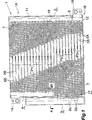
1 zeigt insbesondere die Gesamtstruktur eines Kondensators gemäß der vorliegenden Erfindung; 2 zeigt die Struktur eines Hauptabschnitts von diesem; und 3 zeigt schematisch den Kondensator gemäß der vorliegenden Erfindung. In 3 sind die einzelnen Wärmetauschrohre weggelassen und gewellte Lamellen, Seitenplatten, ein Kühlmitteleinlasselement und ein Kühlmittelauslasselement sind ebenfalls weggelassen. 1 in particular, shows the overall structure of a capacitor according to the present invention; 2 shows the structure of a main section of this; and 3 schematically shows the capacitor according to the present invention. In 3 the individual heat exchange tubes are omitted and corrugated fins, side plates, a coolant inlet element and a coolant outlet element are also omitted.
In den 1 bis 3 umfasst ein Kondensator 1 eine Vielzahl von flachen Wärmetauschrohren 2A, 2B, die aus Aluminium ausgebildet sind, drei Sammeltanks 3, 4, 5, die aus Aluminium ausgebildet sind, gewellte Lamellen 6A, 6B, die aus Aluminium ausgebildet sind, und Seitenplatten 7, die aus Aluminium ausgebildet sind. Die Wärmetauschrohre 2A, 2B sind so angeordnet, dass ihre Breitenrichtung mit einer Richtung von vorne nach hinten zusammenfällt, ihre Längenrichtung mit einer Richtung von links nach rechts zusammenfällt und sie sind voneinander in einer vertikalen Richtung beabstandet. Linke und rechte Endabschnitte der Wärmetauschrohre 2A, 2B sind mittels Löten mit den Sammeltanks 3, 4, 5 verbunden, welche sich in vertikaler Richtung erstrecken. Jede der gewellten Lamellen 6A, 6B ist zwischen benachbarten Wärmetauschrohren 2A, 2B angeordnet und an diese angelötet, oder ist an der äußeren Seite des obersten oder untersten Wärmetauschrohrs 2A, 2B angeordnet und an das entsprechende Wärmetauschrohr 2A, 2B angelötet. Die Seitenplatten 7 sind an den entsprechenden äußeren Seiten der obersten und untersten gewellten Lamellen 6A, 6B angeordnet und sind an diese gewellten Lamellen 6A, 6B gelötet. Zwei oder mehrere Wärmetauschpfade (in der vorliegenden Ausführungsform drei Wärmetauschpfade P1, P2, P3), die jeweils durch eine Vielzahl von Wärmetauschrohren 2A, 2B ausgebildet sind, welche nacheinander in Vertikalrichtung angeordnet sind, sind in einer vertikalen Richtung nebeneinander angeordnet. Auf die drei Wärmetauschpfade wird als die ersten bis dritten Wärmetauschpfade P1, P2, P3 von der oberen Seite Bezug genommen. Die Flussrichtung des Kühlmittels ist innerhalb all dieser Wärmetauschrohre 2A, 2B dieselbe, welche den jeweiligen Wärmetauschpfad P1, P2, P3 ausbilden. Die Flussrichtung des Kühlmittels in den Wärmetauschrohren 2A, 2B, welche einen bestimmten Wärmetauschpfad ausbilden, ist gegenläufig zur Flussrichtung des Kühlmittels in den Wärmetauschrohren 2A, 2B, welche einen anderen Wärmetauschpfad benachbart zu dem bestimmten Wärmetauschpfad ausbilden.In the 1 to 3 includes a capacitor 1 a variety of flat heat exchange tubes 2A . 2 B made of aluminum, three collection tanks 3 . 4 . 5 made of aluminum, corrugated fins 6A . 6B which are formed of aluminum, and side plates 7 which are formed of aluminum. The heat exchange tubes 2A . 2 B are arranged so that their width direction coincides with a front-to-back direction, their length direction coincides with a left-to-right direction, and they are spaced from each other in a vertical direction. Left and right end portions of the heat exchange tubes 2A . 2 B are by means of soldering with the collection tanks 3 . 4 . 5 connected, which extend in the vertical direction. Each of the corrugated fins 6A . 6B is between adjacent heat exchange tubes 2A . 2 B is arranged and soldered to this, or is on the outer side of the top or bottom heat exchange tube 2A . 2 B arranged and to the corresponding heat exchange tube 2A . 2 B soldered. The side plates 7 are on the corresponding outer sides of the top and bottom corrugated fins 6A . 6B arranged and are on these corrugated fins 6A . 6B soldered. Two or more heat exchange paths (three heat exchange paths P1, P2, P3 in the present embodiment) each through a plurality of heat exchange tubes 2A . 2 B are formed, which are arranged one after the other in the vertical direction, are arranged side by side in a vertical direction. The three heat exchange paths are referred to as the first to third heat exchange paths P1, P2, P3 from the upper side. The flow direction of the coolant is within all these heat exchange tubes 2A . 2 B the same, which form the respective heat exchange path P1, P2, P3. The flow direction of the coolant in the heat exchange tubes 2A . 2 B , which form a certain heat exchange path, is opposite to the flow direction of the coolant in the heat exchange tubes 2A . 2 B which form another heat exchange path adjacent to the particular heat exchange path.
Der Kondensator 1 umfasst eine Gruppe G, die aus zumindest zwei Wärmetauschpfaden zusammengestellt ist, welche nacheinander angeordnet sind, und welche den ersten Wärmetauschpfad P1 an dem oberen Ende umfasst (in der vorliegenden Ausführungsform der erste und zweite Wärmetauschpfad P1, P2), und wobei zumindest ein Wärmetauschpfad unter der Gruppe G vorgesehen ist (in der vorliegenden Ausführungsform der dritte Wärmetauschpfad P3). In der Gruppe G fließt Kühlmittel von dem ersten Wärmetauschpfad P1 an dem oberen Ende entgegen dem zweiten Wärmetauschpfad P2 an dem unteren Ende.The capacitor 1 includes a group G composed of at least two heat exchange paths arranged sequentially and including the first heat exchange path P1 at the upper end (in the present embodiment, the first and second heat exchange paths P1, P2), and at least one heat exchange path the group G is provided (in the present embodiment, the third heat exchange path P3). In the group G, coolant flows from the first heat exchange path P1 at the upper end against the second heat exchange path P2 at the lower end.
Ein erster Sammeltank 3 und ein zweiter Sammeltank 4 sind individuell an dem linken Ende des Kondensators 1 vorgesehen. Die Wärmetauschrohre 2A, welche den unteren Endwärmetauschpfad ausbilden, der an der am weitesten flussabwärtigen Seite der Gruppe G in Bezug auf die Kühlmittelflussrichtung angeordnet ist, und der Wärmetauschpfad, der unter der Gruppe G angeordnet ist (in der vorliegenden Ausführungsform der zweite und dritte Wärmetauschpfad P2, P3) sind mit dem ersten Sammeltank 3 mittels Löten verbunden. Die Wärmetauschrohre 2B, welche den oder die übrig gebliebenen Wärmetauschpfad(e) ausbilden (in der vorliegenden Ausführungsform ein erster Wärmetauschpfad P1) sind mit dem zweiten Sammeltank 4 mittels Löten verbunden. Insbesondere ist das untere Ende des ersten Sammeltanks 3 unter dem unteren Ende des zweiten Sammeltanks 4 angeordnet, und die Wärmetauschrohre 2A, welche den zweiten und dritten Wärmetauschpfad P2, P3 ausbilden, sind an einem Abschnitt des ersten Sammeltanks 3 gelötet, der unter dem zweiten Sammeltank 4 angeordnet ist.A first collection tank 3 and a second collection tank 4 are individual to the left end of the capacitor 1 intended. The heat exchange tubes 2A which form the lower end heat exchange path, which is at the most downstream side of the group G with respect to Coolant flow direction is arranged, and the heat exchange path, which is arranged under the group G (in the present embodiment, the second and third heat exchange path P2, P3) are arranged with the first collection tank 3 connected by soldering. The heat exchange tubes 2 B which form the one or more remaining heat exchange path (s) (a first heat exchange path P1 in the present embodiment) are connected to the second header tank 4 connected by soldering. In particular, the lower end of the first collection tank 3 below the lower end of the second collection tank 4 arranged, and the heat exchange tubes 2A which form the second and third heat exchange paths P2, P3 are at a portion of the first header tank 3 soldered under the second collection tank 4 is arranged.
Auf die Wärmetauschrohre 2A, die mit dem ersten Sammeltank 3 verbunden sind, wird als die ersten Wärmetauschrohre Bezug genommen, und auf die Wärmetauschrohre 2B, die mit dem zweiten Sammeltank 4 verbunden sind, wird als die zweiten Wärmetauschrohre Bezug genommen. Auf die gewellten Lamellen 6A, die zwischen den benachbarten ersten Wärmetauschrohren 2A und zwischen dem unteren ersten Endwärmetauschrohr 2A angeordnet ist, und auf die untere Seitenplatte 7 wird als die ersten gewellten Lamellen Bezug genommen, und auf die gewellten Lamellen 6B, die zwischen den benachbarten zweiten Wärmetauschrohren 2B und zwischen dem oberen zweiten Endwärmetauschrohr 2B und der oberen Seitenplatte 7 angeordnet sind, wird als die zweiten gewellten Lamellen Bezug genommen.On the heat exchange tubes 2A that with the first collection tank 3 are referred to as the first heat exchange tubes, and on the heat exchange tubes 2 B that with the second collection tank 4 are referred to as the second heat exchange tubes reference. On the corrugated fins 6A that exist between the adjacent first heat exchange tubes 2A and between the lower first end heat exchange tube 2A is arranged, and on the lower side plate 7 is referred to as the first corrugated fins, and to the corrugated fins 6B between the adjacent second heat exchange tubes 2 B and between the upper second end heat exchange tube 2 B and the upper side plate 7 are arranged, is referred to as the second corrugated fins.
Obwohl der erste Sammeltank 3 und der zweite Sammeltank 4 in Bezug auf ihre Dimensionen entlang der Richtung von vorne nach hinten in etwa gleich sind, ist der erste Sammeltank 3 in Bezug auf den horizontalen Querschnittsbereich größer als der zweite Sammeltank 4. Der erste Sammeltank 3 ist an der linken Seite des zweiten Sammeltanks 4 angeordnet (an der äußeren Seite in Bezug auf eine Richtung von links nach rechts). Die Zentrumslinien des ersten und zweiten Sammeltanks 3, 4 (die Zentren der Sammeltanks 3, 4 in Bezug auf die Richtung von vorne nach hinten) sind an einer gemeinsamen vertikalen Ebene angeordnet, die sich in einer Richtung von links nach rechts erstreckt. Daher haben der erste Sammeltank 3 und der zweite Sammeltank 4 keine Abschnitte, die einander überlappen, wenn sie von einem horizontalen Querschnittsbereich oder von oben angesehen werden. Das obere Ende des ersten Sammeltanks 3 ist über dem oberen Ende des zweiten Sammeltanks 4 angeordnet. Der erste Sammeltank 3 dient als ein Flüssigkeitsempfänger, welcher durch die Verwendung von Gravitationskraft Gas und Flüssigkeit voneinander trennt und die getrennte Flüssigkeit speichert. D. h., dass innere Volumen des ersten Sammeltanks 3 ist so festgelegt, dass ein Abschnitt des gas/flüssig-Mischphasenkühlmittels in den ersten Sammeltank 3 eingeflossen ist. D. h, das flüssig dominierte Mischphasenkühlmittel verbleibt im unteren Bereich innerhalb des ersten Sammeltanks aufgrund der Gravitationskraft, und die Gasphasenkomponente des gas/flüssig-Mischphasenkühlmittels verbleibt aufgrund der Gravitationskraft in einer oberen Region innerhalb des ersten Sammeltanks, wobei nur das flüssig dominierte Mischphasenkühlmittel in die Wärmetauschrohre 2A des dritten Wärmetauschpfads P3 einfließt.Although the first collection tank 3 and the second collection tank 4 In terms of their dimensions along the direction from front to back are about the same, is the first collection tank 3 larger than the second collection tank with respect to the horizontal cross-sectional area 4 , The first collection tank 3 is on the left side of the second collection tank 4 arranged (on the outer side with respect to a direction from left to right). The center lines of the first and second collection tanks 3 . 4 (the centers of the collection tanks 3 . 4 with respect to the front-to-rear direction) are arranged on a common vertical plane extending in a direction from left to right. Therefore, have the first collection tank 3 and the second collection tank 4 no sections that overlap each other when viewed from a horizontal cross-sectional area or from above. The top of the first collection tank 3 is above the top of the second collection tank 4 arranged. The first collection tank 3 serves as a liquid receiver which, by the use of gravitational force, separates gas and liquid and stores the separated liquid. That is, that inner volume of the first collection tank 3 is set so that a portion of the gas / liquid mixed phase refrigerant in the first collection tank 3 has flowed. That is, the liquid-dominated mixed-phase refrigerant remains in the lower portion within the first header tank due to the gravitational force, and the gaseous phase component of the gas-liquid mixed-phase refrigerant remains in an upper region within the first header tank due to gravitational force, with only the liquid dominated mixed-phase refrigerant remaining in the first header tank heat exchange tubes 2A of the third heat exchange path P3.
Der dritte Sammeltank 5 ist an dem rechten Ende des Kondensators 1 angeordnet und alle Wärmetauschrohre 2A, 2B, welche den ersten bis dritten Wärmetauschpfad P1–P3 ausbilden, sind mit dem dritten Sammeltank 5 verbunden. Die Querschnittsgestalt des dritten Sammeltanks 5 ist mit der des zweiten Sammeltanks 4 identisch.The third collection tank 5 is at the right end of the capacitor 1 arranged and all heat exchange tubes 2A . 2 B which form the first to third heat exchange paths P1-P3 are connected to the third collection tank 5 connected. The cross-sectional shape of the third collection tank 5 is with the second collection tank 4 identical.
Das Innere des dritten Sammeltanks 5 ist mittels einer Aluminiumtrennplatte 8, die in einer Höhe zwischen dem zweiten Wärmetauschpfad P2 und dem dritten Wärmetauschpfad P3 vorgesehen ist, in einen oberen Sammelbereich 11 und einen unteren Sammelbereich 12 geteilt. Ein Kühlmitteleinlass 13 ist an einem oberen Endabschnitt des zweiten Sammeltanks 4 ausgebildet und ein Kühlmittelauslass 15 ist an dem unteren Sammelbereich 12 des dritten Sammeltanks 5 ausgebildet. Daher fließt in Gruppe G das Kühlmittel von dem ersten Wärmetauschpfad P1 an dem oberen Ende zum zweiten Wärmetauschpfad P2 an dem unteren Ende, wie oben beschrieben. Ferner ist ein Kühlmitteleinlasselement 14, welches mit dem Kühlmitteleinlass 13 kommuniziert, an den zweiten Sammeltank 4 angeschlossen und ein Kühlmittelauslasselement 16, welches mit dem Kühlmittelauslass 15 kommuniziert, ist an den dritten Sammeltank 5 angeschlossen.The interior of the third collection tank 5 is by means of an aluminum separator 8th , which is provided at a height between the second heat exchange path P2 and the third heat exchange path P3, in an upper collecting area 11 and a lower collection area 12 divided. A coolant inlet 13 is at an upper end portion of the second collection tank 4 formed and a coolant outlet 15 is at the lower collection area 12 of the third collection tank 5 educated. Therefore, in group G, the coolant flows from the first heat exchange path P1 at the upper end to the second heat exchange path P2 at the lower end, as described above. Further, a coolant inlet element 14 , which with the coolant inlet 13 communicates to the second collection tank 4 connected and a coolant outlet 16 , which with the coolant outlet 15 is communicated to the third collection tank 5 connected.
Der zweite Sammeltank 4, ein Abschnitt des ersten Sammeltanks 3, mit dem die ersten Wärmetauschrohre 2A des zweiten Wärmetauschpfads P2 verbunden sind, der obere Sammelbereich 11 des dritten Sammeltanks 5, der erste Wärmetauschpfad P1 und der zweite Wärmetauschpfad P2 bilden einen Kondensationsbereich 1A aus, welcher das Kühlmittel kondensiert. Ein Abschnitt des ersten Sammeltanks 3, mit dem die ersten Wärmetauschrohre 2A des dritten Wärmetauschpfads P3 verbunden sind, der untere Sammelbereich 12 des dritten Sammeltanks 5 und der dritte Wärmetauschpfad P3 bilden einen Unterkühlbereich 1B aus, welcher das Kühlmittel unterkühlt. Der erste und zweite Wärmetauschpfad P1, P2 (alle Wärmetauschpfade der Gruppe G) dienen jeweils als Kühlmittelkondensationspfad für das Kondensieren des Kühlmittels. Der dritte Wärmetauschpfad P3, der unter der Gruppe G angeordnet ist, dient als ein Kühlmittelunterkühlpfad zum Unterkühlen des Kühlmittels.The second collection tank 4 , a section of the first collection tank 3 with which the first heat exchange tubes 2A of the second heat exchange path P2, the upper collecting area 11 of the third collection tank 5 , the first heat exchange path P1 and the second heat exchange path P2 form a condensation region 1A out, which condenses the coolant. A section of the first collection tank 3 with which the first heat exchange tubes 2A of the third heat exchange path P3, the lower collecting area 12 of the third collection tank 5 and the third heat exchange path P3 form a subcooling region 1B off, which undercooled the coolant. The first and second heat exchange paths P1, P2 (all heat exchange paths of the group G) each serve as a refrigerant condensation path for condensing the refrigerant. The third heat exchange path P3, which is located below the group G, serves as a coolant subcooling path for subcooling the coolant.
Alle Wärmetauschrohre 2A, 2B sind gerade und linke Endabschnitte (Endabschnitte an der Seite zum ersten Sammeltank 3) der ersten Wärmetauschrohre 2A, die mit dem ersten Sammeltank 3 verbunden sind, erstrecken sich nach links über die linken Endabschnitte (Endabschnitte an der Seite zum zweiten Sammeltank 4) der zweiten Wärmetauschrohre 2B, die mit dem zweiten Sammeltank 4 verbunden sind. Daher weisen die ersten Wärmetauschrohre 2A an der linken Seite (an der Seite entgegen dem ersten Sammeltank) Vorsprungsabschnitte 2a auf, welche nach links hervorstehen (nach außen in Bezug auf eine Richtung von links nach rechts) über die linken Endabschnitte der zweiten Wärmetauschrohre 2B. Ferner erstrecken sich die linken Endabschnitte der ersten gewellten Lamellen 6A nach links über die linken Endabschnitte der zweiten gewellten Lamellen 6B. Daher weisen die ersten gewellten Lamellen 6A an ihrer linken Seite Vorsprungsabschnitte 6a auf, welche nach links über die linken Endabschnitte der zweiten gewellten Lamellen 6B hervorstehen und sind zwischen den Vorsprungsabschnitten 2a der benachbarten ersten Wärmetauschrohre 2A angeordnet. Daher ist ein Wärmetauschbereich 17 durch die Vorsprungsabschnitte 2a von all den ersten Wärmetauschrohren 2A und den Vorsprungsabschnitten 6a von all den ersten gewellten Lamellen 6A ausgebildet. In 3 ist der Wärmetauschbereich 17 durch Markierungen angezeigt. All heat exchange tubes 2A . 2 B are straight and left end portions (end portions on the side to the first collection tank 3 ) of the first heat exchange tubes 2A that with the first collection tank 3 are connected, extend to the left via the left end portions (end portions on the side to the second collection tank 4 ) of the second heat exchange tubes 2 B that with the second collection tank 4 are connected. Therefore, the first heat exchange tubes 2A on the left side (on the side opposite to the first collection tank) projecting portions 2a which project to the left (outward with respect to a left-to-right direction) via the left end portions of the second heat exchange tubes 2 B , Further, the left end portions of the first corrugated fins extend 6A to the left over the left end portions of the second corrugated fins 6B , Therefore, the first corrugated fins show 6A on its left side projecting portions 6a on which left over the left end portions of the second corrugated fins 6B protrude and are between the protrusion sections 2a the adjacent first heat exchange tubes 2A arranged. Therefore, a heat exchange area 17 through the protrusion sections 2a from all the first heat exchange tubes 2A and the protrusion portions 6a of all the first corrugated fins 6A educated. In 3 is the heat exchange area 17 indicated by markers.
Ein Zwischenelement 18, das aus Aluminium ausgebildet ist, ist zwischen dem ersten oberen Endwärmetauschrohr 2A des zweiten Wärmetauschpfads P2 und dem unteren zweiten Endwärmetauschrohr 2B des ersten Wärmetauschpfads P1 so angeordnet, dass das Zwischenelement 18 von diesen Wärmetauschrohren 2A, 2B getrennt ist und im Wesentlichen parallel zu den Wärmetauschrohren 2A, 2B wird. Eine erste gewellte Lamelle 6A ist zwischen dem oberen ersten Endwärmetauschrohr 2A des zweiten Wärmetauschpfads P2 und dem Zwischenelement 18 angeordnet und ist an das erste Wärmetauschrohr 2A und das Zwischenelement 18 angelötet. Eine zweite gewellte Lamelle 6B ist zwischen dem zweiten unteren Endwärmetauschrohr 2B des ersten Wärmetauschpfads P1 und dem Zwischenelement 18 angeordnet und ist an das zweite Wärmetauschrohr 2B und das Zwischenelement 18 angelötet. Ein Rohr, das komplett identisch mit dem zweiten Wärmetauschrohr 2B ist, wird als das Zwischenelement 18 verwendet. Da gegenüberliegende Endabschnitte des Zwischenelements 18 nicht in den ersten Sammeltank 3 und den dritten Sammeltank 5 eingesetzt sind, wird die Verwendung eines Rohrs möglich, das komplett identisch mit dem zweiten Wärmetauschrohr 2B ist.An intermediate element 18 formed of aluminum is between the first upper end heat exchange tube 2A the second heat exchange path P2 and the lower second end heat exchange pipe 2 B of the first heat exchange path P1 so arranged that the intermediate element 18 from these heat exchange tubes 2A . 2 B is separated and substantially parallel to the heat exchange tubes 2A . 2 B becomes. A first corrugated lamella 6A is between the upper first end heat exchange tube 2A the second heat exchange path P2 and the intermediate element 18 arranged and is to the first heat exchange tube 2A and the intermediate element 18 soldered. A second wavy lamella 6B is between the second lower end heat exchange tube 2 B the first heat exchange path P1 and the intermediate element 18 arranged and is to the second heat exchange tube 2 B and the intermediate element 18 soldered. A tube that is completely identical to the second heat exchange tube 2 B is, is called the intermediate element 18 used. Because opposite end portions of the intermediate element 18 not in the first collection tank 3 and the third collection tank 5 are used, the use of a tube is possible, which is completely identical to the second heat exchange tube 2 B is.
Der Kondensator 1 ist durch Chargenlöten (batch brazing) von allen Komponenten hergestellt.The capacitor 1 is produced by batch brazing of all components.
Der Kondensator 1 baut einen Kühlmittelzyklus in Kooperation mit einem Kompressor, einem Expansionsventil (Druckminderer) und einem Verdampfer auf; und der Kühlmittelzyklus ist an einem Fahrzeug als eine Fahrzeugklimaanlage montiert.The capacitor 1 builds a coolant cycle in cooperation with a compressor, an expansion valve (pressure reducer) and an evaporator; and the refrigerant cycle is mounted on a vehicle as a vehicle air conditioner.
In dem Kondensator 1, der die oben beschriebene Struktur aufweist, fließt ein Gasphasenkühlmittel mit einer hohen Temperatur und hohem Druck, der durch den Kompressor erzeugt wurde, über das Kühlmitteleinlasselement 14 und den Kühlmitteleinlass 13 in den zweiten Sammeltank 4. Das Gasphasenkühlmittel wird kondensiert während es innerhalb der zweiten Wärmetauschrohre 2B des ersten Wärmetauschpfads P1 nach rechts fließt, und fließt in den oberen Sammelbereich 11 des dritten Sammeltanks 5. Das Kühlmittel, das in den oberen Sammelbereich 11 des dritten Sammeltanks 5 geflossen ist, wird kondensiert während es innerhalb der ersten Wärmetauschrohre 2A des zweiten Wärmetauschpfades P2 nach links fließt, und fließt in den ersten Sammeltank 3.In the condenser 1 having the above-described structure, a high-temperature and high-pressure gas-phase refrigerant generated by the compressor flows via the refrigerant inlet member 14 and the coolant inlet 13 in the second collection tank 4 , The gas phase refrigerant is condensed while inside the second heat exchange tubes 2 B of the first heat exchange path P1 flows to the right, and flows into the upper collecting area 11 of the third collection tank 5 , The coolant entering the upper collection area 11 of the third collection tank 5 is flowed while it is condensed within the first heat exchange tubes 2A of the second heat exchange path P2 flows to the left, and flows into the first collection tank 3 ,
Das Kühlmittel, das in den ersten Sammeltank 3 geflossen ist, ist gas/flüssig-Mischphasenkühlmittel. Ein Abschnitt des gas/flüssig-Mischphasenkühlmittels, d. h. Flüssigkeitsdominiertes Mischphasenkühlmittel, verbleibt aufgrund der Gravitationskraft in einem unteren Bereich innerhalb des ersten Sammeltanks 3 und tritt in die ersten Wärmetauschrohre 2A des dritten Wärmetauschpfads P3 ein. Das Flüssigkeitsdominierte Mischphasenkühlmittel, das in die ersten Wärmetauschrohre 2A des dritten Wärmetauschpfads P3 eingetreten ist, wird unterkühlt, während es innerhalb der ersten Wärmetauschrohre 2A nach rechts fließt. Danach tritt das unterkühlte Kühlmittel in den unteren Sammelbereich 12 des dritten Sammeltanks 5 ein, und fließt über den Kühlmittelauslass 15 und das Kühlmittelauslasselement 16 aus. Das Kühlmittel wird dann über ein Ausdehnungsventil in den Verdampfer geführt.The coolant that is in the first collection tank 3 is gas / liquid mixed-phase refrigerant. A portion of the gas / liquid mixed phase refrigerant, ie, liquid dominated mixed phase refrigerant, remains in a lower region within the first header tank due to gravitational force 3 and enters the first heat exchange tubes 2A of the third heat exchange path P3. The liquid-dominated mixed-phase refrigerant entering the first heat exchange tubes 2A of the third heat exchange path P3 is supercooled while inside the first heat exchange tubes 2A flows to the right. Thereafter, the supercooled coolant enters the lower collection area 12 of the third collection tank 5 and flows over the coolant outlet 15 and the coolant outlet member 16 out. The coolant is then passed through an expansion valve in the evaporator.
Während dessen verbleibt die Gasphasenkomponente des gas/flüssig-Mischphasenkühlmittels, das in den ersten Sammeltank 3 geflossen ist, in einem oberen Bereich innerhalb des ersten Sammeltanks 3.During this, the gas phase component of the gas / liquid mixed phase refrigerant remaining in the first collection tank remains 3 flowed into an upper area within the first collection tank 3 ,
4 bis 14 zeigen andere Ausführungsformen des Kondensators gemäß der vorliegenden Erfindung. In den 4 bis 6 und 9 bis 14, welche schematisch den Kondensator zeigen, wurden die einzelnen Wärmetauschrohre weggelassen und die gewellten Lamellen, die Seitenplatten, das Kühlmitteleinlasselement und das Kühlmittelauslasselement wurden ebenfalls weggelassen. 4 to 14 show other embodiments of the capacitor according to the present invention. In the 4 to 6 and 9 to 14 schematically showing the condenser, the individual heat exchange tubes have been omitted, and the corrugated fins, the side plates, the refrigerant inlet member and the refrigerant outlet member have also been omitted.
Im Fall eines Kondensators 20, der in 4 gezeigt ist, sind vier Wärmetauschpfade P1, P2, P3, P4, die jeweils durch eine Vielzahl von Wärmetauschrohren 2A, 2B ausgebildet sind, die nacheinander in Vertikalrichtung angeordnet sind, in Vertikalrichtung nebeneinander angeordnet. Auf die vier Wärmetauschpfade wird als die ersten bis vierten Wärmetauschpfade P1, P2, P3, P4 von der oberen Seite aus Bezug genommen. Die Flussrichtung des Kühlmittels ist dieselbe innerhalb all den Wärmetauschrohren 2A, 2B, welche den jeweiligen Wärmetauschpfad P1, P2, P3, P4 ausbilden. Die Flussrichtung des Kühlmittels in den Wärmetauschrohren 2A, 2B, welche einen bestimmten Wärmetauschpfad ausbilden, ist gegenteilig zu der Flussrichtung des Kühlmittels in den Wärmetauschrohren 2A, 2B, welche einen anderen Wärmetauschpfad benachbart zu dem bestimmten Wärmetauschpfad ausbilden.In the case of a capacitor 20 who in 4 are shown, four heat exchange paths P1, P2, P3, P4, each by a plurality of Heat exchange tubes 2A . 2 B are formed, which are arranged one after the other in the vertical direction, arranged side by side in the vertical direction. The four heat exchange paths are referred to as the first through fourth heat exchange paths P1, P2, P3, P4 from the upper side. The flow direction of the coolant is the same within all the heat exchange tubes 2A . 2 B which form the respective heat exchange path P1, P2, P3, P4. The flow direction of the coolant in the heat exchange tubes 2A . 2 B which form a certain heat exchange path is opposite to the flow direction of the refrigerant in the heat exchange tubes 2A . 2 B which form another heat exchange path adjacent to the particular heat exchange path.
Der Kondensator 20 umfasst eine Gruppe G, die aus zumindest zwei Wärmetauschpfaden zusammengestellt ist, welche nacheinander angeordnet sind und welche den ersten Wärmetauschpfad P1 an dem oberen Ende (in der vorliegenden Ausführungsform die ersten bis dritten Wärmetauschpfade P1, P2, P3) umfassen, und zumindest ein Wärmetauschpfad (in der vorliegenden Ausführungsform der vierte Wärmetauschpfad P4) ist unter der Gruppe G vorgesehen. In der Gruppe G fließt das Kühlmittel von dem ersten Wärmetauschpfad P1 von dem oberen Ende zum dritten Wärmetauschpfad P3 an dem unteren Ende.The capacitor 20 includes a group G composed of at least two heat exchange paths arranged one after another and including the first heat exchange path P1 at the upper end (in the present embodiment, the first to third heat exchange paths P1, P2, P3), and at least one heat exchange path (FIG. in the present embodiment, the fourth heat exchange path P4) is provided under the group G. In the group G, the coolant flows from the first heat exchange path P1 from the upper end to the third heat exchange path P3 at the lower end.
Linke und rechte Endabschnitte der Wärmetauschrohre 2A, welche den unteren Endwärmetauschpfad ausbilden, der an der am weitesten flussabwärtigen Seite der Gruppe G in Bezug auf die Kühlmittelflussrichtung angeordnet ist, und der Wärmetauschpfad, der unter der Gruppe G angeordnet ist (in der vorliegenden Ausführungsform der dritte und vierte Wärmetauschpfad P3, P4) sind jeweils mit dem ersten Sammeltank 3 und dem dritten Sammeltank 5 mittels Löten verbunden. Die linken und rechten Endabschnitte der Wärmetauschrohre 2B, welche alle die verbleibenden Wärmetauschpfade ausbilden (in der vorliegenden Ausführungsform der erste und zweite Wärmetauschpfad P1, P2) sind jeweils mit dem zweiten Sammeltank 4 und dem dritten Sammeltank 5 mittels Löten verbunden. Daher sind die Wärmetauschrohre 2A, welche die dritten und vierten Wärmetauschpfade P3, P4 ausbilden, die ersten Wärmetauschrohre, und die Wärmetauschrohre 2B, welche die ersten und zweiten Wärmetauschpfade P1, P2 ausbilden, sind die zweiten Wärmetauschrohre.Left and right end portions of the heat exchange tubes 2A which form the lower end heat exchange path located at the most downstream side of the group G with respect to the refrigerant flow direction, and the heat exchange path located below the group G (in the present embodiment, the third and fourth heat exchange paths P3, P4) are each with the first collection tank 3 and the third collection tank 5 connected by soldering. The left and right end portions of the heat exchange tubes 2 B , which all form the remaining heat exchange paths (in the present embodiment, the first and second heat exchange paths P1, P2) are respectively connected to the second collection tank 4 and the third collection tank 5 connected by soldering. Therefore, the heat exchange tubes 2A which form the third and fourth heat exchange paths P3, P4, the first heat exchange tubes, and the heat exchange tubes 2 B which form the first and second heat exchange paths P1, P2 are the second heat exchange tubes.
Das Innere des dritten Sammeltanks 5 ist in einen oberen Sammelbereich 23, einen mittleren Sammelbereich 24 und einen unteren Sammelbereich 25 durch Aluminiumtrennplatten 21 und 22 geteilt, welche jeweils in einer Höhe zwischen dem ersten Wärmetauschpfad P1 und dem zweiten Wärmetauschpfad P2 und eine Höhe zwischen dem dritten Wärmetauschpfad P3 und dem vierten Wärmetauschpfad P4 vorgesehen sind. Ein Kühlmitteleinlass 26 ist an dem oberen Sammelbereich 23 des dritten Sammeltanks 5 ausgebildet und ein Kühlmittelauslass 27 ist an dem unteren Sammelbereich 25 des dritten Sammeltanks 5 ausgebildet. Linke Endabschnitte der linken Wärmetauschrohre 2B des ersten Wärmetauschpfads P1 sind mit dem zweiten Sammeltank 4 verbunden und rechte Endabschnitte von diesem sind mit dem oberen Sammelbereich 23 des dritten Sammeltanks 5 verbunden. Linke Endabschnitte der zweiten Wärmetauschrohre 2B des zweiten Wärmetauschpfads P2 sind mit dem zweiten Sammeltank 4 verbunden und deren rechte Endabschnitte sind mit dem Zwischensammelbereich 24 des dritten Sammeltanks 5 verbunden. Linke Endabschnitte der ersten Wärmetauschrohre 2A des dritten Wärmetauschpfads P3 sind mit dem ersten Sammeltank 3 verbunden und deren rechte Endabschnitte sind mit dem Zwischensammelbereich 24 des dritten Sammeltanks 5 verbunden. Linke Endabschnitte der ersten Wärmerauscherrohre 2A des vierten Wärmetauschpfads P4 sind mit dem ersten Sammeltank 3 verbunden und deren rechte Endabschnitte sind mit dem unteren Sammelbereich 25 des dritten Sammeltanks 5 verbunden. Als Ergebnis fließt in Gruppe G das Kühlmittel von dem ersten Wärmetauschpfad P1 an dem oberen Ende zum dritten Wärmetauschpfad P3 an dem unteren Ende, wie oben beschrieben. Insbesondere sind ein Einlasselement (nicht gezeigt), welches mit dem Kühlmitteleinlass 26 kommuniziert, und ein Kühlmittelauslasselement (nicht gezeigt), welches mit dem Kühlmittelauslass 27 kommuniziert, an den dritten Sammeltank 5 gefügt.The interior of the third collection tank 5 is in an upper collection area 23 , a middle collection area 24 and a lower collection area 25 through aluminum partitions 21 and 22 which are respectively provided at a height between the first heat exchange path P1 and the second heat exchange path P2 and a height between the third heat exchange path P3 and the fourth heat exchange path P4. A coolant inlet 26 is at the upper collection area 23 of the third collection tank 5 formed and a coolant outlet 27 is at the lower collection area 25 of the third collection tank 5 educated. Left end portions of the left heat exchange tubes 2 B of the first heat exchange path P1 are with the second collection tank 4 connected and right end portions of this are with the upper collection area 23 of the third collection tank 5 connected. Left end portions of the second heat exchange tubes 2 B of the second heat exchange path P2 are connected to the second collection tank 4 connected and their right end portions are with the intermediate collection area 24 of the third collection tank 5 connected. Left end portions of the first heat exchange tubes 2A of the third heat exchange path P3 are connected to the first collection tank 3 connected and their right end portions are with the intermediate collection area 24 of the third collection tank 5 connected. Left end sections of the first heat exchanger tubes 2A of the fourth heat exchange path P4 are connected to the first collection tank 3 connected and their right end portions are connected to the lower collection area 25 of the third collection tank 5 connected. As a result, in group G, the coolant flows from the first heat exchange path P1 at the upper end to the third heat exchange path P3 at the lower end, as described above. In particular, an inlet member (not shown) connected to the coolant inlet 26 communicates, and a coolant outlet member (not shown) connected to the coolant outlet 27 communicates to the third collection tank 5 together.
Der zweite Sammeltank 4, ein Abschnitt des ersten Sammeltanks 3, mit welchem die ersten Wärmetauschrohre 2A des dritten Wärmetauschpfads P3 verbunden sind, der obere Sammelbereich 23 und der Zwischensammelbereich 24 des dritten Sammeltanks 5 und die ersten bis dritten Wärmetauschpfade P1 bis P3 bilden einen Kondensationsbereich 20A aus, welcher das Kühlmittel kondensiert. Ein Abschnitt des ersten Sammeltanks 3, mit welchem die ersten Wärmetauschrohre 2A des vierten Wärmetauschpfads P4 verbunden sind, der untere Sammelbereich 25 des dritten Sammeltanks 5 und der vierte Wärmetauschpfad P4 bilden einen Unterkühlbereich 20B aus, welcher das Kühlmittel unterkühlt. Die ersten bis dritten Wärmetauschpfade P1–P3, welche alle die Wärmetauschpfade der Gruppe G sind, dienen jeder als ein Kühlmittelkondensationspfad zum Kondensieren des Kühlmittels, und der vierte Wärmetauschpfad P4, der unter der Gruppe G angeordnet ist, dient als ein Kühlmittelunterkühlpfad zum Unterkühlen des Kühlmittels.The second collection tank 4 , a section of the first collection tank 3 , with which the first heat exchange tubes 2A of the third heat exchange path P3, the upper collecting area 23 and the intermediate collection area 24 of the third collection tank 5 and the first to third heat exchange paths P1 to P3 form a condensation region 20A out, which condenses the coolant. A section of the first collection tank 3 , with which the first heat exchange tubes 2A of the fourth heat exchange path P4, the lower collecting area 25 of the third collection tank 5 and the fourth heat exchange path P4 form a subcooling region 20B off, which undercooled the coolant. The first to third heat exchange paths P1-P3, which are all the heat exchange paths of the group G, each serve as a refrigerant condensation path for condensing the refrigerant, and the fourth heat exchange path P4 located below the group G serves as a refrigerant subcooling path for supercooling the refrigerant ,
Obwohl nicht dargestellt, ist in dem Kondensator 20, der in 4 gezeigt ist, ein Zwischenelement 18, das aus Aluminium ausgebildet ist, zwischen dem ersten oberen Endwärmetauschrohr 2A des dritten Wärmetauschpfads P3 und dem unteren zweiten Endwärmetauschrohr 2B des zweiten Wärmetauschpfads P2 so angeordnet, dass das Zwischenelement 18 von diesen Wärmetauschrohren 2A, 2B getrennt ist und im Wesentlichen parallel zu den Wärmetauschrohren 2A, 2B wird. Eine erste gewellte Lamelle 6A ist zwischen dem oberen ersten Endwärmetauschrohr 2A es dritten Wärmetauschpfads P3 und dem Zwischenelement 18 angeordnet und ist an das erste Wärmetauschrohr 2A und das Zwischenelement 18 gelötet. Eine zweite gewellte Lamelle 6B ist zwischen dem unteren zweiten Endwärmetauschrohr 2B des zweiten Wärmetauschpfads P2 und dem Zwischenelement 18 angeordnet und ist an das zweite Wärmetauschrohr 2B und das Zwischenelement 18 gelötet.Although not shown, is in the capacitor 20 who in 4 shown is an intermediate element 18 formed of aluminum, between the first upper end heat exchange tube 2A the third heat exchange path P3 and the lower second end heat exchange pipe 2 B of the second heat exchange path P2 so arranged that the intermediate element 18 from these heat exchange tubes 2A . 2 B is separated and substantially parallel to the heat exchange tubes 2A . 2 B becomes. A first corrugated lamella 6A is between the upper first end heat exchange tube 2A it third heat exchange path P3 and the intermediate element 18 arranged and is to the first heat exchange tube 2A and the intermediate element 18 soldered. A second wavy lamella 6B is between the lower second end heat exchange tube 2 B the second heat exchange path P2 and the intermediate element 18 arranged and is to the second heat exchange tube 2 B and the intermediate element 18 soldered.
Die verbleibende Struktur ist ähnlich der des Kondensators, der in 1 bis 3 gezeigt ist.The remaining structure is similar to that of the capacitor used in 1 to 3 is shown.
In dem Kondensator 20, der in 4 gezeigt ist, fließt Gasphasenkühlmittel mit einer hohen Temperatur und hohem Druck, der durch den Kompressor erzeugt wird, in den oberen Sammelbereich 23 des dritten Sammeltanks 5 über das Kühlmitteleinlasselement und den Kühlmitteleinlass 26. Das Gasphasenkühlmittel ist kondensiert, während es nach links innerhalb der zweiten Wärmetauschrohre 2B des ersten Wärmetauschpfads P1 fließt und fließt dann in den zweiten Sammeltank 4. Das Kühlmittel, das in den zweiten Sammeltank 4 geflossen ist, wird während es nach rechts innerhalb der zweiten Wärmetauschrohre 2B des zweiten Wärmetauschpfads P2 fließt, kondensiert, und fließt dann in den Zwischensammelbereich 24 des dritten Sammeltanks 5. Das Kühlmittel, das in den Zwischensammelbereich 24 des dritten Sammeltanks 5 fließt, wird während es nach links innerhalb der ersten Wärmetauschrohre 2A des dritten Wärmetauschpfads P3 fließt, kondensiert, und fließt dann in den ersten Sammeltank 3.In the condenser 20 who in 4 is shown, gas phase refrigerant flows at a high temperature and high pressure, which is generated by the compressor, in the upper collecting area 23 of the third collection tank 5 via the coolant inlet element and the coolant inlet 26 , The gas phase refrigerant is condensed while moving to the left within the second heat exchange tubes 2 B of the first heat exchange path P1 flows and then flows into the second collection tank 4 , The coolant that is in the second collection tank 4 is flowed while it is right inside the second heat exchange tubes 2 B of the second heat exchange path P2 flows, condenses, and then flows into the intermediate collecting area 24 of the third collection tank 5 , The coolant entering the intermediate collection area 24 of the third collection tank 5 flows while being left inside the first heat exchange tubes 2A of the third heat exchange path P3 flows, condenses, and then flows into the first collection tank 3 ,
Das Kühlmittel, das in den ersten Sammeltank 3 geflossen ist, ist ein gas/flüssig-Mischphasenkühlmittel. Ein Abschnitt des gas/flüssig-Mischphasenkühlmittels, d. h. Flüssigkeitsdominiertes Mischphasenkühlmittel, verbleibt aufgrund der Gravitationskraft in einem unteren Bereich innerhalb des ersten Sammeltanks 3 und tritt in die ersten Wärmetauschrohre 2A des vierten Wärmetauschpfads P4 ein. Das Flüssigkeitsdominierte Mischphasenkühlmittel, das in die ersten Wärmetauschrohre 2A des vierten Wärmetauschpfads P4 eingetreten ist, wird, während es nach rechts innerhalb der ersten Wärmetauschrohre 2A fließt, unterkühlt. Danach tritt das unterkühlte Kühlmittel in den unteren Sammelbereich 25 des dritten Sammeltanks 5 ein und fließt über den Kühlmittelauslass 27 und das Kühlmittelauslasselement aus. Das Kühlmittel wird dann über ein Expansionsventil in den Verdampfer geführt.The coolant that is in the first collection tank 3 is a gas / liquid mixed-phase refrigerant. A portion of the gas / liquid mixed phase refrigerant, ie, liquid dominated mixed phase refrigerant, remains in a lower region within the first header tank due to gravitational force 3 and enters the first heat exchange tubes 2A of the fourth heat exchange path P4. The liquid-dominated mixed-phase refrigerant entering the first heat exchange tubes 2A of the fourth heat exchange path P4 is, while it is to the right within the first heat exchange tubes 2A flows, undercooled. Thereafter, the supercooled coolant enters the lower collection area 25 of the third collection tank 5 and flows over the coolant outlet 27 and the coolant outlet member. The coolant is then passed through an expansion valve in the evaporator.
Inzwischen verbleibt die Gasphasenkomponente des gas/flüsig-Mischphasenkühlmittels, das in den ersten Sammeltank 3 geflossen ist, in einem oberen Bereich innerhalb des ersten Sammeltanks 3.Meanwhile, the gas phase component of the gas / liquid mixed-phase refrigerant remaining in the first collection tank remains 3 flowed into an upper area within the first collection tank 3 ,
Im Fall eines Kondensators 30, der in 5 gezeigt ist, ist der erste Sammeltank 3 aus einem rohrförmigen Hauptkörper 31 zusammengestellt, der aus Aluminium ausgebildet ist und der ein offenes, oberes Ende und ein geschlossenes, unteres Ende aufweist; und aus einem Deckel 32, welcher entfernbar an dem oberen Ende des rohrförmigen Hauptkörpers 31 so angebracht ist, dass er die obere Endöffnung des rohrförmigen Hauptkörpers 31 verschließt. Wenn der Kondensator 30 hergestellt wird, wird nur der rohrförmige Hauptkörper 31 einem Chargenlöten gleichzeitig mit anderen Elementen ausgesetzt. Nach der Herstellung des Kondensators 30 wird der Deckel 32 an dem rohrförmigen Hauptkörper 31 angebracht.In the case of a capacitor 30 who in 5 shown is the first collection tank 3 from a tubular main body 31 Assembled, which is formed of aluminum and having an open, upper end and a closed, lower end; and from a lid 32 which is removably attached to the upper end of the tubular main body 31 is attached so as to be the upper end opening of the tubular main body 31 closes. When the capacitor 30 is made only the tubular main body 31 subjected to batch brazing simultaneously with other elements. After the production of the capacitor 30 becomes the lid 32 on the tubular main body 31 appropriate.
Ferner ist ein Trockenmittel 33 in dem ersten Sammeltank 3 angeordnet. Das Trockenmittel 33 entfernt die Feuchtigkeit von dem Kühlmittel, das in dem ersten Sammeltank 3 über die ersten Wärmetauschrohre 2A des dritten Wärmetauschpfades P3 einfließt. Das Trockenmittel 33 ist in dem rohrförmigen Hauptkörper 31 nach der Herstellung des Kondensators 30, aber vor dem Anbringen des Deckels 32 an dem rohrförmigen Hauptkörper 31 platziert.Further, a desiccant 33 in the first collection tank 3 arranged. The desiccant 33 removes the moisture from the coolant that is in the first collection tank 3 over the first heat exchange tubes 2A the third heat exchange path P3 flows. The desiccant 33 is in the tubular main body 31 after the production of the capacitor 30 but before attaching the lid 32 on the tubular main body 31 placed.
Die verbleibende Struktur ist gleich derjenigen des Kondensators 20, der in 4 gezeigt ist, und Kühlmittel fließt in derselben Weise wie im Fall des Kondensators 20, der in 4 gezeigt ist. Insbesondere wird in 5 ein Kondensationsbereich, der eine Konfiguration ähnlich derjenigen aufweist, die der Kondensator 20 hat, der in 4 gezeigt ist, mit 30A bezeichnet und ein Unterkühlbereich, der eine Konfiguration aufweist, die ähnlich derjenigen des Kondensators 20 ist, der in 4 gezeigt ist, wird mit 30B bezeichnet.The remaining structure is equal to that of the capacitor 20 who in 4 and coolant flows in the same manner as in the case of the condenser 20 who in 4 is shown. In particular, in 5 a condensation region having a configuration similar to that of the capacitor 20 has that in 4 shown with 30A and a sub-cooling region having a configuration similar to that of the capacitor 20 is that in 4 shown is with 30B designated.
Im Fall eines Kondensators 35, der in den 6 und 7 gezeigt ist, ist ein gas/flüssig-Trennelement 36, das aus Aluminium ausgebildet ist, innerhalb des ersten Sammeltanks 3 an einer Höhe zwischen dem dritten Wärmetauschpfad P3 und dem vierten Wärmetauschpfad P4 angeordnet. Das gas/flüssig-Trennelement 36 nimmt eine plattenähnliche Gestalt an und weist ein gleichgerichtetes Durchgangsloch 37 auf, das in dieses ausgebildet ist. Das gas/flüssig-Trennelement 36 verhindert den Einfluss von aufgerührten Wirbeln, die durch den Fluss des Kühlmittels erzeugt werden, das von den ersten Wärmetauschrohren 2A des dritten Wärmetauschpfads P3 in den ersten Sammeltank 3 fließt, so dass sie sich nicht in einen Abschnitt des Inneren des ersten Sammeltanks 3 fortsetzen, der unter dem gas/flüssig-Trennelement 36 angeordnet ist, um dabei die Gasphasenkomponente des gas/flüssig-Mischphasenkühlmittels dazu zu bringen, in dem oberen Bereich des Inneren des ersten Sammeltanks 3 zu verbleiben. Als Ergebnis wird nur das flüssig-dominierte Mischphasenkühlmittel in den Abschnitt des Inneren des ersten Sammeltanks 3 zugeführt, der unter dem gas/flüssig-Trennelement 36 angeordnet ist, mittels des gleichgerichteten Durchgangsloches 37, wobei das flüssig-dominierte Mischphasenkühlmittel effektiv in die ersten Wärmetauschrohre 2A des vierten Wärmetauschpfads P4 einfließt.In the case of a capacitor 35 in the 6 and 7 is shown is a gas / liquid separator 36 formed of aluminum, within the first collection tank 3 is disposed at a height between the third heat exchange path P3 and the fourth heat exchange path P4. The gas / liquid separator 36 assumes a plate-like shape and has a rectified through hole 37 trained in this. The gas / liquid separator 36 prevents the influence of agitated swirls generated by the flow of coolant from the first heat exchange tubes 2A of the third heat exchange path P3 in the first collection tank 3 flows so that they do not get into a section of the interior of the first collection tank 3 continue under the gas / liquid separator 36 while the gas phase component of the gas / liquid Mixed phase refrigerant to bring in the upper region of the interior of the first collection tank 3 to remain. As a result, only the liquid-dominated mixed-phase refrigerant enters the section of the interior of the first header tank 3 fed under the gas / liquid separator 36 is arranged, by means of the rectified through hole 37 wherein the liquid dominated mixed phase refrigerant effectively into the first heat exchange tubes 2A the fourth heat exchange path P4 flows.
Insbesondere kann ein Trockenmittel 33 in einem Abschnitt des ersten Sammeltanks 3 über dem gas/flüssig-Trennelement 36 angeordnet sein. In diesem Fall, ähnlich im Fall des Kondensators 30, der in 5 gezeigt ist, ist der erste Sammeltank 3 aus einem rohrförmigen Hauptkörper 31 zusammengestellt, der aus Aluminium ausgebildet ist und der ein offenes oberes Ende und ein geschlossenes unteres Ende aufweist; und aus einem Deckel 32, der entfernbar an dem oberen Ende des rohrförmigen Hauptkörpers 31 so angebracht ist, dass die obere Endöffnung des rohrförmigen Hauptkörpers 31 schließt. Wenn der Kondensator 30 hergestellt wird, wird nur der rohrförmige Hauptkörper 31 gleichzeitig mit anderen Elementen einem Chargenlöten unterzogen. Der Deckel 32 wird an den rohrförmigen Hauptkörper 31 angebracht, nachdem das Trockenmittel 33 in den rohrförmigen Hauptkörper 31 platziert wird, nach der Herstellung des Kondensators 30.In particular, a desiccant 33 in a section of the first collection tank 3 above the gas / liquid separator 36 be arranged. In this case, similar in the case of the capacitor 30 who in 5 shown is the first collection tank 3 from a tubular main body 31 Assembled, which is formed of aluminum and having an open upper end and a closed lower end; and from a lid 32 Removable at the upper end of the tubular main body 31 is attached so that the upper end opening of the tubular main body 31 closes. When the capacitor 30 is made only the tubular main body 31 batch-brazed simultaneously with other elements. The lid 32 is attached to the tubular main body 31 attached after the desiccant 33 in the tubular main body 31 is placed after the manufacture of the capacitor 30 ,
Die verbleibende Struktur ist gleich derjenigen des Kondensators 20, der in 4 gezeigt ist, und das Kühlmittel fließt in derselben Weise, wie im Fall des Kondensators 20, der in 4 gezeigt ist. Insbesondere wird ein Kondensationsbereich in 6 und 7, der eine Konfiguration gleich derjenigen des Kondensators 20 aufweist, der in 4 gezeigt ist, mit 35A bezeichnet, und ein Unterkühlbereich, der eine Konfiguration gleich derjenigen des Kondensators 20 aufweist, der in 4 gezeigt ist, ist mit 35B bezeichnet.The remaining structure is equal to that of the capacitor 20 who in 4 is shown, and the refrigerant flows in the same manner as in the case of the condenser 20 who in 4 is shown. In particular, a condensation area in 6 and 7 which has a configuration equal to that of the capacitor 20 which has in 4 shown with 35A and a subcooling region having a configuration equal to that of the capacitor 20 which has in 4 is shown is with 35B designated.
Im Kondensator 35, der in den 6 und 7 gezeigt ist, kann statt dem gas/flüssig-Trennelement 36 ein Filter 40, wie in 8 gezeigt, innerhalb des ersten Sammeltanks 3 in einer Höhe zwischen dem dritten Wärmetauschpfad P3 und dem vierten Wärmetauschpfad P4 angeordnet sein. Der Filter 40 ist aus einem plattenähnlichen Aluminiumkörper 41 aufgebaut, der ein Durchgangsloch 42 aufweist, und ein Edelstahlgitter 43 ist an dem Körper 41 befestigt, so dass es das Durchgangsloch 42 abdeckt. In diesem Fall können Fremdkörper, die im Kühlmittel enthalten sind, entfernt werden.In the condenser 35 in the 6 and 7 can be shown, instead of the gas / liquid separator 36 a filter 40 , as in 8th shown inside the first collection tank 3 be arranged at a height between the third heat exchange path P3 and the fourth heat exchange path P4. The filter 40 is made of a plate-like aluminum body 41 built, which is a through hole 42 and a stainless steel grid 43 is on the body 41 attached, making it the through hole 42 covers. In this case, foreign matter contained in the coolant can be removed.
Im Fall des Kondensators 50, der in 9 gezeigt ist, sind vier Wärmetauschpfade P1, P2, P3, P4, die jeweils durch eine Vielzahl von Wärmetauschrohren 2A, 2B ausgebildet sind, die nacheinander in Vertikalrichtung angeordnet sind, in Vertikalrichtung nebeneinander angeordnet. Auf die vier Wärmetauschpfade wird als die ersten bis vierten Wärmetauschpfade P1, P2, P3, P4 von der oberen Seite aus Bezug genommen. Die Flussrichtung des Kühlmittels ist innerhalb all der Wärmetauschrohre 2A, 2B, welche die jeweiligen Wärmetauschpfade P1, P2, P3, P4 ausbilden, dieselbe. Die Flussrichtung des Kühlmittels in den Wärmetauschrohren 2A, 2B, welche einen bestimmten Wärmetauschpfad ausbilden, ist gegenläufig zur Flussrichtung des Kühlmittels in den Wärmetauschrohren 2A, 2B, welche die anderen Wärmetauschpfade benachbart zu dem bestimmten Wärmetauschpfad ausbilden.In the case of the capacitor 50 who in 9 are shown, four heat exchange paths P1, P2, P3, P4, each through a plurality of heat exchange tubes 2A . 2 B are formed, which are arranged one after the other in the vertical direction, arranged side by side in the vertical direction. The four heat exchange paths are referred to as the first through fourth heat exchange paths P1, P2, P3, P4 from the upper side. The flow direction of the coolant is within all the heat exchange tubes 2A . 2 B which form the respective heat exchange paths P1, P2, P3, P4, the same. The flow direction of the coolant in the heat exchange tubes 2A . 2 B , which form a certain heat exchange path, is opposite to the flow direction of the coolant in the heat exchange tubes 2A . 2 B which form the other heat exchange paths adjacent to the particular heat exchange path.
Der Kondensator 50 umfasst eine Gruppe G, die aus zumindest zwei Wärmetauschpfaden zusammengestellt ist, welche nacheinander angeordnet sind und welche den ersten Wärmetauschpfad P1 an dem oberen Ende (in der vorliegenden Ausführungsform die ersten und zweiten Wärmetauschpfade P1, P2) umfassen, und zumindest ein Wärmetauschpfad (in der vorliegenden Ausführungsform der dritte und vierte Wärmetauschpfad P3, P4) ist unter der Gruppe G vorgesehen. In der Gruppe G fließt das Kühlmittel von dem ersten Wärmetauschpfad P1 an dem oberen Ende zum zweiten Wärmetauschpfad P2 an dem unteren Ende.The capacitor 50 includes a group G composed of at least two heat exchange paths arranged sequentially and including the first heat exchange path P1 at the upper end (in the present embodiment, the first and second heat exchange paths P1, P2), and at least one heat exchange path (in FIG present embodiment, the third and fourth heat exchange path P3, P4) is provided under the group G. In the group G, the coolant flows from the first heat exchange path P1 at the upper end to the second heat exchange path P2 at the lower end.
Linke und rechte Endabschnitte der Wärmetauschrohre 2A, welche den unteren Endwärmetauschpfad ausbilden, der an der am meisten flussabwärtigen Seite der Gruppe G in Bezug auf eine Kühlmittelflussrichtung ist, und die Wärmetauschpfade, die unter der Gruppe G angeordnet sind (in der vorliegenden Ausführungsform der zweite bis vierte Wärmetauschpfad P2, P3, P4) sind jeweils mit dem ersten Sammeltank 3 und dem dritten Sammeltank 5 mittels Löten verbunden. Linke und rechte Endabschnitte der Wärmetauschrohre 2B, die den oder die verbleibenden Wärmetauschpfad(e) ausbilden (in der vorliegenden Ausführungsform den ersten Wärmetauschpfad P1) sind mit dem zweiten Sammeltank 4 und dem dritten Sammeltank 5 jeweils mittels Löten verbunden. Daher sind die Wärmetauschrohre 2A, die den zweiten bis vierten Wärmetauschpfad P2, P3, P4 ausbilden, die ersten Wärmetauscherohre und die Wärmetauschrohre 2B, welche den ersten Wärmetauschpfad P1 ausbilden, sind die zweiten Wärmetauschrohre.Left and right end portions of the heat exchange tubes 2A which form the lower end heat exchange path that is at the most downstream side of the group G with respect to a refrigerant flow direction, and the heat exchange paths that are located below the group G (in the present embodiment, the second to fourth heat exchange paths P2, P3, P4 ) are each with the first collection tank 3 and the third collection tank 5 connected by soldering. Left and right end portions of the heat exchange tubes 2 B that form the one or more remaining heat exchange path (s) (in the present embodiment, the first heat exchange path P1) are with the second collection tank 4 and the third collection tank 5 each connected by soldering. Therefore, the heat exchange tubes 2A forming the second to fourth heat exchange paths P2, P3, P4, the first heat exchange tubes, and the heat exchange tubes 2 B , which form the first heat exchange path P1, are the second heat exchange tubes.
Das Innere des ersten Sammeltanks 3 ist in einen oberen Sammelbereich 52 und einen unteren Sammelbereich 53 durch eine Aluminiumtrennplatte 51 geteilt, die in einer Höhe zwischen dem dritten Wärmetauschpfad P3 und dem vierten Wärmetauschpfad P4 vorgesehen ist. Das Innere des dritten Sammeltanks 5 ist in einen oberen Sammelbereich 55 und einen unteren Sammelbereich 56 durch eine Aluminiumtrennplatte 54 geteilt, die in einer Höhe zwischen dem zweiten Wärmetauschpfad P2 und dem dritten Wärmetauschpfad P3 vorgesehen ist. Ein Kühlmitteleinlass 57 ist an einem oberen Endabschnitt des zweiten Sammeltanks 4 ausgebildet, und ein Kühlmittelauslass 58 ist in dem unteren Sammelbereich 53 des ersten Sammeltanks 3 ausgebildet. Linke Endabschnitte der zweiten Wärmetauschrohre 2B des ersten Wärmetauschpfads P1 sind mit dem zweiten Sammeltank 4 verbunden, und deren rechte Endabschnitte sind mit dem oberen Sammelbereich 55 des dritten Sammeltanks 5 verbunden. Linke Endabschnitte der ersten Wärmetauschrohre 2A des zweiten Wärmetauschpfads P2 sind mit dem oberen Sammelbereich 52 des ersten Sammeltanks 3 verbunden, und deren rechte Endabschnitte sind mit dem oberen Sammelbereich 55 des dritten Sammeltanks 5 verbunden. Linke Endabschnitte der ersten Wärmetauschrohre 2A des dritten Wärmetauschpfads P3 sind mit dem oberen Sammelbereich 52 des ersten Sammeltanks 3 verbunden, und deren rechte Endabschnitte sind mit dem unteren Sammelbereich 56 des dritten Sammeltanks 5 verbunden. Linke Endabschnitte der ersten Wärmetauschrohre 2A des vierten Wärmetauschpfads P4 sind mit dem unteren Sammelbereich 53 des ersten Sammeltanks 3 verbunden und deren rechte Endabschnitte sind mit dem unteren Sammelbereich 56 des dritten Sammeltanks 5 verbunden. Als ein Ergebnis fließt in Gruppe G das Kühlmittel von dem ersten Wärmetauschpfad P1 an dem oberen Ende zum zweiten Wärmetauschpfad P2 am unteren Ende, wie oben beschrieben. Beachtenswert ist, dass ein Kühlmitteleinlasselement (nicht gezeigt), welches mit dem Kühlmitteleinlass 57 kommuniziert, an den zweiten Sammeltank 4 angefügt ist, und ein Kühlmittelauslasselement (nicht gezeigt), welches mit dem Kühlmittelauslass 58 kommuniziert, ist an den ersten Sammeltank 3 angefügt.The interior of the first storage tank 3 is in an upper collection area 52 and a lower collection area 53 through an aluminum partition 51 divided, which is provided at an altitude between the third heat exchange path P3 and the fourth heat exchange path P4. The interior of the third collection tank 5 is in an upper collection area 55 and a lower collection area 56 through an aluminum partition 54 shared in one Height is provided between the second heat exchange path P2 and the third heat exchange path P3. A coolant inlet 57 is at an upper end portion of the second collection tank 4 formed, and a coolant outlet 58 is in the lower collection area 53 of the first collection tank 3 educated. Left end portions of the second heat exchange tubes 2 B of the first heat exchange path P1 are with the second collection tank 4 connected, and whose right end portions are connected to the upper collecting area 55 of the third collection tank 5 connected. Left end portions of the first heat exchange tubes 2A of the second heat exchange path P2 are with the upper collecting area 52 of the first collection tank 3 connected, and whose right end portions are connected to the upper collecting area 55 of the third collection tank 5 connected. Left end portions of the first heat exchange tubes 2A of the third heat exchange path P3 are with the upper collecting area 52 of the first collection tank 3 connected, and their right end portions are connected to the lower collection area 56 of the third collection tank 5 connected. Left end portions of the first heat exchange tubes 2A of the fourth heat exchange path P4 are with the lower collecting area 53 of the first collection tank 3 connected and their right end portions are connected to the lower collection area 56 of the third collection tank 5 connected. As a result, in group G, the refrigerant flows from the first heat exchange path P1 at the upper end to the second heat exchange path P2 at the lower end, as described above. It is noteworthy that a coolant inlet element (not shown) connected to the coolant inlet 57 communicates to the second collection tank 4 and a coolant outlet member (not shown) connected to the coolant outlet 58 is communicated to the first collection tank 3 added.
Der zweite Sammeltank 4, ein Abschnitt des ersten Sammeltanks 3, mit dem die ersten Wärmetauschrohre 2A des zweiten Wärmetauschpfads P2 verbunden sind, der obere Sammelbereich 55 des dritten Sammeltanks 5, und der erste und zweite Wärmetauschpfad P1, P2 bilden einen Kondensationsbereich 50A aus, welcher das Kühlmittel kondensiert. Ein Abschnitt des ersten Sammeltanks 3, mit dem die ersten Wärmetauschrohre 2A des dritten und vierten Wärmetauschpfads P3, P4 verbunden sind, der untere Sammelbereich 56 des dritten Sammeltanks 5 und der dritte und vierte Wärmetauschpfad P3, P4 bilden einen Unterkühlbereich 50B aus, welcher das Kühlmittel unterkühlt. Der erste und zweite Wärmetauschpfad P1, P2, welche alle Wärmetauschpfade der Gruppe G sind, dienen jeweils als ein Kühlmittelkondensationspfad zum Kondensieren des Kühlmittels, und der dritte und vierte Wärmetauschpfad P3, P4, welche unter der Gruppe G angeordnet sind, dienen jeweils als ein Kühlmittelunterkühlpfad zum Unterkühlen des Kühlmittels.The second collection tank 4 , a section of the first collection tank 3 with which the first heat exchange tubes 2A of the second heat exchange path P2, the upper collecting area 55 of the third collection tank 5 and the first and second heat exchange paths P1, P2 form a condensation region 50A out, which condenses the coolant. A section of the first collection tank 3 with which the first heat exchange tubes 2A of the third and fourth heat exchange paths P3, P4, the lower collecting area 56 of the third collection tank 5 and the third and fourth heat exchange paths P3, P4 form a subcooling region 50B off, which undercooled the coolant. The first and second heat exchange paths P1, P2, which are all heat exchange paths of the group G, each serve as a refrigerant condensation path for condensing the refrigerant, and the third and fourth heat exchange paths P3, P4 located below the group G each serve as a refrigerant subcooling path for subcooling the coolant.
Obwohl nicht dargestellt, ist im Kondensator 50, der in 9 gezeigt ist, ein Zwischenelement 18, das aus Aluminium ausgebildet ist, zwischen dem oberen ersten Endwärmetauschrohr 2A des zweiten Wärmetauschpfads P2 und dem unteren zweiten Endwärmetauschrohr 2B des ersten Wärmetauschpfads P1 so angeordnet, dass das Zwischenelement 18 von diesen Wärmetauschrohren 2A, 2B getrennt ist und im Wesentlichen parallel zu den Wärmetauschrohren 2A, 2B wird. Eine erste gewellte Lamelle 6A ist zwischen dem ersten oberen Endwärmetauschrohr 2A des zweiten Wärmetauschpfads P2 und dem Zwischenelement 18 angeordnet und ist an das erste Wärmetauschrohr 2A und das Zwischenelement 18 angelötet. Eine zweite gewellte Lamelle 6B ist zwischen dem zweiten unteren Endwärmetauschrohr 2B des ersten Wärmetauschpfads P1 und dem Zwischenelement 18 angeordnet und ist an das zweite Wärmetauschrohr 2B und das Zwischenelement 18 angelötet.Although not shown, is in the capacitor 50 who in 9 shown is an intermediate element 18 formed of aluminum, between the upper first end heat exchange tube 2A the second heat exchange path P2 and the lower second end heat exchange pipe 2 B of the first heat exchange path P1 so arranged that the intermediate element 18 from these heat exchange tubes 2A . 2 B is separated and substantially parallel to the heat exchange tubes 2A . 2 B becomes. A first corrugated lamella 6A is between the first upper end heat exchange tube 2A the second heat exchange path P2 and the intermediate element 18 arranged and is to the first heat exchange tube 2A and the intermediate element 18 soldered. A second wavy lamella 6B is between the second lower end heat exchange tube 2 B the first heat exchange path P1 and the intermediate element 18 arranged and is to the second heat exchange tube 2 B and the intermediate element 18 soldered.
Die verbleibende Struktur ist gleich derjenigen des Kondensators, der in den 1 bis 3 gezeigt ist.The remaining structure is the same as that of the capacitor used in the 1 to 3 is shown.
Im Kondensator 50, der in 9 gezeigt ist, fließt ein Gasphasenkühlmittel, das durch einen Kompressor komprimiert wird, mit einer hohen Temperatur und einem hohen Druck in den zweiten Sammeltank 4 über das Kühlmitteleinlasselement und den Kühlmitteleinlass 57. Das Gasphasenkühlmittel wird, während es nach rechts innerhalb des zweiten Wärmetauschrohrs 2B des ersten Wärmetauschpfads P1 fließt, kondensiert, und fließt dann in den oberen Sammelbereich 55 des dritten Sammeltanks 5. Das Kühlmittel, das in den oberen Sammelbereich 55 des dritten Sammeltanks 5 geflossen ist, wird kondensiert, während es nach links innerhalb des ersten Wärmetauschrohrs 2A des zweiten Wärmetauschpfads P2 fließt, und fließt dann in den oberen Sammelbereich 52 des ersten Sammeltanks 3.In the condenser 50 who in 9 2, a gas phase refrigerant compressed by a compressor flows into the second header tank at a high temperature and a high pressure 4 via the coolant inlet element and the coolant inlet 57 , The gas phase refrigerant, while moving to the right within the second heat exchange tube 2 B of the first heat exchange path P1 flows, condenses, and then flows into the upper collecting area 55 of the third collection tank 5 , The coolant entering the upper collection area 55 of the third collection tank 5 Flowed is condensed while it is left inside the first heat exchange tube 2A of the second heat exchange path P2 flows, and then flows into the upper collecting area 52 of the first collection tank 3 ,
Das Kühlmittel, das in den oberen Sammelbereich 52 des ersten Sammeltanks 3 geflossen ist, ist ein gas/flüssig-Mischphasenkühlmittel. Ein Abschnitt des gas/flüssig-Mischphasenkühlmittels, d. h. ein flüssig-dominiertes Mischphasenkühlmittel, verbleibt aufgrund der Gravitationskraft in einem unteren Bereich innerhalb des oberen Sammelbereichs 52 des ersten Sammeltanks 3 und tritt in die ersten Wärmetauschrohre 2A des dritten Wärmetauschpfads P3 ein. Das flüssig-dominierte Mischphasenkühlmittel, das in die ersten Wärmetauschrohre 2A des dritten Wärmetauschpfads P3 eingetreten ist, wird unterkühlt, während es nach rechts innerhalb der ersten Wärmetauschrohre 2A fließt, und fließt in den unteren Sammelbereich 56 des dritten Sammeltanks 5. Das flüssig-dominierte Mischphasenkühlmittel, das in den unteren Sammelbereich 56 des dritten Sammeltanks 5 geflossen ist, wird unterkühlt, während es nach links innerhalb der ersten Wärmetauschrohre 2A des vierten Wärmetauschpfads P4 fließt. Danach tritt das unterkühlte Kühlmittel in den unteren Sammelbereich 53 des ersten Sammeltanks 3 und fließt über den Kühlmittelauslass 58 und das Kühlmittelauslasselement aus. Das Kühlmittel wird dann in einen Verdampfer über ein Expansionsventil geführt.The coolant entering the upper collection area 52 of the first collection tank 3 is a gas / liquid mixed-phase refrigerant. A portion of the gas / liquid mixed phase refrigerant, ie, a liquid dominated mixed phase refrigerant, remains in a lower region within the upper collection region due to gravitational force 52 of the first collection tank 3 and enters the first heat exchange tubes 2A of the third heat exchange path P3. The liquid-dominated mixed-phase refrigerant entering the first heat exchange tubes 2A of the third heat exchange path P3 is undercooled while moving to the right within the first heat exchange tubes 2A flows, and flows into the lower collection area 56 of the third collection tank 5 , The liquid-dominated mixed-phase refrigerant entering the lower collection area 56 of the third collection tank 5 has flowed, is undercooled while it is to the left within the first heat exchange tubes 2A the fourth heat exchange path P4 flows. Thereafter, the supercooled coolant enters the lower collection area 53 of the first collection tank 3 and flows over the coolant outlet 58 and the coolant outlet member. The coolant is then passed into an evaporator via an expansion valve.
Währenddessen verbleibt die Gasphasenkomponente des gas/flüssig-Mischphasenkühlmittels, das in den oberen Sammelbereich 52 des ersten Sammeltanks 3 geflossen ist, in einem oberen Bereich innerhalb des oberen Sammelbereichs 52 des ersten Sammeltanks 3.Meanwhile, the gas phase component of the gas / liquid mixed phase refrigerant remaining in the upper collection area remains 52 of the first collection tank 3 flowed in an upper area within the upper collection area 52 of the first collection tank 3 ,
Im Fall eines Kondensators 60, der in 10 gezeigt ist, sind fünf Wärmetauschpfade P1, P2, P3, P4, P5, von denen jeder durch eine Vielzahl von Wärmetauschrohren 2A, 2B ausgebildet ist, die nacheinander in vertikaler Richtung angeordnet sind, in vertikaler Richtung nebeneinander angeordnet. Auf die fünf Wärmetauschpfade wird als die ersten bis fünften Wärmetauschpfade P1, P2, P3, P4, P5 von der oberen Seite Bezug genommen. Die Flussrichtung des Kühlmittels ist dieselbe innerhalb all der Wärmetauschrohre 2A, 2B, welche die jeweiligen Wärmetauschpfade P1, P2, P3, P4, P5 ausbilden. Die Flussrichtung des Kühlmittels in den Wärmetauschrohren 2A, 2B, welche einen bestimmten Wärmetauschpfad ausbilden, ist gegenteilig zur Flussrichtung des Kühlmittels in den Wärmetauschrohren 2A, 2B, welche die anderen Wärmetauschpfade benachbart zu den bestimmten Wärmetauschpfaden ausbilden.In the case of a capacitor 60 who in 10 5, there are five heat exchange paths P1, P2, P3, P4, P5, each through a plurality of heat exchange tubes 2A . 2 B is formed, which are arranged successively in the vertical direction, arranged side by side in the vertical direction. The five heat exchange paths are referred to as the first to fifth heat exchange paths P1, P2, P3, P4, P5 from the upper side. The flow direction of the coolant is the same within all the heat exchange tubes 2A . 2 B which form the respective heat exchange paths P1, P2, P3, P4, P5. The flow direction of the coolant in the heat exchange tubes 2A . 2 B which form a certain heat exchange path is opposite to the flow direction of the refrigerant in the heat exchange tubes 2A . 2 B which form the other heat exchange paths adjacent to the determined heat exchange paths.
Der Kondensator 60 umfasst eine Gruppe G, die aus zumindest zwei Wärmetauschpfaden zusammengestellt ist, welche nacheinander angeordnet sind und welche den ersten Wärmetauschpfad P1 am oberen Ende umfasst (in der vorliegenden Ausführungsform der erste bis dritte Wärmetauschpfad P1, P2, P3), und wobei zumindest ein Wärmetauschpfad (in der vorliegenden Ausführungsform der vierte und fünfte Wärmetauschpfad P4, P5) unter der Gruppe G vorgesehen ist. In der Gruppe G fließt das Kühlmittel vom ersten Wärmetauschpfad P1 am oberen Ende zum dritten Wärmetauschpfad P3 am unteren Ende.The capacitor 60 comprises a group G composed of at least two heat exchange paths, which are arranged one after the other and which comprises the first heat exchange path P1 at the upper end (in the present embodiment, the first to third heat exchange paths P1, P2, P3), and at least one heat exchange path ( in the present embodiment, the fourth and fifth heat exchange paths P4, P5) are provided below the group G. In the group G, the refrigerant flows from the first heat exchange path P1 at the upper end to the third heat exchange path P3 at the lower end.
Linke und rechte Endabschnitte der Wärmetauschrohre 2A, welche den unteren Endwärmetauschpfad ausbilden, der an der am weitesten flussabwärtigen Seite der Gruppe G in Bezug auf die Kühlmittelflussrichtung angeordnet ist, und der Wärmetauschpfad, der unter der Gruppe G angeordnet ist (in der vorliegenden Ausführungsform der dritte bis fünfte Wärmetauschpfad P3, P4, P5) sind mit dem ersten Sammeltank 3 und dem dritten Sammeltank 5 jeweils durch Löten verbunden. Linke und rechte Endabschnitte der Wärmetauschrohre 2B, welche alle übrigen Wärmetauschpfade ausbilden (in der vorliegenden Ausführungsform der erste und zweite Wärmetauschpfad P1, P2), sind mit dem zweiten Sammeltank 4 und dem dritten Sammeltank 5 jeweils mittels Löten verbunden. Daher sind die Wärmetauschrohre 2A, welche den dritten bis fünften Wärmetauschpfad P3, P4, P5 ausbilden, die ersten Wärmetauschrohre, und die Wärmetauschrohre 2B, welche den ersten und zweiten Wärmetauschpfad P1, P2 ausbilden, sind die zweiten Wärmetauschrohre.Left and right end portions of the heat exchange tubes 2A which form the lower end heat exchange path located at the most downstream side of the group G with respect to the refrigerant flow direction, and the heat exchange path located below the group G (in the present embodiment, the third to fifth heat exchange paths P3, P4, P5) are with the first collection tank 3 and the third collection tank 5 each connected by soldering. Left and right end portions of the heat exchange tubes 2 B which form all other heat exchange paths (in the present embodiment, the first and second heat exchange paths P1, P2) are connected to the second collection tank 4 and the third collection tank 5 each connected by soldering. Therefore, the heat exchange tubes 2A which form the third to fifth heat exchange paths P3, P4, P5, the first heat exchange tubes, and the heat exchange tubes 2 B which form the first and second heat exchange paths P1, P2 are the second heat exchange tubes.
Das Innere des ersten Sammeltanks 3 ist in einen oberen Sammelbereich 62 und einen unteren Sammelbereich 63 durch eine Aluminiumtrennplatte 61 geteilt, welche in einer Höhe zwischen dem vierten Wärmetauschpfad P4 und dem fünften Wärmetauschpfad P5 vorgesehen ist. Das Innere des dritten Sammeltanks 5 ist in einen oberen Sammelbereich 66, einen mittleren Sammelbereich 67 und einen unteren Sammelbereich 68 durch Aluminiumtrennplatten 64 und 65 geteilt, welche jeweils in einer Höhe zwischen dem ersten Wärmetauschpfad P1 und dem zweiten Wärmetauschpfad P2 und in einer Höhe zwischen dem dritten Wärmetauschpfad P3 und dem vierten Wärmetauschpfad P4 vorgesehen sind. Ein Kühlmitteleinlass 68A ist an dem oberen Sammelbereich 66 des dritten Sammeltanks 5 ausgebildet und ein Kühlmittelauslass 69B ist an dem unteren Sammelbereich 63 des ersten Sammeltanks 3 ausgebildet, welcher einen Unterkühlbereich 60B aufbaut. Linke Endabschnitte der zweiten Wärmetauschrohre 2B des ersten Wärmetauschpfads P1 sind mit dem zweiten Sammeltank 4 verbunden und deren rechte Endabschnitte sind mit dem oberen Sammelbereich 66 des dritten Sammeltanks 5 verbunden. Linke Endabschnitte der zweiten Wärmetauschrohre 2B des zweiten Wärmetauschpfads P2 sind mit dem zweiten Sammeltank 4 verbunden und deren rechte Endabschnitte sind mit dem Zwischensammelbereich 67 des dritten Sammeltanks 5 verbunden. Linke Endabschnitte der ersten Wärmetauschrohre 2A des dritten Wärmetauschpfads P3 sind mit dem oberen Sammelbereich 62 des ersten Sammeltanks 3 verbunden und deren rechte Endabschnitte sind mit einem Zwischensammelbereich 67 des dritten Sammeltanks 5 verbunden. Linke Endabschnitte der ersten Wärmetauschrohre 2A des vierten Wärmetauschpfads P4 sind mit dem oberen Sammelbereich 62 des ersten Sammeltanks 3 verbunden und deren rechte Endabschnitte sind mit dem unteren Sammelbereich 68 des dritten Sammeltanks 5 verbunden. Linke Endabschnitte der ersten Wärmetauschrohre 2A des fünften Wärmetauschpfads P5 sind mit dem unteren Sammelbereich 63 des ersten Sammeltanks 3 verbunden und deren rechte Endabschnitte sind mit dem unteren Sammelbereich 68 des dritten Sammeltanks 5 verbunden. Als Ergebnis fließt in Gruppe G das Kühlmittel von dem ersten Wärmetauschpfad P1 an dem oberen Ende zum dritten Wärmetauschpfad P3 am unteren Ende, wie oben beschrieben. Es wird angemerkt, dass ein Kühlmitteleinlasselement (nicht gezeigt), das mit dem Kühlmitteleinlass 69A kommuniziert, an den dritten Sammeltank 5 gefügt ist, und ein Kühlmittelauslasselement (nicht gezeigt), welches mit dem Kühlmittelauslass 69B kommuniziert, ist an den ersten Sammeltank 3 angefügt.The interior of the first storage tank 3 is in an upper collection area 62 and a lower collection area 63 through an aluminum partition 61 divided, which is provided at a height between the fourth heat exchange path P4 and the fifth heat exchange path P5. The interior of the third collection tank 5 is in an upper collection area 66 , a middle collection area 67 and a lower collection area 68 through aluminum partitions 64 and 65 divided respectively provided at a height between the first heat exchange path P1 and the second heat exchange path P2 and at a height between the third heat exchange path P3 and the fourth heat exchange path P4. A coolant inlet 68A is at the upper collection area 66 of the third collection tank 5 formed and a coolant outlet 69B is at the lower collection area 63 of the first collection tank 3 formed, which a sub-cooling area 60B builds. Left end portions of the second heat exchange tubes 2 B of the first heat exchange path P1 are with the second collection tank 4 connected and their right end portions are with the upper collection area 66 of the third collection tank 5 connected. Left end portions of the second heat exchange tubes 2 B of the second heat exchange path P2 are connected to the second collection tank 4 connected and their right end portions are with the intermediate collection area 67 of the third collection tank 5 connected. Left end portions of the first heat exchange tubes 2A of the third heat exchange path P3 are with the upper collecting area 62 of the first collection tank 3 connected and their right end portions are with an intermediate collection area 67 of the third collection tank 5 connected. Left end portions of the first heat exchange tubes 2A of the fourth heat exchange path P4 are with the upper collecting area 62 of the first collection tank 3 connected and their right end portions are connected to the lower collection area 68 of the third collection tank 5 connected. Left end portions of the first heat exchange tubes 2A of the fifth heat exchange path P5 are at the lower collection area 63 of the first collection tank 3 connected and their right end portions are connected to the lower collection area 68 of the third collection tank 5 connected. As a result, in group G, the coolant flows from the first heat exchange path P1 at the upper end to the third heat exchange path P3 at the lower end, as described above. It is noted that a Coolant inlet element (not shown) connected to the coolant inlet 69A communicates to the third collection tank 5 is joined, and a coolant outlet member (not shown) connected to the coolant outlet 69B is communicated to the first collection tank 3 added.
Obwohl nicht dargestellt, ist im Kondensator 60, der in 10 gezeigt ist, ein Zwischenelement 18, das aus Aluminium ausgebildet ist, zwischen dem oberen ersten Endwärmetauschrohr 2A des dritten Wärmetauschpfads P3 und dem unteren zweiten Endwärmetauschrohr 2B des zweiten Wärmetauschpfads P2 so angeordnet, dass das Zwischenelement 18 von diesen Wärmetauschrohren 2A, 2B getrennt ist und im Wesentlichen parallel zu den Wärmetauschrohren 2A, 2B wird. Eine erste gewellte Lamelle 6A ist zwischen dem oberen ersten Endwärmetauschrohr 2A des dritten Wärmetauschpfads P3 und dem Zwischenelement 18 angeordnet und ist an das erste Wärmetauschrohr 2A und das Zwischenelement 18 angelötet. Eine zweite gewellte Lamelle 6B ist zwischen dem unteren zweiten Endwärmetauschrohr 2B des zweiten Wärmetauschpfads P2 und deren Zwischenelement 18 angeordnet und ist an das zweite Wärmetauschrohr 2B und das Zwischenelement 18 angelötet.Although not shown, is in the capacitor 60 who in 10 shown is an intermediate element 18 formed of aluminum, between the upper first end heat exchange tube 2A the third heat exchange path P3 and the lower second end heat exchange pipe 2 B of the second heat exchange path P2 so arranged that the intermediate element 18 from these heat exchange tubes 2A . 2 B is separated and substantially parallel to the heat exchange tubes 2A . 2 B becomes. A first corrugated lamella 6A is between the upper first end heat exchange tube 2A the third heat exchange path P3 and the intermediate element 18 arranged and is to the first heat exchange tube 2A and the intermediate element 18 soldered. A second wavy lamella 6B is between the lower second end heat exchange tube 2 B the second heat exchange path P2 and its intermediate element 18 arranged and is to the second heat exchange tube 2 B and the intermediate element 18 soldered.
Die verbleibende Struktur ist gleich derjenigen des Kondensators, der in 1 bis 3 gezeigt ist.The remaining structure is the same as that of the capacitor used in 1 to 3 is shown.
In dem Kondensator 60, der in 10 gezeigt ist, fließt ein Gasphasenkühlmittel, das durch den Kompressor komprimiert wird, mit einer hohen Temperatur und einem hohen Druck in den oberen Sammelbereich 66 des dritten Sammeltanks 5 über das Kühlmitteleinlasselement und den Kühlmitteleinlass 69A. Das Gasphasenkühlmittel wird kondensiert, während es innerhalb der zweiten Wärmetauschrohre 2B des ersten Wärmetauschpfads P1 nach links fließt, und fließt dann in den zweiten Sammeltank 4. Das Kühlmittel, das in den zweiten Sammeltank 4 geflossen ist, wird kondensiert, während es innerhalb der zweiten Wärmetauschrohre 2B des zweiten Wärmetauschpfads P2 nach rechts fließt und fließt dann in den Zwischensammelbereich 67 des dritten Sammeltanks 5. Das Kühlmittel, das in den Zwischensammelbereich 67 des dritten Sammeltanks 5 geflossen ist, wird kondensiert, während es innerhalb der ersten Wärmetauschrohre 2A des dritten Wärmetauschpfads P3 nach links fließt und fließt dann in den oberen Sammelbereich 62 des ersten Sammeltanks 3.In the condenser 60 who in 10 As shown, a gas phase refrigerant compressed by the compressor flows into the upper collecting area at a high temperature and a high pressure 66 of the third collection tank 5 via the coolant inlet element and the coolant inlet 69A , The gas phase refrigerant is condensed while inside the second heat exchange tubes 2 B of the first heat exchange path P1 flows to the left, and then flows into the second header tank 4 , The coolant that is in the second collection tank 4 is flowed while it is condensed within the second heat exchange tubes 2 B of the second heat exchange path P2 flows to the right and then flows into the intermediate collecting area 67 of the third collection tank 5 , The coolant entering the intermediate collection area 67 of the third collection tank 5 Flowed is condensed while it is inside the first heat exchange tubes 2A of the third heat exchange path P3 flows to the left and then flows into the upper collecting area 62 of the first collection tank 3 ,
Das Kühlmittel, das in einen oberen Sammelbereich des ersten Sammeltanks 3 geflossen ist, ist gas/flüssig-Mischphasenkühlmittel. Ein Abschnitt des gas/flüssig-Mischphasenkühlmittels, d. h. flüssig-dominiertes Mischphasenkühlmittel, verbleibt aufgrund der Gravitationskraft in einem unteren Bereich innerhalb des oberen Sammelbereichs 62 des ersten Sammeltanks 3 und tritt in die ersten Wärmetauscherohre 2A des vierten Wärmetauschpfads P4 ein. Das flüssig-dominierte Mischphasenkühlmittel, das in die ersten Wärmetauschrohre 2A des vierten Wärmetauschpfads P4 eingetreten ist, wird unterkühlt, während es innerhalb der ersten Wärmetauschrohre 2A nach rechts fließt. Danach tritt das unterkühlte Kühlmittel in den unteren Sammelbereich 68 des dritten Sammeltanks 5 ein. Das flüssig-dominierte Mischphasenkühlmittel, das in den unteren Sammelbereich 68 des dritten Sammeltanks 5 eingetreten ist, wird unterkühlt, während es innerhalb der ersten Wärmetauschrohre 2A des fünften Wärmetauschpfads P5 nach links fließt, und fließt in den unteren Sammelbereich 63 des ersten Sammeltanks 3. Danach fließt das Kühlmittel über einen Kühlmittelauslass 69B und das Kühlmittelauslasselement aus, und wird dann zu einem Verdampfer über ein Expansionsventil geführt.The coolant entering an upper collection area of the first collection tank 3 is gas / liquid mixed-phase refrigerant. A portion of the gas-liquid mixed-phase refrigerant, ie, liquid-dominated mixed-phase refrigerant, remains in a lower region within the upper collection region due to gravitational force 62 of the first collection tank 3 and enters the first heat exchanger tubes 2A of the fourth heat exchange path P4. The liquid-dominated mixed-phase refrigerant entering the first heat exchange tubes 2A of the fourth heat exchange path P4 is undercooled while inside the first heat exchange tubes 2A flows to the right. Thereafter, the supercooled coolant enters the lower collection area 68 of the third collection tank 5 one. The liquid-dominated mixed-phase refrigerant entering the lower collection area 68 of the third collection tank 5 is undercooled while inside the first heat exchange tubes 2A of the fifth heat exchange path P5 flows to the left, and flows into the lower collecting area 63 of the first collection tank 3 , Thereafter, the coolant flows through a coolant outlet 69B and the refrigerant outlet member, and then is led to an evaporator via an expansion valve.
Währenddessen verbleibt die Gasphasenkomponente des gas/flüssig-Mischphasenkühlmittels, das in den oberen Sammelbereich 62 des ersten Sammeltanks 3 geflossen ist, in einem oberen Bereich innerhalb des oberen Sammelbereichs 62 des ersten Sammeltanks 3.Meanwhile, the gas phase component of the gas / liquid mixed phase refrigerant remaining in the upper collection area remains 62 of the first collection tank 3 flowed in an upper area within the upper collection area 62 of the first collection tank 3 ,
Im Fall eines Kondensators 70, der in 11 gezeigt ist, sind vier Wärmetauschpfade P1, P2, P3, P4, die jeweils durch eine Vielzahl von Wärmetauschrohren 2A, 2B ausgebildet sind, die nacheinander in Vertikalrichtung angeordnet sind, in Vertikalrichtung nebeneinandergestellt. Auf die drei Wärmetauschpfade der oberen Seite wird als die ersten bis dritten Wärmetauschpfade P1, P2, P3 von der unteren Seite Bezug genommen. Auf den Wärmetauschpfad am unteren Ende wird als der vierte Wärmetauschpfad P4 Bezug genommen. Die Flussrichtung des Kühlmittels ist dieselbe zwischen all den Wärmetauschrohren 2A, 2B, welche die jeweiligen Wärmetauschpfade P1, P2, P3, P4 ausbilden. Die Flussrichtung des Kühlmittels in den Wärmetauschrohren 2A, 2B, welche bestimmte Wärmetauschpfade ausbilden, ist gegenteilig zur Flussrichtung des Kühlmittels in den Wärmetauschrohren 2A, 2B, welche andere Wärmetauschpfade ausbilden, die benachbart zu den bestimmten Wärmetauschpfaden sind.In the case of a capacitor 70 who in 11 are shown, four heat exchange paths P1, P2, P3, P4, each through a plurality of heat exchange tubes 2A . 2 B are formed, which are arranged one after the other in the vertical direction, juxtaposed in the vertical direction. The three heat exchange paths of the upper side are referred to as the first to third heat exchange paths P1, P2, P3 from the lower side. The heat exchange path at the lower end is referred to as the fourth heat exchange path P4. The flow direction of the coolant is the same between all the heat exchange tubes 2A . 2 B which form the respective heat exchange paths P1, P2, P3, P4. The flow direction of the coolant in the heat exchange tubes 2A . 2 B which form certain heat exchange paths is contrary to the flow direction of the coolant in the heat exchange tubes 2A . 2 B which form other heat exchange paths that are adjacent to the determined heat exchange paths.
Der Kondensator 70 umfasst eine Gruppe G, die aus zumindest zwei Wärmetauschpfaden zusammengestellt ist, welche nacheinander angeordnet sind und welche den dritten Wärmetauschpfad P3 am oberen Ende (in der vorliegenden Ausführungsform der erste bis dritte Wärmetauschpfad P1, P2, P3) umfassen, und wobei zumindest ein Wärmetauschpfad (in der vorliegenden Ausführungsform der vierte Wärmetauschpfad P4) unter der Gruppe G vorgesehen ist. In Gruppe G fließt das Kühlmittel von dem ersten Wärmetauschpfad P1 am unteren Ende zum dritten Wärmetauschpfad P3 am oberen Ende.The capacitor 70 comprises a group G composed of at least two heat exchange paths which are arranged one after the other and which comprise the third heat exchange path P3 at the upper end (in the present embodiment, the first to third heat exchange paths P1, P2, P3), and at least one heat exchange path ( in the present embodiment, the fourth heat exchange path P4) is provided below the group G. In group G, the coolant flows from the first heat exchange path P1 at the lower end to the third heat exchange path P3 at the upper end.
Linke und rechte Endabschnitte der Wärmetauschrohre 2A, welche den oberen Endwärmetauschpfad ausbilden, der an der am weitesten flussabwärtigen Seite der Gruppe G in Bezug auf die Kühlmittelflussrichtung angeordnet ist, und die Wärmetauschpfade, die unter der Gruppe G angeordnet sind (in der vorliegenden Ausführungsform der dritte und vierte Wärmetauschpfad P3, P4) sind mit dem ersten Sammeltank 3 und dem dritten Sammeltank 5 mittels Löten verbunden. Linke und rechte Endabschnitte der Wärmetauschrohre 2B, welche alle verbleibenden Wärmetauschpfade ausbilden (in der vorliegenden Ausführungsform der erste und zweite Wärmetauschpfad P1, P2) sind mit dem zweiten Sammeltank 4 und dem dritten Sammeltank 5 jeweils mittels Löten verbunden. Es wird angemerkt, dass das obere Ende des ersten Sammeltanks 3 über dem oberen Ende des zweiten Sammeltanks 4 angeordnet ist, und das untere Ende des ersten Sammeltanks 3 ist unter dem unteren Ende des zweiten Sammeltanks 4 angeordnet. Die Wärmetauschrohre 2A, welche den oberen Endwärmetauschpfad P3 der Gruppe G ausbilden, sind an einen Abschnitt des ersten Sammeltanks 3 gelötet, der über dem zweiten Sammeltank 4 angeordnet ist, und die Wärmetauschrohre 2A, welche den vierten Wärmetauschpfad P4 ausbilden, der unter der Gruppe G vorgesehen ist, sind an einen Abschnitt des ersten Sammeltanks 3 gelötet, der unter dem zweiten Sammeltank 4 angeordnet ist. Daher sind die Wärmetauschrohre 2A, welche den dritten und vierten Wärmetauschpfad P3 und P4 ausbilden, die ersten Wärmetauschrohre, und die Wärmetauschrohre 2B, welche den ersten und zweiten Wärmetauschpfad P1, P2 ausbilden, sind die zweiten Wärmetauschrohre.Left and right end portions of the heat exchange tubes 2A that form the upper end heat exchange path located at the most downstream side of the group G with respect to the refrigerant flow direction, and the heat exchange paths located below the group G (the third and fourth heat exchange paths P3, P4 in the present embodiment) are with the first collection tank 3 and the third collection tank 5 connected by soldering. Left and right end portions of the heat exchange tubes 2 B which form all remaining heat exchange paths (in the present embodiment, the first and second heat exchange paths P1, P2) are with the second collection tank 4 and the third collection tank 5 each connected by soldering. It is noted that the upper end of the first collection tank 3 above the upper end of the second collection tank 4 is arranged, and the lower end of the first collection tank 3 is below the lower end of the second collection tank 4 arranged. The heat exchange tubes 2A which form the upper end heat exchange path P3 of the group G are at a portion of the first header tank 3 soldered over the second collection tank 4 is arranged, and the heat exchange tubes 2A which form the fourth heat exchange path P4 provided below the group G are to a portion of the first header tank 3 soldered under the second collection tank 4 is arranged. Therefore, the heat exchange tubes 2A which form the third and fourth heat exchange paths P3 and P4, the first heat exchange tubes, and the heat exchange tubes 2 B which form the first and second heat exchange paths P1, P2 are the second heat exchange tubes.
Das Innere des dritten Sammeltanks 5 ist in einen Zwischensammelbereich 73, einen oberen Sammelbereich 74 und einen unteren Sammelbereich 75 durch Aluminiumtrennplatten 71 und 72 geteilt, welche jeweils in einer Höhe zwischen dem ersten Wärmetauschpfad P1 und dem zweiten Wärmetauschpfad P2 und in einer Höhe zwischen dem ersten Wärmetauschpfad P1 und dem vierten Wärmetauschpfad P4 vorgesehen sind. Ein Kühlmitteleinlass 76 ist an einem unteren Endabschnitt des Zwischensammelbereichs 73 des dritten Sammeltanks 5 ausgebildet und ein Kühlmittelauslass 77 ist an dem unteren Sammelbereich 75 des dritten Sammeltanks 5 ausgebildet. Linke Endabschnitte der zweiten Wärmetauschrohre 2B des ersten Wärmetauschpfads P1 sind mit dem zweiten Sammeltank 4 verbunden, und deren rechte Endabschnitte sind mit dem Zwischensammelbereich 73 des dritten Sammeltanks 5 verbunden. Linke Endabschnitte der zweiten Wärmetauschrohre 2B des zweiten Wärmetauschpfads P2 sind mit dem zweiten Sammeltank 4 verbunden und deren rechte Endabschnitte sind mit dem oberen Sammelbereich 74 des dritten Sammeltanks 5 verbunden. Linke Endabschnitte der ersten Wärmetauschrohre 2A des dritten Wärmetauschpfads P3 sind mit dem ersten Sammeltank 3 verbunden und deren rechte Endabschnitte sind mit dem oberen Sammelbereich 74 des dritten Sammeltanks 5 verbunden. Linke Endabschnitte der ersten Wärmetauschrohre 2A des vierten Wärmetauschpfads P4 sind mit dem ersten Sammeltank 3 verbunden, und deren rechte Endabschnitte sind mit dem unteren Sammelbereich 75 des dritten Sammeltanks 5 verbunden. Als Ergebnis fließt in Gruppe G das Kühlmittel von dem ersten Wärmetauschpfad P1 an dem unteren Ende zum dritten Wärmetauschpfad P3 am oberen Ende, wie oben beschrieben. Es wird angemerkt, dass ein Kühlmitteleinlasselement (nicht gezeigt), welches mit dem Kühlmitteleinlass 76 kommuniziert, und ein Kühlmittelauslasselement (nicht gezeigt), welches mit dem Kühlmittelauslass 77 kommuniziert, an den dritten Sammeltank 5 gefügt sind.The interior of the third collection tank 5 is in an intermediate collection area 73 , an upper collection area 74 and a lower collection area 75 through aluminum partitions 71 and 72 divided respectively provided at a height between the first heat exchange path P1 and the second heat exchange path P2 and at a height between the first heat exchange path P1 and the fourth heat exchange path P4. A coolant inlet 76 is at a lower end portion of the intermediate collecting area 73 of the third collection tank 5 formed and a coolant outlet 77 is at the lower collection area 75 of the third collection tank 5 educated. Left end portions of the second heat exchange tubes 2 B of the first heat exchange path P1 are with the second collection tank 4 and their right end portions are connected to the intermediate collecting area 73 of the third collection tank 5 connected. Left end portions of the second heat exchange tubes 2 B of the second heat exchange path P2 are connected to the second collection tank 4 connected and their right end portions are with the upper collection area 74 of the third collection tank 5 connected. Left end portions of the first heat exchange tubes 2A of the third heat exchange path P3 are connected to the first collection tank 3 connected and their right end portions are with the upper collection area 74 of the third collection tank 5 connected. Left end portions of the first heat exchange tubes 2A of the fourth heat exchange path P4 are connected to the first collection tank 3 connected, and their right end portions are connected to the lower collection area 75 of the third collection tank 5 connected. As a result, in group G, the coolant flows from the first heat exchange path P1 at the lower end to the third heat exchange path P3 at the upper end, as described above. It is noted that a coolant inlet element (not shown) connected to the coolant inlet 76 communicates, and a coolant outlet member (not shown) connected to the coolant outlet 77 communicates to the third collection tank 5 are joined.
Der zweite Sammeltank 4, ein Abschnitt des ersten Sammeltanks 3, mit dem die ersten Wärmetauschrohre 2A des dritten Wärmetauschpfads P3 verbunden sind, der Zwischen- und der obere Sammelbereich 73 und 74 des dritten Sammeltanks 5, und der erste bis dritte Wärmetauschpfad P1–P3 bilden einen Kondensationsbereich 70A aus, welcher das Kühlmittel kondensiert. Ein Abschnitt des ersten Sammeltanks 3, mit dem die ersten Wärmetauschrohre 2A des vierten Wärmetauschpfads P4 verbunden sind, der untere Sammelbereich 75 des dritten Sammeltanks 5 und der vierte Wärmetauschpfad P4 bilden einen Unterkühlbereich 70B aus, welcher das Kühlmittel unterkühlt. Die ersten bis dritten Wärmetauschpfade P1–P3, welche alle die Wärmetauschpfade der Gruppe G ausbilden, dienen jeweils als ein Kühlmittelkondensationspfad zum Kondensieren des Kühlmittels, und der vierte Wärmetauschpfad P4, der unter der Gruppe G angeordnet ist, dient als ein Kühlmittelunterkühlpfad, zum Unterkühlen des Kühlmittels.The second collection tank 4 , a section of the first collection tank 3 with which the first heat exchange tubes 2A the third heat exchange path P3 are connected, the intermediate and the upper collecting area 73 and 74 of the third collection tank 5 and the first to third heat exchange paths P1-P3 form a condensation region 70A out, which condenses the coolant. A section of the first collection tank 3 with which the first heat exchange tubes 2A of the fourth heat exchange path P4, the lower collecting area 75 of the third collection tank 5 and the fourth heat exchange path P4 form a subcooling region 70B off, which undercooled the coolant. The first to third heat exchange paths P1-P3, which all form the heat exchange paths of the group G, each serve as a refrigerant condensation path for condensing the refrigerant, and the fourth heat exchange path P4 located below the group G serves as a refrigerant subcooling path for supercooling the refrigerant coolant.
Obwohl nicht dargestellt, ist in dem Kondensator 70, der in 11 gezeigt ist, ein Zwischenelement 18, das aus Aluminium ausgebildet ist, zwischen dem unteren ersten Endwärmetauschrohr 2A des dritten Wärmetauschpfads P3 und dem oberen zweiten Endwärmetauschrohr 2B des zweiten Wärmetauschpfads P2 und zwischen dem oberen ersten Endwärmetauschrohr 2A des vierten Wärmetauschpfads P4 und dem unteren zweiten Endwärmetauschrohr 2B des ersten Wärmetauschpfads P1 so angeordnet, dass das Zwischenelement 18 von diesen Wärmetauschrohren 2A, 2B getrennt ist und im Wesentlichen parallel zu den Wärmetauschrohren 2A, 2B wird. Eine erste gewellte Lamelle 6A ist zwischen dem unteren ersten Endwärmetauschrohr 2A des dritten Wärmetauschpfads P3 und dem entsprechenden Zwischenelement 18 angeordnet und ist an das erste Wärmetauschrohr 2A und das Zwischenelement 18 gelötet. Eine erste gewellte Lamelle 6A ist ebenfalls zwischen dem oberen ersten Endwärmetauschrohr 2A des vierten Wärmetauschpfads P4 und dem entsprechenden Zwischenelement 18 angeordnet und ist an das erste Wärmetauschrohr 2A und das Zwischenelement 18 gelötet. Eine zweite gewellte Lamelle 6B ist zwischen dem oberen zweiten Endwärmetauschrohr 2B des zweiten Wärmetauschpfads P2 und dem entsprechenden Zwischenelement 18 angeordnet und ist an das zweite Wärmetauschrohr 2B und das Zwischenelement 18 gelötet. Eine zweite gewellte Lamelle 6B ist ebenfalls zwischen dem unteren zweiten Endwärmetauschrohr 2B des ersten Wärmetauschpfads P1 und dem entsprechenden Zwischenelement 18 angeordnet und ist an das zweite Wärmetauschrohr 2B und das Zwischenelement 18 gelötet.Although not shown, is in the capacitor 70 who in 11 shown is an intermediate element 18 formed of aluminum, between the lower first end heat exchange tube 2A the third heat exchange path P3 and the upper second end heat exchange pipe 2 B of the second heat exchange path P2 and between the upper first end heat exchange pipe 2A the fourth heat exchange path P4 and the lower second end heat exchange pipe 2 B of the first heat exchange path P1 so arranged that the intermediate element 18 from these heat exchange tubes 2A . 2 B is separated and substantially parallel to the heat exchange tubes 2A . 2 B becomes. A first corrugated lamella 6A is between the lower first end heat exchange tube 2A the third heat exchange path P3 and the corresponding intermediate element 18 arranged and is to the first heat exchange tube 2A and the intermediate element 18 soldered. A first corrugated lamella 6A is also between the upper first end heat exchange tube 2A the fourth heat exchange path P4 and the corresponding intermediate element 18 arranged and is to the first heat exchange tube 2A and the intermediate element 18 soldered. A second wavy lamella 6B is between the upper second end heat exchange tube 2 B the second heat exchange path P2 and the corresponding intermediate element 18 arranged and is to the second heat exchange tube 2 B and the intermediate element 18 soldered. A second wavy lamella 6B is also between the lower second end heat exchange tube 2 B the first heat exchange path P1 and the corresponding intermediate element 18 arranged and is to the second heat exchange tube 2 B and the intermediate element 18 soldered.
Die übrige Struktur ist gleich derjenigen des Kondensators, der in 1 bis 3 gezeigt ist.The remainder of the structure is the same as that of the capacitor used in 1 to 3 is shown.
In dem Kondensator 70, der in 11 gezeigt ist, fließt ein Gasphasenkühlmittel, das durch den Kompressor komprimiert wird, mit einer hohen Temperatur und einem hohen Druck in den Zwischensammelbereich 73 des dritten Sammeltanks 5 über das Kühlmitteleinlasselement und den Kühlmitteleinlass 76. Das Gasphasenkühlmittel wird kondensiert, während es innerhalb der zweiten Wärmetauschrohre 2B des ersten Wärmetauschpfads P1 nach links fließt, und fließt dann in den zweiten Sammeltank 4. Das Kühlmittel, das in den zweiten Sammeltank 4 geflossen ist, wird kondensiert während es innerhalb der zweiten Wärmetauschrohre 2B des zweiten Wärmetauschpfads P2 nach rechts fließt, und fließt dann in den oberen Sammelbereich 74 des dritten Sammeltanks 5. Das Kühlmittel, das in den oberen Sammelbereich 74 des dritten Sammeltanks 5 geflossen ist, wird kondensiert, während es innerhalb der ersten Wärmetauschrohre 2A des dritten Wärmetauschpfads P3 nach links fließt und fließt in den ersten Sammeltank 3.In the condenser 70 who in 11 4, a gas-phase refrigerant compressed by the compressor flows into the intermediate-collecting area at a high temperature and a high pressure 73 of the third collection tank 5 via the coolant inlet element and the coolant inlet 76 , The gas phase refrigerant is condensed while inside the second heat exchange tubes 2 B of the first heat exchange path P1 flows to the left, and then flows into the second header tank 4 , The coolant that is in the second collection tank 4 is flowed while it is condensed within the second heat exchange tubes 2 B of the second heat exchange path P2 flows to the right, and then flows into the upper collecting area 74 of the third collection tank 5 , The coolant entering the upper collection area 74 of the third collection tank 5 Flowed is condensed while it is inside the first heat exchange tubes 2A of the third heat exchange path P3 flows to the left and flows into the first collection tank 3 ,
Das Kühlmittel, das in den ersten Sammeltank 3 geflossen ist, ist ein gas/flüssig-Mischphasenkühlmittel. Ein Abschnitt des gas/flüssig-Mischphasenkühlmittels, d. h. flüssig-dominiertes Mischphasenkühlmittel, verbleibt aufgrund der Gravitationskraft in einem unteren Bereich innerhalb des ersten Sammeltanks 3 und tritt in die ersten Wärmetauschrohre 2A des vierten Wärmetauschpfads P4 ein. Das flüssig-dominierte Mischphasenkühlmittel, das in die ersten Wärmetauschrohre 2A des vierten Wärmetauschpfads P4 eingetreten ist, wird unterkühlt, während es innerhalb der ersten Wärmetauschrohre 2A nach rechts fließt. Danach tritt das unterkühlte Kühlmittel in den unteren Sammelbereich 75 des dritten Sammeltanks 5 ein und fließt über den Kühlmittelauslass 77 und das Kühlmittelauslasselement aus. Das Kühlmittel wird dann über ein Expansionsventil zu dem Verdampfer geführt.The coolant that is in the first collection tank 3 is a gas / liquid mixed-phase refrigerant. A portion of the gas / liquid mixed phase refrigerant, ie, liquid dominated mixed phase refrigerant, remains in a lower region within the first header tank due to gravitational force 3 and enters the first heat exchange tubes 2A of the fourth heat exchange path P4. The liquid-dominated mixed-phase refrigerant entering the first heat exchange tubes 2A of the fourth heat exchange path P4 is undercooled while inside the first heat exchange tubes 2A flows to the right. Thereafter, the supercooled coolant enters the lower collection area 75 of the third collection tank 5 and flows over the coolant outlet 77 and the coolant outlet member. The coolant is then passed via an expansion valve to the evaporator.
Während dessen verbleibt die Gasphasenkomponente des gas/flüssig-Mischphasenkühlmittels, das in den ersten Sammeltank 3 geflossen ist, in einem oberen Bereich innerhalb des ersten Sammeltanks 3.During this, the gas phase component of the gas / liquid mixed phase refrigerant remaining in the first collection tank remains 3 flowed into an upper area within the first collection tank 3 ,
Im Fall des Kondensators 80, der in 12 gezeigt ist, sind zwei Wärmetauschpfade P1, P2, die jeweils durch eine Vielzahl von Wärmetauschrohren 2A, 2B ausgebildet sind, die in Vertikalrichtung nacheinander angeordnet sind, in Vertikalrichtung nebeneinander angeordnet. Auf die zwei Wärmetauschpfade wird als der erste und zweite Wärmetauschpfad P1, P2 von der oberen Seite Bezug genommen. Die Flussrichtung des Kühlmittels ist innerhalb aller Wärmetauschrohre 2A, 2B dieselbe, welche die jeweiligen Wärmetauschpfade P1, P2 ausbilden. Die Flussrichtung des Kühlmittels in den Wärmetauschrohren 2A, 2B, welche einen bestimmten Wärmetauschpfad ausbilden, ist gegenteilig zur Flussrichtung des Kühlmittels in den Wärmetauschrohren 2A, 2B, welcher einen anderen Wärmetauschpfad benachbart zum bestimmten Wärmetauschpfad ausbilden.In the case of the capacitor 80 who in 12 are shown, two heat exchange paths P1, P2, each through a plurality of heat exchange tubes 2A . 2 B are formed, which are arranged one after another in the vertical direction, arranged side by side in the vertical direction. The two heat exchange paths are referred to as the first and second heat exchange paths P1, P2 from the upper side. The flow direction of the coolant is within all heat exchange tubes 2A . 2 B the same, which form the respective heat exchange paths P1, P2. The flow direction of the coolant in the heat exchange tubes 2A . 2 B which form a certain heat exchange path is opposite to the flow direction of the refrigerant in the heat exchange tubes 2A . 2 B which form another heat exchange path adjacent to the particular heat exchange path.
Die linken und rechten Endabschnitte der Wärmetauschrohre 2B, welche den ersten Wärmetauschpfad P1 ausbilden, sind jeweils mit dem zweiten Sammeltank 4 und dem dritten Sammeltank 5 mittels Löten verbunden. Die linken und rechten Endabschnitte der Wärmetauschrohre 2A, welche den zweiten Wärmetauschpfad P2 ausbilden, sind mit dem ersten Sammeltank 3 und dem dritten Sammeltank 5 jeweils mittels Löten verbunden. Es wird angemerkt, dass das obere Ende des ersten Sammeltanks 3, d. h. ein Endabschnitt des ersten Sammeltanks 3 gegenüber der Seite, an der der zweite Wärmetauschpfad P2, der durch die Wärmetauschrohre 2A ausgebildet wird, die mit dem ersten Sammeltank 3 verbunden sind, angeordnet ist, ist an einem Zwischenabschnitt des zweiten Sammeltanks 4 in Bezug auf eine Längsrichtung von diesem angeordnet. Daher sind die Wärmetauschrohre 2A, welche den zweiten Wärmetauschpfad P2 ausbilden, die ersten Wärmetauschrohre und die Wärmetauschrohre 2B, welche den ersten Wärmetauschpfad P1 ausbilden, sind die zweiten Wärmetauschrohre.The left and right end portions of the heat exchange tubes 2 B , which form the first heat exchange path P1, are each with the second collection tank 4 and the third collection tank 5 connected by soldering. The left and right end portions of the heat exchange tubes 2A , which form the second heat exchange path P2, are connected to the first collection tank 3 and the third collection tank 5 each connected by soldering. It is noted that the upper end of the first collection tank 3 ie an end portion of the first collection tank 3 opposite to the side where the second heat exchange path P2 passing through the heat exchange tubes 2A is formed with the first collection tank 3 are connected, is at an intermediate portion of the second collection tank 4 arranged with respect to a longitudinal direction thereof. Therefore, the heat exchange tubes 2A , which form the second heat exchange path P2, the first heat exchange tubes and the heat exchange tubes 2 B , which form the first heat exchange path P1, are the second heat exchange tubes.
Der erste bis dritte Sammeltank 3–5 und die ersten und zweiten Wärmetauschpfade P1, P2 bilden einen Kondensationsbereich 80A aus, welcher das Kühlmittel kondensiert. Der erste und zweite Wärmetauschpfad P1, P2 (d. h. alle Wärmetauschpfade) dienen jeweils als Kühlmittelkondensationspfad zum Kondensieren des Kühlmittels.The first to third collection tank 3 - 5 and the first and second heat exchange paths P1, P2 form a condensation region 80A out, which condenses the coolant. The first and second heat exchange paths P1, P2 (ie, all the heat exchange paths) each serve as a refrigerant condensation path for condensing the refrigerant.
Ein Kühlmittelinlass ist an dem oberen Endabschnitt des zweiten Sammeltanks 4 ausgebildet, welcher den Kondensationsbereich 80A ausbildet, und ein Kühlmittelauslass 82 ist an einem unteren Endabschnitt des ersten Sammeltanks 3 ausgebildet. Ein Kühlmitteleinlasselement (nicht gezeigt), welches mit dem Kühlmitteleinlass 81 kommuniziert, ist an dem zweiten Sammeltank 4 angefügt, und ein Kühlmittelauslasselement (nicht gezeigt), welches mit dem Kühlmittelauslass 82 kommuniziert, ist an den ersten Sammeltank 3 angefügt. A coolant inlet is at the upper end portion of the second header tank 4 formed, which the condensation area 80A forms, and a coolant outlet 82 is at a lower end portion of the first collection tank 3 educated. A coolant inlet element (not shown) connected to the coolant inlet 81 communicates, is at the second collection tank 4 and a coolant outlet member (not shown) connected to the coolant outlet 82 is communicated to the first collection tank 3 added.
Obwohl nicht dargestellt, ist in dem Kondensator 80, der in 12 gezeigt ist, ein Zwischenelement 18, das aus Aluminium ausgebildet ist, zwischen dem oberen ersten Endwärmetauschrohr 2A des zweiten Wärmetauschpfads P2 und dem unteren zweiten Endwärmetauschrohr 2B des ersten Wärmetauschpfads P1 so angeordnet, dass das Zwischenelement 18 von diesen Wärmetauschrohren 2A, 2B getrennt ist und im Wesentlichen parallel zu den Wärmetauschrohren 2A, 2B wird. Eine erste gewellte Lamelle 6A ist zwischen dem oberen ersten Endwärmetauschrohr 2A des zweiten Wärmetauschpfads P2 und dem Zwischenelement 18 angeordnet und an das erste Wärmetauschrohr 2A und das Zwischenelement 18 gelötet. Eine zweite gewellte Lamelle 6B ist zwischen dem unteren zweiten Endwärmetauschrohr 2B des ersten Wärmetauschpfads P1 und dem Zwischenelement 18 angeordnet und ist an das zweite Wärmetauschrohr 2B und das Zwischenelement 18 angelötet.Although not shown, is in the capacitor 80 who in 12 shown is an intermediate element 18 formed of aluminum, between the upper first end heat exchange tube 2A the second heat exchange path P2 and the lower second end heat exchange pipe 2 B of the first heat exchange path P1 so arranged that the intermediate element 18 from these heat exchange tubes 2A . 2 B is separated and substantially parallel to the heat exchange tubes 2A . 2 B becomes. A first corrugated lamella 6A is between the upper first end heat exchange tube 2A the second heat exchange path P2 and the intermediate element 18 arranged and to the first heat exchange tube 2A and the intermediate element 18 soldered. A second wavy lamella 6B is between the lower second end heat exchange tube 2 B the first heat exchange path P1 and the intermediate element 18 arranged and is to the second heat exchange tube 2 B and the intermediate element 18 soldered.
Die übrige Struktur ist gleich der des Kondensators, der in den 1 bis 3 gezeigt ist.The remainder of the structure is the same as that of the capacitor used in the 1 to 3 is shown.
In dem Kondensator 80, der in 12 gezeigt ist, fließt Gasphasenkühlmittel, das durch den Kompressor komprimiert wird, mit einer hohen Temperatur und einem hohen Druck in den zweiten Sammeltank 4 über das Kühlmitteleinlasselement und den Kühlmitteleinlass 81. Das Gasphasenkühlmittel wird kondensiert, während es innerhalb der zweiten Wärmetauschrohre 2B des ersten Wärmetauschpfads P1 nach rechts fließt und fließt dann in den dritten Sammeltank 5. Das Kühlmittel, das in den dritten Sammeltank 5 geflossen ist, wird kondensiert, während es innerhalb der ersten Wärmetauschrohre 2A des zweiten Wärmetauschpfads P2 nach links fließt und fließt dann in den ersten Sammeltank 3. Das Kühlmittel, das in den ersten Sammeltank 3 eingeflossen ist, ist ein gas/flüssig-Mischphasenkühlmittel. Ein Abschnitt des gas/flüssig-Mischphasenkühlmittels, d. h. flüssig-dominiertes Mischphasenkühlmittel, verbleibt in einem unteren Bereich innerhalb des ersten Sammeltanks 3 aufgrund der Gravitationskraft, und fließt über den Kühlmittelauslass 82 und das Kühlmittelauslasselement aus. Das Kühlmittel wird dann über ein Expansionsventil an den Verdampfer geführt.In the condenser 80 who in 12 4, gas phase refrigerant compressed by the compressor flows into the second header tank at a high temperature and pressure 4 via the coolant inlet element and the coolant inlet 81 , The gas phase refrigerant is condensed while inside the second heat exchange tubes 2 B of the first heat exchange path P1 flows to the right and then flows into the third collection tank 5 , The coolant that is in the third collection tank 5 Flowed is condensed while it is inside the first heat exchange tubes 2A of the second heat exchange path P2 flows to the left and then flows into the first collection tank 3 , The coolant that is in the first collection tank 3 is a gas / liquid mixed-phase refrigerant. A portion of the gas / liquid mixed phase refrigerant, ie, liquid dominated mixed phase refrigerant, remains in a lower region within the first header tank 3 due to gravitational force, and flows through the coolant outlet 82 and the coolant outlet member. The coolant is then passed through an expansion valve to the evaporator.
Währenddessen verbleibt die Gasphasenkomponente des gas/flüssig-Mischphasenkühlmittels, das in den ersten Sammeltank 3 geflossen ist, in einem oberen Bereich innerhalb des ersten Sammeltanks 3.Meanwhile, the gas phase component of the gas / liquid mixed phase refrigerant remaining in the first collection tank remains 3 flowed into an upper area within the first collection tank 3 ,
Im Fall des Kondensators 90, der in 13 gezeigt ist, sind drei Wärmetauschpfade P1, P2, P3, die jeder durch eine Vielzahl von Wärmetauschrohren 2A, 2B ausgebildet sind, die nacheinander in Vertikalrichtung angeordnet sind, in einer Vertikalrichtung nebeneinander angeordnet. Auf die drei Wärmetauschpfade wird als der erste bis dritte Wärmetauschpfad P1, P2, P3 von der oberen Seite Bezug genommen. Die Flussrichtung des Kühlmittels ist innerhalb aller Wärmetauschrohre 2A, 2B, welche den jeweiligen Wärmetauschpfad P1, P2, P3 ausbilden, dieselbe. Die Flussrichtung des Kühlmittels in den Wärmetauschrohren 2A, 2B, welche einen bestimmten Wärmetauschpfad ausbilden, ist gegenteilig zur Flussrichtung des Kühlmittels in den Wärmetauschrohren 2A, 2B, welche einen anderen Wärmetauschpfad benachbart zum bestimmten Wärmetauschpfad ausbilden.In the case of the capacitor 90 who in 13 are three heat exchange paths P1, P2, P3, each through a plurality of heat exchange tubes 2A . 2 B are formed, which are arranged one after another in the vertical direction, arranged side by side in a vertical direction. The three heat exchange paths are referred to as the first to third heat exchange paths P1, P2, P3 from the upper side. The flow direction of the coolant is within all heat exchange tubes 2A . 2 B , which form the respective heat exchange path P1, P2, P3, the same. The flow direction of the coolant in the heat exchange tubes 2A . 2 B which form a certain heat exchange path is opposite to the flow direction of the refrigerant in the heat exchange tubes 2A . 2 B which form another heat exchange path adjacent to the particular heat exchange path.
Linke und rechte Endabschnitte der Wärmetauschrohre 2B, welche den ersten und zweiten Wärmetauschpfad P1, P2 ausbilden, sind mit dem zweiten Sammeltank 4 und dem dritten Sammeltank 5 jeweils mittels Löten verbunden. Linke und rechte Endabschnitte der Wärmetauschrohre 2A, welche den dritten Wärmetauschpfad P3 ausbilden, sind mit dem ersten Sammeltank 3 und dem dritten Sammeltank 5 jeweils mittels Löten verbunden. Es wird angemerkt, dass das obere Ende des ersten Sammeltanks 3, d. h. ein Endabschnitt des ersten Sammeltanks 3 gegenüber der Seite angeordnet ist, an der der zweite Wärmetauschpfad P2, der durch die Wärmetauschrohre 2A ausgebildet ist, die mit dem ersten Sammeltank 3 verbunden sind, an einem Zwischenabschnitt des zweiten Sammeltanks 4 in Bezug auf eine Längsrichtung von diesem angeordnet ist. Daher sind die Wärmetauschrohre 2A, welche den dritten Wärmetauschpfad P3 ausbilden, die ersten Wärmetauschrohre und die Wärmetauschrohre 2B, welche den ersten und zweiten Wärmetauschpfad P1, P2 ausbilden, sind die zweiten Wärmetauschrohre.Left and right end portions of the heat exchange tubes 2 B , which form the first and second heat exchange path P1, P2, are connected to the second collection tank 4 and the third collection tank 5 each connected by soldering. Left and right end portions of the heat exchange tubes 2A , which form the third heat exchange path P3, are connected to the first collection tank 3 and the third collection tank 5 each connected by soldering. It is noted that the upper end of the first collection tank 3 ie an end portion of the first collection tank 3 is arranged opposite to the side at which the second heat exchange path P2 passing through the heat exchange tubes 2A is formed with the first collection tank 3 are connected at an intermediate portion of the second collection tank 4 is arranged with respect to a longitudinal direction thereof. Therefore, the heat exchange tubes 2A , which form the third heat exchange path P3, the first heat exchange tubes and the heat exchange tubes 2 B which form the first and second heat exchange paths P1, P2 are the second heat exchange tubes.
Das Innere des dritten Sammeltanks 5 ist in einen oberen Sammelbereich 92 und einen unteren Sammelbereich 93 durch eine Aluminiumtrennplatte 91 geteilt, die in einer Höhe zwischen dem ersten Wärmetauschpfad P1 und dem zweiten Wärmetauschpfad P2 vorgesehen ist. Ein Kühlmitteleinlass 94 ist an einem oberen Endabschnitt des oberen Sammelbereichs 92 des dritten Sammeltanks 5 ausgebildet und ein Kühlmittelauslass 95 ist an einem unteren Endabschnitt des ersten Sammeltanks 3 ausgebildet. Linke Endabschnitte der zweiten Wärmetauschrohre 2B des ersten Wärmetauschpfads P1 sind mit dem zweiten Sammeltank 4 verbunden und deren rechte Endabschnitte sind mit dem oberen Sammelbereich 92 des dritten Sammeltanks 5 verbunden. Linke Endabschnitte der zweiten Wärmetauschrohre 2B des zweiten Wärmetauschpfads P2 sind mit dem zweiten Sammeltank 4 verbunden und deren rechte Endabschnitte sind mit dem unteren Sammelbereich 93 des dritten Sammeltanks 5 verbunden. Linke Endabschnitte der ersten Wärmetauschrohre 2A des dritten Wärmetauschpfads P3 sind mit dem ersten Sammeltank 3 verbunden und deren rechte Endabschnitte sind mit dem unteren Sammelbereich 93 des dritten Sammeltanks 5 verbunden. Es wird angemerkt, dass ein Kühlmitteleinlasselement (nicht gezeigt), welches mit dem Kühlmitteleinlass 94 kommuniziert, an den oberen Sammelbereich 92 des dritten Sammeltanks 5 angefügt ist, und ein Kühlmittelauslasselement (nicht gezeigt), welches mit dem Kühlmittelauslass 95 kommuniziert, ist an den ersten Sammeltank 3 angefügt.The interior of the third collection tank 5 is in an upper collection area 92 and a lower collection area 93 through an aluminum partition 91 divided, which is provided at a height between the first heat exchange path P1 and the second heat exchange path P2. A coolant inlet 94 is at an upper end portion of the upper collecting area 92 of the third collection tank 5 formed and a coolant outlet 95 is at a lower end portion of the first collection tank 3 educated. Left end portions of the second heat exchange tubes 2 B the first heat exchange path P1 are with the second collection tank 4 connected and their right end portions are with the upper collection area 92 of the third collection tank 5 connected. Left end portions of the second heat exchange tubes 2 B of the second heat exchange path P2 are connected to the second collection tank 4 connected and their right end portions are connected to the lower collection area 93 of the third collection tank 5 connected. Left end portions of the first heat exchange tubes 2A of the third heat exchange path P3 are connected to the first collection tank 3 connected and their right end portions are connected to the lower collection area 93 of the third collection tank 5 connected. It is noted that a coolant inlet element (not shown) connected to the coolant inlet 94 communicates to the upper collection area 92 of the third collection tank 5 and a coolant outlet member (not shown) connected to the coolant outlet 95 is communicated to the first collection tank 3 added.
Der erste bis dritte Sammeltank 3 bis 5 und die ersten bis dritten Wärmetauschpfade P1–P3 bilden einen Kondensationsbereich 90A aus, welcher das Kühlmittel kondensiert. Der erste bis dritte Wärmetauschpfad P1–P3, d. h. alle Wärmetauschpfade, dienen jeweils als ein Kühlmittelkondensationspfad zum Kondensieren des Kühlmittels.The first to third collection tank 3 to 5 and the first to third heat exchange paths P1-P3 form a condensation region 90A out, which condenses the coolant. The first to third heat exchange paths P1-P3, ie, all the heat exchange paths, each serve as a refrigerant condensation path for condensing the refrigerant.
Obwohl nicht dargestellt, ist in dem Kondensator 90, der in 13 gezeigt ist, ein Zwischenelement 18, das aus Aluminium ausgebildet ist, zwischen dem oberen ersten Endwärmetauschrohr 2A des dritten Wärmetauschpfads P3 und dem unteren zweiten Endwärmetauschrohr 2B des zweiten Wärmetauschpfads P2 so angeordnet, dass das Zwischenelement 18 von diesen Wärmetauschrohren 2A, 2B getrennt ist und im Wesentlichen parallel zu den Wärmetauschrohren 2A, 2B wird. Eine erste gewellte Lamelle 6A ist zwischen dem oberen ersten Endwärmetauschrohr 2A des dritten Wärmetauschpfads P3 und dem Zwischenelement 18 angeordnet und ist an das erste Wärmetauschrohr 2A und das Zwischenelement 18 gelötet. Eine zweite gewellte Lamelle 6B ist zwischen dem unteren zweiten Endwärmetauschrohr 2B des zweiten Wärmetauschpfads P2 und dem Zwischenelement 18 angeordnet und ist an das zweite Wärmetauschrohr 2B und das Zwischenelement 18 angelötet.Although not shown, is in the capacitor 90 who in 13 shown is an intermediate element 18 formed of aluminum, between the upper first end heat exchange tube 2A the third heat exchange path P3 and the lower second end heat exchange pipe 2 B of the second heat exchange path P2 so arranged that the intermediate element 18 from these heat exchange tubes 2A . 2 B is separated and substantially parallel to the heat exchange tubes 2A . 2 B becomes. A first corrugated lamella 6A is between the upper first end heat exchange tube 2A the third heat exchange path P3 and the intermediate element 18 arranged and is to the first heat exchange tube 2A and the intermediate element 18 soldered. A second wavy lamella 6B is between the lower second end heat exchange tube 2 B the second heat exchange path P2 and the intermediate element 18 arranged and is to the second heat exchange tube 2 B and the intermediate element 18 soldered.
Die verbleibende Struktur ist gleich derjenigen des Kondensators, der in den 1 bis 3 gezeigt ist.The remaining structure is the same as that of the capacitor used in the 1 to 3 is shown.
In dem Kondensator 90, der in 13 gezeigt ist, fließt Gasphasenkühlmittel, das durch den Kompressor komprimiert wird, mit einer hohen Temperatur und einem hohen Druck in den oberen Sammelbereich 92 des dritten Sammeltanks 5 über das Kühlmitteleinlasselement und den Kühlmitteleinlass 94 ein. Das Gasphasenkühlmittel wird kondensiert, während es innerhalb der zweiten Wärmetauschrohre 2B des ersten Wärmetauschpfads P1 nach links fließt und fließt dann in den zweiten Sammeltank 4. Das Kühlmittel, das in den zweiten Sammeltank 4 geflossen ist, wird kondensiert, während es innerhalb der zweiten Wärmetauschrohre 2B des zweiten Wärmetauschpfads P2 nach rechts fließt, und fließt dann in den unteren Sammelbereich 93 des dritten Sammeltanks 5. Das Kühlmittel, das in den unteren Sammelbereich 93 des dritten Sammeltanks 5 geflossen ist, wird kondensiert, während es innerhalb der ersten Wärmetauschrohre 2A des dritten Wärmetauschpfads P3 nach links fließt, und fließt dann in den ersten Sammeltank 3.In the condenser 90 who in 13 4, gas phase refrigerant compressed by the compressor flows into the upper collecting area at a high temperature and a high pressure 92 of the third collection tank 5 via the coolant inlet element and the coolant inlet 94 one. The gas phase refrigerant is condensed while inside the second heat exchange tubes 2 B of the first heat exchange path P1 flows to the left and then flows into the second collection tank 4 , The coolant that is in the second collection tank 4 is flowed while it is condensed within the second heat exchange tubes 2 B of the second heat exchange path P2 flows to the right, and then flows into the lower collecting area 93 of the third collection tank 5 , The coolant entering the lower collection area 93 of the third collection tank 5 Flowed is condensed while it is inside the first heat exchange tubes 2A of the third heat exchange path P3 flows to the left, and then flows into the first collection tank 3 ,
Das Kühlmittel, das in den ersten Sammeltank 3 geflossen ist, ist ein gas/flüssig-Mischphasenkühlmittel. Ein Abschnitt des gas/flüssig-Mischphasenkühlmittels, d. h. flüssig-dominiertes Mischphasenkühlmittel, verbleibt aufgrund der Gravitationskraft in einem unteren Bereich innerhalb des ersten Sammeltanks 3 und fließt über den Kühlmittelauslass 95 und das Kühlmittelauslasselement aus. Das Kühlmittel wird dann über ein Expansionsventil zu einem Verdampfer geführt.The coolant that is in the first collection tank 3 is a gas / liquid mixed-phase refrigerant. A portion of the gas / liquid mixed phase refrigerant, ie, liquid dominated mixed phase refrigerant, remains in a lower region within the first header tank due to gravitational force 3 and flows over the coolant outlet 95 and the coolant outlet member. The coolant is then passed via an expansion valve to an evaporator.
Während dessen verbleibt die Gasphasenkomponente des gas/flüssig-Mischphasenkühlmittels, das in den ersten Sammeltank 3 geflossen ist, in einem oberen Bereich innerhalb des ersten Sammeltanks 3.During this, the gas phase component of the gas / liquid mixed phase refrigerant remaining in the first collection tank remains 3 flowed into an upper area within the first collection tank 3 ,
Im Fall eines Kondensators 100, der in 14 gezeigt ist, sind ein dritter Sammeltank 101 und ein vierter Sammeltank 102 individuell an einer rechten Endseite vorgesehen. Rechte Endabschnitte der zwei Wärmetauschrohre 2B des ersten Wärmetauschpfads P1 sind mit dem dritten Sammeltank 101 mittels Löten verbunden. Der vierte Sammeltank 102 ist unter dem dritten Sammeltank 101 angeordnet. Rechte Endabschnitte der zweiten Wärmetauschrohre 2B des zweiten Wärmetauschpfads P2 und rechte Endabschnitte der ersten Wärmetauschrohre 2A des dritten Wärmetauschpfads P3 sind mit dem vierten Sammeltank 102 mittels Löten verbunden.In the case of a capacitor 100 who in 14 shown are a third collection tank 101 and a fourth collection tank 102 individually provided on a right end side. Right end portions of the two heat exchange tubes 2 B of the first heat exchange path P1 are connected to the third collection tank 101 connected by soldering. The fourth collection tank 102 is under the third collection tank 101 arranged. Right end portions of the second heat exchange tubes 2 B the second heat exchange path P2 and right end portions of the first heat exchange tubes 2A of the third heat exchange path P3 are connected to the fourth collection tank 102 connected by soldering.
Der erste bis vierte Sammeltank 3, 4, 101, 102 und die ersten bis dritten Wärmetauschpfade P1–P3 bilden einen Kondensationsbereich 100A aus, welcher das Kühlmittel kondensiert. Der erste bis dritte Wärmetauschpfad P1–P3, d. h. alle Wärmetauschpfade, dienen jeweils als ein Kühlmittelkondensationspfad zum Kondensieren des Kühlmittels. Ein Kühlmitteleinlass 103 ist an einem oberen Endabschnitt des dritten Sammeltanks 101 ausgebildet.The first to fourth collection tanks 3 . 4 . 101 . 102 and the first to third heat exchange paths P1-P3 form a condensation region 100A out, which condenses the coolant. The first to third heat exchange paths P1-P3, ie, all the heat exchange paths, each serve as a refrigerant condensation path for condensing the refrigerant. A coolant inlet 103 is at an upper end portion of the third collection tank 101 educated.
Die übrige Struktur ist gleich derjenigen des Kondensators, der in 13 gezeigt ist.The remainder of the structure is the same as that of the capacitor used in 13 is shown.
In dem Kondensator 100, der in 14 gezeigt ist, fließt ein Gasphasenkühlmittel, das durch einen Kompressor komprimiert ist, mit einer hohen Temperatur und einem hohen Druck in den dritten Sammeltank 101 über das Kühlmitteleinlasselement und den Kühlmitteleinlass 103. Das Gasphasenkühlmittel wird kondensiert, während es innerhalb der zweiten Wärmetauschrohre 2B des ersten Wärmetauschpfads P1 nach links fließt und fließt dann in den zweiten Sammeltank 4. Das Kühlmittel, das in den zweiten Sammeltank 4 geflossen ist, wird kondensiert, während es innerhalb der zweiten Wärmetauschrohre 2B des zweiten Wärmetauschpfads P2 nach rechts fließt und fließt dann in den vierten Sammeltank 102. Das Kühlmittel, das in den vierten Sammeltank 102 geflossen ist, wird kondensiert, während es innerhalb der ersten Wärmetauschrohre 2A des dritten Wärmetauschpfads P3 nach links fließt und fließt dann in den ersten Sammeltank 3. In the condenser 100 who in 14 4, a gas phase refrigerant compressed by a compressor flows into the third header tank at a high temperature and a high pressure 101 via the coolant inlet element and the coolant inlet 103 , The gas phase refrigerant is condensed while inside the second heat exchange tubes 2 B of the first heat exchange path P1 flows to the left and then flows into the second collection tank 4 , The coolant that is in the second collection tank 4 is flowed while it is condensed within the second heat exchange tubes 2 B of the second heat exchange path P2 flows to the right and then flows into the fourth collection tank 102 , The coolant that is in the fourth collection tank 102 Flowed is condensed while it is inside the first heat exchange tubes 2A of the third heat exchange path P3 flows to the left and then flows into the first collection tank 3 ,
Das Kühlmittel, das in den ersten Sammeltank 3 geflossen ist, ist ein gas/flüssig-Mischphasenkühlmittel. Ein Abschnitt des gas/flüssig-Mischphasenkühlmittels, d. h. flüssig-dominiertes Mischphasenkühlmittel, verbleibt in einem unteren Bereich innerhalb des ersten Sammeltanks 3 aufgrund der Gravitationskraft und fließt über den Kühlmittelauslass 95 und das Kühlmittelauslasselement aus. Das Kühlmittel wird dann über ein Expansionsventil an den Verdampfer geführt.The coolant that is in the first collection tank 3 is a gas / liquid mixed-phase refrigerant. A portion of the gas / liquid mixed phase refrigerant, ie, liquid dominated mixed phase refrigerant, remains in a lower region within the first header tank 3 due to the gravitational force and flows over the coolant outlet 95 and the coolant outlet member. The coolant is then passed through an expansion valve to the evaporator.
Währenddessen verbleibt die Gasphasenkomponente des gas/flüssig-Mischphasenkühlmittels, das in den ersten Sammeltank 3 geflossen ist, in einem oberen Bereich innerhalb des ersten Sammeltanks 3.Meanwhile, the gas phase component of the gas / liquid mixed phase refrigerant remaining in the first collection tank remains 3 flowed into an upper area within the first collection tank 3 ,
Obwohl nicht dargestellt, sind in den Kondensatoren 20, 30, 35, 50, 60, 70, 110, 90, 100, wie in den 4 bis 6 und 9 bis 14 gezeigt sind, alle Wärmetauschrohre 2A, 2B gerade, und linke Endabschnitte der ersten Wärmetauschrohre 2A, die mit dem ersten Sammeltank 3 verbunden sind, erstrecken sich nach links über die linken Endabschnitte der zweiten Wärmetauschrohre 2B, die mit dem zweiten Sammeltank 4 verbunden sind. Daher weisen die ersten Wärmetauschrohre 2A auf ihrer linken Seite Vorsprungsabschnitte 2A auf, welche über die linken Endabschnitte der zweiten Wärmetauschrohre 2B hervorstehen. Ferner erstrecken sich linke Endabschnitte der ersten gewellten Lamellen 6A nach links über die linken Endabschnitte der zweiten gewellten Lamellen 6B. Daher weisen die ersten gewellten Lamellen 6A an ihrer linken Seite Vorsprungsabschnitte 6A auf, welche sich nach links über die linken Endabschnitte der zweiten gewellten Lamellen 6B hervorstehen und sind zwischen den Vorsprungsabschnitten 2A der benachbarten ersten Wärmetauschrohre 2A angeordnet. Daher ist ein Wärmetauschbereich 17 durch die Vorsprungsabschnitte 2A von allen den ersten Wärmetauschrohren 2A und den Vorsprungsabschnitten 6A von allen ersten gewellten Lamellen 6A ausgebildet. In den 4 bis 6 und 9 bis 14 sind die Wärmetauschbereiche 17 durch Markierungen angezeigt.Although not shown, are in the capacitors 20 . 30 . 35 . 50 . 60 . 70 . 110 . 90 . 100 as in the 4 to 6 and 9 to 14 are shown, all heat exchange tubes 2A . 2 B straight, and left end portions of the first heat exchange tubes 2A that with the first collection tank 3 are connected, extend to the left over the left end portions of the second heat exchange tubes 2 B that with the second collection tank 4 are connected. Therefore, the first heat exchange tubes 2A on its left side projection sections 2A on, which over the left end portions of the second heat exchange tubes 2 B protrude. Further, left end portions of the first corrugated fins extend 6A to the left over the left end portions of the second corrugated fins 6B , Therefore, the first corrugated fins show 6A on its left side projecting portions 6A which extends to the left over the left end portions of the second corrugated fins 6B protrude and are between the protrusion sections 2A the adjacent first heat exchange tubes 2A arranged. Therefore, a heat exchange area 17 through the protrusion sections 2A from all the first heat exchange tubes 2A and the protrusion portions 6A from all first corrugated fins 6A educated. In the 4 to 6 and 9 to 14 are the heat exchange areas 17 indicated by markers.
15 zeigt eine Modifikation betreffend die Position, an welcher der erste Sammeltank des Kondensators vorgesehen ist, und betreffend die ersten Wärmetauschrohre. 15 shows a modification concerning the position at which the first collecting tank of the condenser is provided, and concerning the first heat exchange tubes.
In 15 ist der erste Sammeltank 3 links und diagonal hinter dem zweiten Sammeltank 4 angeordnet. Der erste Sammeltank 3 und der zweite Sammeltank 4 haben keine einander überlappenden Abschnitte, wenn sie in einer horizontalen Querschnittsrichtung angesehen werden oder wenn sie von oben angesehen werden. Linke Endabschnitte der ersten Wärmetauschrohre 2A, die mit dem ersten Sammeltank 3 verbunden sind, sind diagonal nach hinten gebogen. Ein gebogener Abschnitt 2B von jedem gebogenen ersten Wärmetauschrohr 2A ist in derselben Ebene angeordnet, wie die verbleibenden ungebogenen Abschnitte des ersten Wärmetauschrohrs 2A. Der Vorsprungsabschnitt 6A ist an seinem linken Ende der ersten gewellten Lamelle 6A zwischen den Biegeabschnitten 2B der benachbarten ersten Wärmetauschrohre 2A vorhanden.In 15 is the first collection tank 3 left and diagonally behind the second collection tank 4 arranged. The first collection tank 3 and the second collection tank 4 have no overlapping portions when viewed in a horizontal cross-sectional direction or when viewed from above. Left end portions of the first heat exchange tubes 2A that with the first collection tank 3 are bent diagonally to the rear. A curved section 2 B from each bent first heat exchange tube 2A is disposed in the same plane as the remaining unbent portions of the first heat exchange tube 2A , The protrusion section 6A is at its left end the first wavy lamella 6A between the bending sections 2 B the adjacent first heat exchange tubes 2A available.
16 zeigt eine Modifikation betreffend die Positionen, an denen der erste und zweite Sammeltank des Kondensators vorgesehen sind, und betreffend die ersten und zweiten Wärmetauschrohre. 16 Fig. 12 shows a modification concerning the positions where the first and second header tanks of the condenser are provided and the first and second heat exchange tubes.
In 16 ist der zweite Sammeltank 4 hinter dem dritten Sammeltank 5 angeordnet, und der erste Sammeltank 3 ist links und diagonal hinter dem zweiten Sammeltank 4 angeordnet. Der erste Sammeltank 3 und der zweite Sammeltank 4 haben keine Abschnitte, die einander überlappen, wenn in einem horizontalen Querschnitt angesehen oder wenn von oben angesehen. Linke Endabschnitte der ersten Wärmetauschrohre 2A, die mit dem ersten Sammeltank 3 verbunden sind, und linke Endabschnitte der zweiten Wärmetauschrohre 2B, die mit dem zweiten Sammeltank 4 verbunden sind, sind jeweils diagonal nach hinten im selben Winkel gebogen. Ein Biegeabschnitt 2c von jedem gebogenen ersten Wärmetauschrohr 2A ist in derselben Ebene angeordnet, wie der verbleibende ungebogene Abschnitt des ersten Wärmetauschrohres 2A. Ähnlich ist ein Biegeabschnitt 2d von jedem gebogenen zweiten Wärmetauschrohr 2B in derselben Ebene angeordnet, wie der verbleibende ungebogene Abschnitt des zweiten Wärmetauschrohrs 2B. Ferner ist der zweite Sammeltank 4 links und diagonal hinter der Zentrumslinie (in Bezug auf die Breitenrichtung) des umgebogenen Abschnitts jedes zweiten Wärmetauschrohrs 2B angeordnet, das mit dem zweiten Sammeltank 4 verbunden ist, und der erste Sammeltank 3 ist links und diagonal hinter dem zweiten Sammeltank 4 angeordnet. Der Vorsprungsabschnitt 6a und das linke Ende der ersten gewellten Lamelle 6A ist zwischen den Biegeabschnitten 2c der benachbarten ersten Wärmetauschrohre 2A vorhanden.In 16 is the second collection tank 4 behind the third collection tank 5 arranged, and the first collection tank 3 is left and diagonally behind the second collection tank 4 arranged. The first collection tank 3 and the second collection tank 4 have no sections that overlap each other when viewed in a horizontal cross section or when viewed from above. Left end portions of the first heat exchange tubes 2A that with the first collection tank 3 are connected, and left end portions of the second heat exchange tubes 2 B that with the second collection tank 4 are each bent diagonally backwards at the same angle. A bending section 2c from each bent first heat exchange tube 2A is disposed in the same plane as the remaining unbent portion of the first heat exchange tube 2A , Similar is a bending section 2d from each bent second heat exchange tube 2 B arranged in the same plane as the remaining unbent portion of the second heat exchange tube 2 B , Further, the second collection tank 4 left and diagonally behind the center line (with respect to the width direction) of the bent portion of each second heat exchange tube 2 B arranged with the second collection tank 4 connected, and the first collection tank 3 is left and diagonally behind the second collection tank 4 arranged. The protrusion section 6a and the left end of the first corrugated fin 6A is between the bending sections 2c the adjacent first heat exchange tubes 2A available.
ZITATE ENTHALTEN IN DER BESCHREIBUNG QUOTES INCLUDE IN THE DESCRIPTION
Diese Liste der vom Anmelder aufgeführten Dokumente wurde automatisiert erzeugt und ist ausschließlich zur besseren Information des Lesers aufgenommen. Die Liste ist nicht Bestandteil der deutschen Patent- bzw. Gebrauchsmusteranmeldung. Das DPMA übernimmt keinerlei Haftung für etwaige Fehler oder Auslassungen.This list of the documents listed by the applicant has been generated automatically and is included solely for the better information of the reader. The list is not part of the German patent or utility model application. The DPMA assumes no liability for any errors or omissions.
Zitierte PatentliteraturCited patent literature
-
JP 3-31266 [0004] JP 3-31266 [0004]