DE102012204367A1 - Switchable rocker arm - Google Patents
Switchable rocker arm Download PDFInfo
- Publication number
- DE102012204367A1 DE102012204367A1 DE102012204367A DE102012204367A DE102012204367A1 DE 102012204367 A1 DE102012204367 A1 DE 102012204367A1 DE 102012204367 A DE102012204367 A DE 102012204367A DE 102012204367 A DE102012204367 A DE 102012204367A DE 102012204367 A1 DE102012204367 A1 DE 102012204367A1
- Authority
- DE
- Germany
- Prior art keywords
- lever part
- slider
- axis
- arm
- rotation
- Prior art date
- Legal status (The legal status is an assumption and is not a legal conclusion. Google has not performed a legal analysis and makes no representation as to the accuracy of the status listed.)
- Withdrawn
Links
Images


Classifications
-
- F—MECHANICAL ENGINEERING; LIGHTING; HEATING; WEAPONS; BLASTING
- F01—MACHINES OR ENGINES IN GENERAL; ENGINE PLANTS IN GENERAL; STEAM ENGINES
- F01L—CYCLICALLY OPERATING VALVES FOR MACHINES OR ENGINES
- F01L1/00—Valve-gear or valve arrangements, e.g. lift-valve gear
- F01L1/12—Transmitting gear between valve drive and valve
- F01L1/18—Rocking arms or levers
-
- F—MECHANICAL ENGINEERING; LIGHTING; HEATING; WEAPONS; BLASTING
- F01—MACHINES OR ENGINES IN GENERAL; ENGINE PLANTS IN GENERAL; STEAM ENGINES
- F01L—CYCLICALLY OPERATING VALVES FOR MACHINES OR ENGINES
- F01L1/00—Valve-gear or valve arrangements, e.g. lift-valve gear
- F01L1/12—Transmitting gear between valve drive and valve
- F01L1/14—Tappets; Push rods
- F01L1/146—Push-rods
-
- F—MECHANICAL ENGINEERING; LIGHTING; HEATING; WEAPONS; BLASTING
- F01—MACHINES OR ENGINES IN GENERAL; ENGINE PLANTS IN GENERAL; STEAM ENGINES
- F01L—CYCLICALLY OPERATING VALVES FOR MACHINES OR ENGINES
- F01L13/00—Modifications of valve-gear to facilitate reversing, braking, starting, changing compression ratio, or other specific operations
- F01L13/0015—Modifications of valve-gear to facilitate reversing, braking, starting, changing compression ratio, or other specific operations for optimising engine performances by modifying valve lift according to various working parameters, e.g. rotational speed, load, torque
- F01L13/0036—Modifications of valve-gear to facilitate reversing, braking, starting, changing compression ratio, or other specific operations for optimising engine performances by modifying valve lift according to various working parameters, e.g. rotational speed, load, torque the valves being driven by two or more cams with different shape, size or timing or a single cam profiled in axial and radial direction
-
- F—MECHANICAL ENGINEERING; LIGHTING; HEATING; WEAPONS; BLASTING
- F01—MACHINES OR ENGINES IN GENERAL; ENGINE PLANTS IN GENERAL; STEAM ENGINES
- F01L—CYCLICALLY OPERATING VALVES FOR MACHINES OR ENGINES
- F01L1/00—Valve-gear or valve arrangements, e.g. lift-valve gear
- F01L1/12—Transmitting gear between valve drive and valve
- F01L1/18—Rocking arms or levers
- F01L1/185—Overhead end-pivot rocking arms
-
- F—MECHANICAL ENGINEERING; LIGHTING; HEATING; WEAPONS; BLASTING
- F01—MACHINES OR ENGINES IN GENERAL; ENGINE PLANTS IN GENERAL; STEAM ENGINES
- F01L—CYCLICALLY OPERATING VALVES FOR MACHINES OR ENGINES
- F01L1/00—Valve-gear or valve arrangements, e.g. lift-valve gear
- F01L1/02—Valve drive
- F01L1/04—Valve drive by means of cams, camshafts, cam discs, eccentrics or the like
- F01L1/047—Camshafts
- F01L2001/054—Camshafts in cylinder block
-
- F—MECHANICAL ENGINEERING; LIGHTING; HEATING; WEAPONS; BLASTING
- F01—MACHINES OR ENGINES IN GENERAL; ENGINE PLANTS IN GENERAL; STEAM ENGINES
- F01L—CYCLICALLY OPERATING VALVES FOR MACHINES OR ENGINES
- F01L2305/00—Valve arrangements comprising rollers
-
- F—MECHANICAL ENGINEERING; LIGHTING; HEATING; WEAPONS; BLASTING
- F01—MACHINES OR ENGINES IN GENERAL; ENGINE PLANTS IN GENERAL; STEAM ENGINES
- F01L—CYCLICALLY OPERATING VALVES FOR MACHINES OR ENGINES
- F01L2820/00—Details on specific features characterising valve gear arrangements
- F01L2820/03—Auxiliary actuators
- F01L2820/033—Hydraulic engines
Landscapes
- Engineering & Computer Science (AREA)
- Mechanical Engineering (AREA)
- General Engineering & Computer Science (AREA)
- Valve Device For Special Equipments (AREA)
Abstract
Schaltbarer Schwinghebel (10) für einen Ventiltrieb einer Brennkraftmaschine, aufweisend: ein erstes Hebelteil (20) mit einem ersten Schwenklager, über welches das erste Hebelteil um eine erste Drehachse (R1) schwenkbar an einem Gehäuse der Brennkraftmaschine abstützbar ist, und mindestens einer Laufrolle, die drehbar am ersten Hebelteil gelagert ist; ein zweites Hebelteil (30), das benachbart zum ersten Hebelteil angeordnet ist und ein zweites Schwenklager, über welches das zweite Hebelteil um eine parallel zur ersten Drehachse verlaufende zweite Drehachse (R2) schwenkbar am Gehäuse abstützbar ist, und eine Laufrolle hat, die drehbar am zweiten Hebelteil gelagert ist; und eine Kupplungseinrichtung (40) mit einer Schieberanordnung, die zum Schalten gesteuert verfahrbar ist, so dass die ersten und zweiten Hebelteile über die Schieberanordnung hinsichtlich ihrer jeweiligen Schwenkbewegungen selektiv miteinander kuppelbar und voneinander entkuppelbar sind.Switchable oscillating lever (10) for a valve drive of an internal combustion engine, comprising: a first lever part (20) with a first pivot bearing, by means of which the first lever part can be supported pivotably on a housing of the internal combustion engine about a first axis of rotation (R1), and at least one roller, which is rotatably mounted on the first lever part; a second lever part (30) which is arranged adjacent to the first lever part and a second pivot bearing, via which the second lever part about a parallel to the first axis of rotation extending second axis of rotation (R2) is pivotally supported on the housing, and has a roller which rotatably on second lever part is mounted; and a clutch device (40) having a slider assembly that is controllably movable for shifting, such that the first and second lever members are selectively engageable with each other via the slider assembly with respect to their respective pivotal movements and can be decoupled from each other.
Description
Die Erfindung betrifft einen schaltbaren Schwinghebel für einen Ventiltrieb einer Brennkraftmaschine.The invention relates to a switchable rocker arm for a valve train of an internal combustion engine.
Schaltbare Schwinghebel werden üblicherweise eingesetzt, um einen variablen Ventilhub für Gaswechselventile einer Brennkraftmaschine zu realisieren.Switchable rocker arms are usually used to realize a variable valve lift for gas exchange valves of an internal combustion engine.
Der Erfindung liegt die Aufgabe zugrunde, einen schaltbaren Schwinghebel bereitzustellen, der geringere Reibungsverluste im Ventiltrieb verursacht.The invention has for its object to provide a switchable rocker arm, which causes lower friction losses in the valve train.
Dies wird mit einem schaltbaren Schwinghebel gemäß Anspruch 1 erreicht. Weiterbildungen der Erfindung sind in den abhängigen Ansprüchen definiert.This is achieved with a switchable rocker arm according to
Gemäß der Erfindung weist ein schaltbarer Schwinghebel für einen Ventiltrieb einer Brennkraftmaschine auf: ein erstes Hebelteil mit einem ersten Schwenklager, über welches das erste Hebelteil um eine erste Drehachse schwenkbar an einem Gehäuse der Brennkraftmaschine abstützbar ist, und mindestens einer Laufrolle, die drehbar am ersten Hebelteil gelagert ist und die eine Mantelfläche hat zum dagegen Anlaufen eines ersten Nockens des Ventiltriebs zum Erzeugen einer Schwenkbewegung des ersten Hebelteils um die erste Drehachse; ein zweites Hebelteil, das benachbart zum ersten Hebelteil angeordnet ist und das ein zweites Schwenklager, über welches das zweite Hebelteil um eine parallel zur ersten Drehachse verlaufende zweite Drehachse schwenkbar am Gehäuse der Brennkraftmaschine abstützbar ist, und eine Laufrolle hat, die drehbar am zweiten Hebelteil gelagert ist und die eine Mantelfläche hat zum dagegen Anlaufen eines zweiten Nockens des Ventiltriebs zum Erzeugen einer Schwenkbewegung des zweiten Hebelteils um die zweite Drehachse; und eine Kupplungseinrichtung mit einer Schieberanordnung, die zum Schalten gesteuert verfahrbar ist, so dass die ersten und zweiten Hebelteile über die Schieberanordnung hinsichtlich ihrer jeweiligen Schwenkbewegungen selektiv miteinander kuppelbar und voneinander entkuppelbar sind; wobei an einem von dem ersten und dem zweiten Hebelteil ein Betätigungsabschnitt zum Betätigen eines Gaswechselventils der Brennkraftmaschine vorgesehen ist.According to the invention, a switchable oscillating lever for a valve train of an internal combustion engine comprises: a first lever part with a first pivot bearing, via which the first lever part about a first axis of rotation is pivotally supported on a housing of the internal combustion engine, and at least one roller rotatably mounted on the first lever part is mounted and has a lateral surface for against it starting a first cam of the valve gear for generating a pivoting movement of the first lever part about the first axis of rotation; a second lever part which is arranged adjacent to the first lever part and which has a second pivot bearing, via which the second lever part is pivotable about a parallel to the first axis of rotation extending second axis of rotation on the housing of the internal combustion engine, and has a roller rotatably mounted on the second lever part and which has a circumferential surface for, however, start-up of a second cam of the valve drive for generating a pivoting movement of the second lever part about the second axis of rotation; and a clutch device having a slider assembly that is controllably movable for shifting, such that the first and second lever members are selectively engageable with each other via the slider assembly with respect to their respective pivotal movements and can be decoupled from each other; wherein an operating portion for actuating a gas exchange valve of the internal combustion engine is provided on one of the first and the second lever part.
Dadurch, dass an jedem der beiden Hebelteile eine Laufrolle zum dagegen Anlaufen eines Nockens des Ventiltriebs vorgesehen ist, sind die durch den Schwinghebel im Ventiltrieb verursachten Reibungsverluste deutlich reduziert. Characterized in that on each of the two lever parts, a roller is provided to start against a cam of the valve train, caused by the rocker arm in the valve train friction losses are significantly reduced.
Gemäß einer Ausführungsform der Erfindung fluchten die erste Drehachse und die zweite Drehachse zueinander bzw. sind miteinander koinzident.According to one embodiment of the invention, the first axis of rotation and the second axis of rotation are aligned with each other or are coincident with each other.
Dadurch, dass jedes der beiden Hebelteile ein eigenes Schwenklager zur schwenkbaren Abstützung am Gehäuse der Brennkraftmaschine aufweist und deren jeweilige Drehachsen zueinander fluchten, kann eine im Ergebnis einfachere Verbindung der beiden Hebelteile an einer gemeinsamen Lagerung realisiert werden. Insbesondere können dadurch Platz und Kosten sparend mehrere schaltbare Schwinghebel gemeinsam mit mehreren nicht schaltbaren Schwinghebeln auf einer gemeinsamen Achse gelagert und vormontiert werden.The fact that each of the two lever parts has its own pivot bearing for pivotal support on the housing of the internal combustion engine and their respective axes of rotation are aligned, a simpler result in the connection of the two lever parts can be realized in a common storage. In particular, space and cost saving several switchable rocker arm can be stored and pre-assembled together with several non-switchable rocker arms on a common axis.
Gemäß einer weiteren Ausführungsform der Erfindung weist das erste Schwenklager eine sich durch das erste Hebelteil hindurch erstreckende erste Durchgangspassage auf, in die ein am Gehäuse der Brennkraftmaschine abgestützter erster Achsenabschnitt einpassbar ist, so dass das erste Hebelteil zum Ausführen seiner Schwenkbewegung um den ersten Achsenabschnitt schwenkbar ist.According to a further embodiment of the invention, the first pivot bearing has a first through passage extending through the first lever part, into which a first axis section supported on the housing of the internal combustion engine can be fitted, so that the first lever part is pivotable about the first axis section for carrying out its pivotal movement ,
Gemäß noch einer Ausführungsform der Erfindung weist das zweite Schwenklager eine sich durch das zweite Hebelteil hindurch erstreckende zweite Durchgangspassage auf, in die ein am Gehäuse der Brennkraftmaschine abgestützter zweiter Achsenabschnitt einpassbar ist, so dass das zweite Hebelteil zum Ausführen seiner Schwenkbewegung um den zweiten Achsenabschnitt schwenkbar ist.According to yet another embodiment of the invention, the second pivot bearing has a second through passage extending through the second lever part into which a second axis portion supported on the housing of the internal combustion engine can be fitted, so that the second lever part is pivotable about the second axis portion to perform its pivotal movement ,
Gemäß noch einer weiteren Ausführungsform der Erfindung sind die erste und die zweite Durchgangspassage zueinander fluchtend angeordnet, so dass in diese ein am Gehäuse der Brennkraftmaschine abgestütztes integral die ersten und zweiten Achsenabschnitte bildendes Achsenteil einpassbar ist, so dass die ersten und zweiten Hebelteile zum Ausführen ihrer jeweiligen Schwenkbewegungen um das Achsenteil schwenkbar sind.According to yet another embodiment of the invention, the first and the second passage passage are arranged in alignment with each other, so that in this an integrally formed on the housing of the internal combustion engine, the first and second axis portions forming axis portion is fitted, so that the first and second lever parts to Execution of their respective pivoting movements are pivotable about the axle part.
Mit dieser Ausgestaltung der Erfindung ist eine einfache Verbindung und Lagerung der beiden Hebelteile realisiert, welche es vorteilhaft erlaubt, mehrere schaltbare Schwinghebel gemeinsam mit mehreren nicht schaltbaren Schwinghebeln auf einem gemeinsamen Achsenteil zu lagern und vorzumontieren.With this embodiment of the invention, a simple connection and storage of the two lever parts is realized, which advantageously allows to store and pre-assemble several switchable oscillating levers together with a plurality of non-switchable oscillating levers on a common axle part.
Gemäß einer Ausführungsform der Erfindung weist das erste Hebelteil zwei mit seitlichem Abstand voneinander längsseits parallel in einer Ebene zueinander verlaufende Armabschnitte und einen die beiden Armabschnitte miteinander verbindenden Stegabschnitt auf, und wobei das zweite Hebelteil zwischen den beiden Armabschnitten der ersten Hebelteils angeordnet ist.According to one embodiment of the invention, the first lever part has two laterally spaced parallel arm portions in a plane extending from one another and a web portion interconnecting the two arm portions, and wherein the second lever portion is disposed between the two arm portions of the first lever portion.
Gemäß noch einer Ausführungsform der Erfindung erstreckt sich die erste Durchgangspassage durch beide Armabschnitte des ersten Hebelteils hindurch, so dass sie zwei Teilpassagen bildet, zwischen denen die zweite Durchgangspassage angeordnet ist.According to yet another embodiment of the invention, the first through-passage extends through both arm portions of the first lever member so as to form two partial passages between which the second through-passage is arranged.
Gemäß einer weiteren Ausführungsform der Erfindung weist der erste Nocken des Ventiltriebs zwei mit axialem Abstand voneinander angeordnete Nockenelemente gleicher Nockenkontur auf, wobei an den beiden Armabschnitten des ersten Hebelteils jeweils eine Laufrolle vorgesehen ist, die drehbar am jeweiligen Armabschnitt gelagert ist und die eine Mantelfläche hat zum dagegen Anlaufen eines der beiden Nockenelemente des ersten Nockens, wobei jeweilige Drehachsen der beiden Laufrollen des ersten Hebelteils zueinander fluchten, und wobei die Laufrolle des zweiten Hebelteils zwischen den beiden Laufrollen des ersten Hebelteils mit zu deren jeweiligen Drehachsen paralleler Drehachse angeordnet ist und der zweite Nocken in dem axialen Abstand zwischen den beiden Nockenelementen des ersten Nockens angeordnet ist.According to a further embodiment of the invention, the first cam of the valve train on two axially spaced cam elements of the same cam contour, wherein at the two arm portions of the first lever part in each case a roller is provided which is rotatably mounted on the respective arm portion and which has a lateral surface to by contrast, starting one of the two cam elements of the first cam, wherein respective axes of rotation of the two rollers of the first lever member are aligned, and wherein the roller of the second lever member between the two rollers of the first lever member is arranged with their respective axes of rotation parallel axis of rotation and the second cam in the axial distance between the two cam elements of the first cam is arranged.
Mit dieser Ausgestaltung der Erfindung werden einerseits die durch den Schwinghebel im Ventiltrieb verursachten Reibungsverluste reduziert und wird andererseits durch die beidseitige Flankierung des zweiten Hebelteils durch das erste Hebelteil ein Kippmoment quer zur ersten und zweiten Drehachse verhindert bzw. aufgehoben, wodurch die Reibungsverluste weiter reduziert werden und die Lebensdauer der Schwenklager erhöht wird.With this embodiment of the invention, on the one hand, the friction losses caused by the rocker arm in the valve train are reduced and, on the other hand, a tilting moment transversely to the first and second rotation axis is prevented or canceled by the flanking of the second lever part by the first lever part, whereby the friction losses are further reduced and the life of the pivot bearing is increased.
Gemäß noch einer weiteren Ausführungsform der Erfindung weist die Kupplungseinrichtung eine Schieberführungspassage auf, die sich parallel zu den ersten und zweiten Drehachsen durch die beiden Armabschnitte des ersten Hebelteils und durch das zweite Hebelteil erstreckt und in der die Schieberanordnung längs der Schieberführungspassage verschiebbar angeordnet ist.According to yet another embodiment of the invention, the coupling means comprises a slider guide passage extending parallel to the first and second axes of rotation through the two arm portions of the first lever member and the second lever member, and in which the slider assembly is slidably disposed along the slider guide passage.
Gemäß noch einer Ausführungsform der Erfindung weist die Schieberanordnung der Kupplungseinrichtung auf: einen ersten Schieber, der in einem von einem der Armabschnitte gebildeten ersten Bereich der Schieberführungspassage angeordnet von der Federkraft einer Feder in Richtung zum anderen Armabschnitt des ersten Hebelteils hin vorgespannt ist und der entlang der Schieberführungspassage eine Länge hat, die gleich einer Länge des ersten Bereichs der Schieberführungspassage ist; einen zweiten Schieber, der in Berührungskontakt mit dem ersten Schieber in einem von dem zweiten Hebelteil gebildeten zweiten Bereich der Schieberführungspassage angeordnet ist und der entlang der Schieberführungspassage eine Länge hat, die gleich einer Länge des zweiten Bereichs der Schieberführungspassage ist; und einen dritten Schieber, der in Berührungskontakt mit dem zweiten Schieber in einem von dem anderen Armabschnitt gebildeten dritten Bereich der Schieberführungspassage angeordnet ist und der entlang der Schieberführungspassage eine Länge hat, die kleiner als eine Länge des dritten Bereichs der Schieberführungspassage ist; wobei der dritte Schieber von einer dem zweiten Schieber abgewandten Seite aus gesteuert selektiv mit einer Stellkraft in Richtung zu dem einen Armabschnitt des ersten Hebelteils hin beaufschlagbar ist, so dass der erste Schieber bei Beaufschlagung der Stellkraft gegen die Federkraft der Feder bis Anschlag an einem Längsende der Schieberführungspassage bündig dazu in den einen Armabschnitt eingefahren wird (sich demgemäß ausschließlich im ersten Bereich der Schieberführungspassage befindet) und bei Wegnahme der Stellkraft der erste Schieber bis Anschlag des dritten Schiebers an einem dem einen Längsende gegenüberliegenden anderen Längsende der Schieberführungspassage von der Federkraft teilweise aus dem einen Armabschnitt ausgefahren wird (sich demgemäß sowohl im ersten Bereich als auch im zweiten Bereich der Schieberführungspassage befindet), so dass der erste Schieber teilweise in dem zweiten Hebelteil angeordnet ist.According to still another embodiment of the invention, the slider assembly of the clutch device comprises: a first slider biased in a first portion of the slider guide passage formed by one of the arm portions, biased by the spring force of a spring toward the other arm portion of the first lever member; A spool guide passage has a length equal to a length of the first portion of the spool guide passage; a second spool disposed in contact with the first spool in a second area of the spool guide passage formed by the second lever portion and having a length along the spool guide passage that is equal to a length of the second area of the spool guide passage; and a third slider disposed in contact with the second slider in a third portion of the slider guide passage formed by the other arm portion and having a length along the slider guide passage that is smaller than a length of the third portion of the slider guide passage; wherein the third slide controlled from a side facing away from the second slider is selectively acted upon by a force in the direction of the one arm portion of the first lever part out, so that the first slider upon application of the actuating force against the spring force of the spring to stop at a longitudinal end of the Slider guide passage flush with the one arm portion is retracted (thus located exclusively in the first region of the slide guide passage) and upon removal of the actuating force of the first slide to the stop of the third slide at one longitudinal end opposite another longitudinal end of the slide guide passage of the spring force partially out of the one Arm portion is extended (accordingly located both in the first region and in the second region of the slide guide passage), so that the first slider is partially disposed in the second lever part.
Demgemäß wird bei Beaufschlagung der Stellkraft der zweite Schieber so in der Schieberführungspassage positioniert, dass er sich ausschließlich in deren zweiten Bereich befindend dazu bündig im zweiten Hebelteil angeordnet ist. Somit sind bei Beaufschlagung der Stellkraft das erste Hebelteil und das zweite Hebelteil hinsichtlich ihrer jeweiligen Schwenkbewegungen voneinander entkuppelt und können sich somit separat gemäß der Nockenkontur des ersten bzw. des zweiten Nockens schwenkend bewegen.Accordingly, upon application of the actuating force, the second slide is positioned in the slide guide passage such that it is arranged flush in the second lever part exclusively in its second region. Thus, upon application of the actuating force, the first lever part and the second lever part are decoupled from each other in terms of their respective pivoting movements and can thus move separately according to the cam contour of the first and the second cam pivoting.
Bei Wegnahme der Stellkraft wird der zweite Schieber demgemäß so in der Schieberführungspassage positioniert, dass er sich sowohl in deren zweiten als auch in deren dritten Bereich befindend teilweise im zweiten Hebelteil und teilweise im anderen Armabschnitt des ersten Hebelteils angeordnet ist. Somit wirken der erste Schieber, der sich in diesem Fall vom einen Armabschnitt des ersten Hebelteils aus in das zweite Hebelteil hinein erstreckt, und der zweite Schieber, der sich in diesem Fall vom zweiten Hebelteil aus in den anderen Armabschnitt des ersten Hebelteils hinein erstreckt, jeweils als Verriegelungsschieber. Folglich sind bei Wegnahme der Stellkraft das erste Hebelteil und das zweite Hebelteil hinsichtlich ihrer jeweiligen Schwenkbewegungen miteinander gekuppelt und bewegen sich schwenkend somit gemeinsam gemäß der die größere Auslenkung verursachenden Nockenkontur der jeweiligen Nockenkonturen des ersten und des zweiten Nockens. When the actuating force is removed, the second slide is accordingly positioned in the slide guide passage such that it is located partially in the second lever part and partially in the other arm section of the first lever part both in its second and in its third region. Thus, the first slider, which in this case extends from one arm portion of the first lever part into the second lever part, and the second slider, which in this case extends from the second lever part into the other arm portion of the first lever part, respectively as a locking slide. Consequently, upon removal of the actuating force, the first lever part and the second lever part are coupled with respect to their respective pivoting movements and thus pivotally move in accordance with the larger deflection causing cam contour of the respective cam contours of the first and second cam.
Durch die Ausgestaltung der Erfindung mit mindestens zwei parallel zur Schwinghebeldrehachse (erste und zweite Drehachse) angeordneten, in Reihe geschalteten Verriegelungsschiebern (erster und zweiter Schieber) ergeben sich günstigere Verhältnisse von Verdrängungsvolumen zu Pressungsfläche und Schaltkraft zu Schiebermasse, wodurch insbesondere die Schaltdauer erheblich verkürzt werden kann.Due to the embodiment of the invention with at least two parallel to the oscillating lever pivot axis (first and second axis of rotation) arranged in series locking slides (first and second slide) results in more favorable ratios of displacement volume to pressure surface and switching force to slide mass, which in particular the switching time can be significantly shortened ,
Die Erfindung erstreckt sich ausdrücklich auch auf solche Ausführungsformen, welche nicht durch Merkmalskombinationen aus expliziten Rückbezügen der Ansprüche gegeben sind, womit die offenbarten Merkmale der Erfindung – soweit dies technisch sinnvoll ist – beliebig miteinander kombiniert sein können.The invention expressly extends to such embodiments, which are not given by combinations of features of explicit back references of the claims, whereby the disclosed features of the invention - as far as is technically feasible - can be combined with each other.
Im Folgenden wird die Erfindung anhand einer bevorzugten Ausführungsform und unter Bezugnahme auf die beigefügten Figuren detaillierter beschrieben.In the following the invention will be described in more detail by means of a preferred embodiment and with reference to the attached figures.
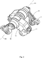
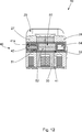
Wie aus den
In der vorliegenden Ausführungsform dienen die schaltbaren Schwinghebel
Zum Betätigen der Gaswechselventile weisen die schaltbaren Schwinghebel
Im Folgenden werden nun die schaltbaren Schwinghebel
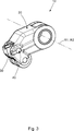
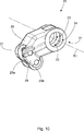
Wie aus den
Wie insbesondere aus
Wie insbesondere aus
Wie insbesondere aus den
Wie insbesondere aus
Wie insbesondere aus
Wie z.B. aus
Wie am besten aus der Zusammenschau der
Die erste Durchgangspassage
Obwohl aus den
Wie am besten aus der Zusammenschau der
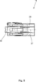
Nun wird unter besonderer Bezugnahme auf die
Genauer weist die Kupplungseinrichtung
Die Schieberanordnung
Der erste Schieber
Der zweite Schieber
Der dritte Schieber
Der dritte Schieber
Damit ist der dritte Schieber
Demgemäß wird bei Beaufschlagung der Stellkraft der zweite Schieber
Bei Wegnahme der Stellkraft wird der zweite Schieber
BezugszeichenlisteLIST OF REFERENCE NUMBERS
- 11
- Brennkraftmaschine Internal combustion engine
- 22
- Kurbelgehäuse crankcase
- 1010
- schaltbarer Schwinghebel switchable rocker arm
- 10'10 '
- nicht schaltbarer Schwinghebel non-switchable rocker arm
- 1111
- Betätigungsabschnitt actuating section
- 11'11 '
- Betätigungsabschnitt actuating section
- 2020
- erstes Hebelteil first lever part
- 2121
- erstes Schwenklager first pivot bearing
- 2222
- erste Durchgangspassage first through passage
- 2323
- Teilpassage part passage
- 2424
- Teilpassage part passage
- 25a25a
- Laufrolle caster
- 25b25b
- Laufrolle caster
- 26a26a
- Mantelfläche lateral surface
- 26b26b
- Mantelfläche lateral surface
- 2727
- Armabschnitt arm
- 2828
- Armabschnitt arm
- 2929
- Stegabschnitt web section
- 3030
- zweites Hebelteil second lever part
- 3131
- zweites Schwenklager second pivot bearing
- 3232
- zweite Durchgangspassage second passage
- 3535
- Laufrolle caster
- 3636
- Mantelfläche lateral surface
- 4040
- Kupplungseinrichtung coupling device
- 4141
- Schieberführungspassage Slide guide passage
- 41a41a
- Längsende longitudinal end
- 41b41b
- Längsende longitudinal end
- 4242
- Feder feather
- 5050
- Schieberanordnung slide arrangement
- 5151
- erster Schieber first slide
- 5252
- zweiter Schieber second slider
- 5353
- dritter Schieber third slide
- 5454
- Ölkammer oil chamber
- 5656
- Ölzulauf oil supply
- 9090
- Achsenteil axle part
- R1R1
- erste Drehachse first axis of rotation
- R2R2
- zweite Drehachse second axis of rotation
- R3R3
- Drehachse axis of rotation
- R4R4
- Drehachse axis of rotation
- R5R5
- Drehachse axis of rotation
ZITATE ENTHALTEN IN DER BESCHREIBUNG QUOTES INCLUDE IN THE DESCRIPTION
Diese Liste der vom Anmelder aufgeführten Dokumente wurde automatisiert erzeugt und ist ausschließlich zur besseren Information des Lesers aufgenommen. Die Liste ist nicht Bestandteil der deutschen Patent- bzw. Gebrauchsmusteranmeldung. Das DPMA übernimmt keinerlei Haftung für etwaige Fehler oder Auslassungen.This list of the documents listed by the applicant has been generated automatically and is included solely for the better information of the reader. The list is not part of the German patent or utility model application. The DPMA assumes no liability for any errors or omissions.
Zitierte PatentliteraturCited patent literature
- EP 1785595 A1 [0003] EP 1785595 A1 [0003]
Claims (10)
Priority Applications (3)
| Application Number | Priority Date | Filing Date | Title |
|---|---|---|---|
| DE102012204367A DE102012204367A1 (en) | 2012-03-20 | 2012-03-20 | Switchable rocker arm |
| EP13154088.2A EP2642094B1 (en) | 2012-03-20 | 2013-02-05 | Switchable swing arm |
| NO13782936A NO2888113T3 (en) | 2012-03-20 | 2013-08-21 |
Applications Claiming Priority (1)
| Application Number | Priority Date | Filing Date | Title |
|---|---|---|---|
| DE102012204367A DE102012204367A1 (en) | 2012-03-20 | 2012-03-20 | Switchable rocker arm |
Publications (1)
| Publication Number | Publication Date |
|---|---|
| DE102012204367A1 true DE102012204367A1 (en) | 2013-09-26 |
Family
ID=47720332
Family Applications (1)
| Application Number | Title | Priority Date | Filing Date |
|---|---|---|---|
| DE102012204367A Withdrawn DE102012204367A1 (en) | 2012-03-20 | 2012-03-20 | Switchable rocker arm |
Country Status (3)
| Country | Link |
|---|---|
| EP (1) | EP2642094B1 (en) |
| DE (1) | DE102012204367A1 (en) |
| NO (1) | NO2888113T3 (en) |
Cited By (1)
| Publication number | Priority date | Publication date | Assignee | Title |
|---|---|---|---|---|
| DE102016113054A1 (en) | 2016-07-15 | 2018-01-18 | Man Diesel & Turbo Se | Internal combustion engine and modular system for a valve train of an internal combustion engine |
Citations (10)
| Publication number | Priority date | Publication date | Assignee | Title |
|---|---|---|---|---|
| JPS6436904A (en) * | 1987-07-31 | 1989-02-07 | Honda Motor Co Ltd | Valve system for multicylinder internal combustion engine |
| EP0652353A1 (en) * | 1993-11-08 | 1995-05-10 | Mercedes-Benz Ag | Device for operating the valves of an internal combustion engine |
| DE19652765A1 (en) * | 1995-12-20 | 1997-06-26 | Iav Motor Gmbh | Valve drive with roller rocker arms |
| DE10155801A1 (en) * | 2001-11-14 | 2003-05-22 | Ina Schaeffler Kg | Rocker arm used in a valve gear of an internal combustion engine comprises an external rocker having an inner rocker positioned between its arms which pivot relative to each other |
| EP1785595A1 (en) | 2005-11-10 | 2007-05-16 | Schaeffler KG | Switchable rocker arm of a valve train of an internal combustion engine |
| DE102007008790A1 (en) * | 2006-12-14 | 2008-06-19 | Hyundai Motor Company | Variable valve lift |
| DE102008013802A1 (en) * | 2007-03-13 | 2008-10-16 | GM Global Technology Operations, Inc., Detroit | Two-stage rocker arm assembly |
| DE102009038249A1 (en) * | 2008-08-25 | 2010-04-08 | GM Global Technology Operations, Inc., Detroit | Cam follower assembly |
| DE102011014280A1 (en) * | 2010-03-22 | 2011-11-03 | Gm Global Technology Operations, Inc. | Motor with a valve drive with variable stroke |
| EP2397660A2 (en) * | 2010-06-15 | 2011-12-21 | Kwang Yang Motor Co., Ltd. | Structure of driving member of engine valve |
Family Cites Families (10)
| Publication number | Priority date | Publication date | Assignee | Title |
|---|---|---|---|---|
| JPS63100211A (en) * | 1986-10-15 | 1988-05-02 | Honda Motor Co Ltd | Valve mechanism of internal combustion engine |
| GB2199894B (en) * | 1987-01-08 | 1990-10-24 | Honda Motor Co Ltd | Valve operating device in internal combustion engine |
| US5253621A (en) * | 1992-08-14 | 1993-10-19 | Group Lotus Plc | Valve control means |
| DE19637066A1 (en) * | 1996-09-12 | 1998-03-19 | Mwp Mahle J Wizemann Pleuco Gm | Valve operating device with stop function |
| US6257187B1 (en) * | 1999-05-06 | 2001-07-10 | Caterpillar Inc. | Pivot shaft for an internal combustion engine |
| US6644254B2 (en) * | 2001-01-17 | 2003-11-11 | Honda Giken Kogyo Kabushiki Kaisha | Valve train for internal combustion engine |
| US6705259B1 (en) * | 2002-12-10 | 2004-03-16 | Delphi Technologies, Inc. | 3-step cam-profile-switching roller finger follower |
| TWI237087B (en) * | 2002-12-17 | 2005-08-01 | Mitsubishi Motors Corp | Valve system for internal combustion engine |
| US7007650B2 (en) * | 2003-10-31 | 2006-03-07 | Caterpillar Inc | Engine valve actuation system |
| US7404386B1 (en) * | 2007-02-13 | 2008-07-29 | Gm Global Technology Operations, Inc. | Multi-step valve actuation system |
-
2012
- 2012-03-20 DE DE102012204367A patent/DE102012204367A1/en not_active Withdrawn
-
2013
- 2013-02-05 EP EP13154088.2A patent/EP2642094B1/en active Active
- 2013-08-21 NO NO13782936A patent/NO2888113T3/no unknown
Patent Citations (10)
| Publication number | Priority date | Publication date | Assignee | Title |
|---|---|---|---|---|
| JPS6436904A (en) * | 1987-07-31 | 1989-02-07 | Honda Motor Co Ltd | Valve system for multicylinder internal combustion engine |
| EP0652353A1 (en) * | 1993-11-08 | 1995-05-10 | Mercedes-Benz Ag | Device for operating the valves of an internal combustion engine |
| DE19652765A1 (en) * | 1995-12-20 | 1997-06-26 | Iav Motor Gmbh | Valve drive with roller rocker arms |
| DE10155801A1 (en) * | 2001-11-14 | 2003-05-22 | Ina Schaeffler Kg | Rocker arm used in a valve gear of an internal combustion engine comprises an external rocker having an inner rocker positioned between its arms which pivot relative to each other |
| EP1785595A1 (en) | 2005-11-10 | 2007-05-16 | Schaeffler KG | Switchable rocker arm of a valve train of an internal combustion engine |
| DE102007008790A1 (en) * | 2006-12-14 | 2008-06-19 | Hyundai Motor Company | Variable valve lift |
| DE102008013802A1 (en) * | 2007-03-13 | 2008-10-16 | GM Global Technology Operations, Inc., Detroit | Two-stage rocker arm assembly |
| DE102009038249A1 (en) * | 2008-08-25 | 2010-04-08 | GM Global Technology Operations, Inc., Detroit | Cam follower assembly |
| DE102011014280A1 (en) * | 2010-03-22 | 2011-11-03 | Gm Global Technology Operations, Inc. | Motor with a valve drive with variable stroke |
| EP2397660A2 (en) * | 2010-06-15 | 2011-12-21 | Kwang Yang Motor Co., Ltd. | Structure of driving member of engine valve |
Cited By (1)
| Publication number | Priority date | Publication date | Assignee | Title |
|---|---|---|---|---|
| DE102016113054A1 (en) | 2016-07-15 | 2018-01-18 | Man Diesel & Turbo Se | Internal combustion engine and modular system for a valve train of an internal combustion engine |
Also Published As
| Publication number | Publication date |
|---|---|
| NO2888113T3 (en) | 2018-07-21 |
| EP2642094A1 (en) | 2013-09-25 |
| EP2642094B1 (en) | 2017-07-19 |
Similar Documents
| Publication | Publication Date | Title |
|---|---|---|
| DE102007027979B4 (en) | Valve train for gas exchange valves of an internal combustion engine with camshaft tunnel bearings | |
| EP2132418B1 (en) | Valve drive for gas exchange valves of an internal combustion engine, comprising a movable cam support and a twin worm gear | |
| DE102007010148A1 (en) | Valve gear for internal combustion engine, includes bearing which can be slid along cam shaft with cam carriers, relative to engine casing | |
| DE102015106978A1 (en) | Multi-variable valve lift | |
| EP2013450A1 (en) | Switchable cam follower of a valve train assembly of an internal combustion engine | |
| DE102006054168A1 (en) | Two-stage rocker arm with roller element cam followers | |
| DE102011077024A1 (en) | Drag lever for actuating a gas exchange valve | |
| DE102007010155A1 (en) | Camshaft for IC engine has two cam followers plus a circular cam which slides axially into the cam bearing for the non operating valve setting | |
| DE102007010150A1 (en) | Valve drive for gas exchange valves has locking device fixed in position in housing of internal combustion engine | |
| DE102012105795A1 (en) | Valve train of internal combustion engine, has orientation unit that is cooperated with guide element and is elastically expanded under action of guide element from stroke curve to define axially extended position | |
| DE102012012150B4 (en) | Rocker arm arrangement and internal combustion engine | |
| DE102016212480A1 (en) | Variable valve train of a combustion piston engine | |
| EP2642094B1 (en) | Switchable swing arm | |
| DE102004005594A1 (en) | Cam follower for stroke changeover | |
| DE102011085708A1 (en) | Switchable lever like cam follower assembly for valve train of internal combustion engine, has control contour that moves from unlocked position to coupling position upon movement of control element relative to outer lever | |
| DE102018210521A1 (en) | Variable valve actuator | |
| DE102017130277A1 (en) | Switchable cam follower of a valve train | |
| DE102016220396A1 (en) | Intermediate lever of a variable valve train | |
| DE102010034201A1 (en) | Roller cam for actuating gas exchange valve of internal combustion engine, has side walls provided in region of cam roller | |
| DE102008015218A1 (en) | Valve mechanism of an engine | |
| DE102009018671A1 (en) | Detachable roller lever for use in internal combustion engine, has external housing, which stands in interference with end with hydraulic clearance compensation element, and stands in interference with another end with valve shaft | |
| DE102018112815A1 (en) | Variable valve train of a reciprocating internal combustion engine | |
| DE102017127546A1 (en) | Switchable cam follower of a valve train of an internal combustion engine | |
| DE102005038505B3 (en) | Forced-control valve train | |
| DE102011085709A1 (en) | Switchable lever-like cam follower i.e. switchable rocker arm, for variable valve train of single-cylinder engine of motor cycle, has control body whose contour is transferred to coupling position upon movement of body to operation position |
Legal Events
| Date | Code | Title | Description |
|---|---|---|---|
| R163 | Identified publications notified | ||
| R120 | Application withdrawn or ip right abandoned |