DE102010034322A1 - Surface modified silicate phosphors - Google Patents
Surface modified silicate phosphors Download PDFInfo
- Publication number
- DE102010034322A1 DE102010034322A1 DE102010034322A DE102010034322A DE102010034322A1 DE 102010034322 A1 DE102010034322 A1 DE 102010034322A1 DE 102010034322 A DE102010034322 A DE 102010034322A DE 102010034322 A DE102010034322 A DE 102010034322A DE 102010034322 A1 DE102010034322 A1 DE 102010034322A1
- Authority
- DE
- Germany
- Prior art keywords
- phosphors
- fluorine
- phosphor
- silicate phosphors
- alkaline earth
- Prior art date
- Legal status (The legal status is an assumption and is not a legal conclusion. Google has not performed a legal analysis and makes no representation as to the accuracy of the status listed.)
- Withdrawn
Links
- 150000004760 silicates Chemical class 0.000 title claims abstract description 12
- OAICVXFJPJFONN-UHFFFAOYSA-N Phosphorus Chemical compound [P] OAICVXFJPJFONN-UHFFFAOYSA-N 0.000 claims abstract description 59
- 229910052731 fluorine Inorganic materials 0.000 claims abstract description 30
- YCKRFDGAMUMZLT-UHFFFAOYSA-N Fluorine atom Chemical compound [F] YCKRFDGAMUMZLT-UHFFFAOYSA-N 0.000 claims abstract description 24
- 239000011737 fluorine Substances 0.000 claims abstract description 24
- BPQQTUXANYXVAA-UHFFFAOYSA-N Orthosilicate Chemical compound [O-][Si]([O-])([O-])[O-] BPQQTUXANYXVAA-UHFFFAOYSA-N 0.000 claims abstract description 20
- 239000000463 material Substances 0.000 claims abstract description 17
- 230000005855 radiation Effects 0.000 claims abstract description 13
- 239000011159 matrix material Substances 0.000 claims abstract description 12
- 230000015572 biosynthetic process Effects 0.000 claims abstract description 11
- 238000003682 fluorination reaction Methods 0.000 claims abstract description 8
- 239000011241 protective layer Substances 0.000 claims abstract description 8
- 230000007613 environmental effect Effects 0.000 claims abstract description 6
- 239000003795 chemical substances by application Substances 0.000 claims abstract description 5
- 239000011521 glass Substances 0.000 claims abstract description 5
- 230000007547 defect Effects 0.000 claims abstract description 4
- 230000000694 effects Effects 0.000 claims abstract description 4
- 229910052688 Gadolinium Inorganic materials 0.000 claims abstract description 3
- 229910052765 Lutetium Inorganic materials 0.000 claims abstract description 3
- 230000004888 barrier function Effects 0.000 claims abstract description 3
- 239000003086 colorant Substances 0.000 claims abstract description 3
- 238000009833 condensation Methods 0.000 claims abstract description 3
- 230000005494 condensation Effects 0.000 claims abstract description 3
- 230000007062 hydrolysis Effects 0.000 claims abstract description 3
- 238000006460 hydrolysis reaction Methods 0.000 claims abstract description 3
- 230000002209 hydrophobic effect Effects 0.000 claims abstract description 3
- 238000003384 imaging method Methods 0.000 claims abstract description 3
- 229910052746 lanthanum Inorganic materials 0.000 claims abstract description 3
- 239000013110 organic ligand Substances 0.000 claims abstract description 3
- 150000001282 organosilanes Chemical class 0.000 claims abstract description 3
- 229910052727 yttrium Inorganic materials 0.000 claims abstract description 3
- 230000005923 long-lasting effect Effects 0.000 claims abstract 2
- 229910004298 SiO 2 Inorganic materials 0.000 claims description 16
- LIVNPJMFVYWSIS-UHFFFAOYSA-N silicon monoxide Chemical compound [Si-]#[O+] LIVNPJMFVYWSIS-UHFFFAOYSA-N 0.000 claims description 13
- -1 N) z: A Inorganic materials 0.000 claims description 10
- 239000011248 coating agent Substances 0.000 claims description 9
- 238000000576 coating method Methods 0.000 claims description 9
- 238000004020 luminiscence type Methods 0.000 claims description 9
- 150000001875 compounds Chemical class 0.000 claims description 8
- 229910052710 silicon Inorganic materials 0.000 claims description 8
- 229910052751 metal Inorganic materials 0.000 claims description 7
- 239000002184 metal Substances 0.000 claims description 7
- 229910052757 nitrogen Inorganic materials 0.000 claims description 7
- XUIMIQQOPSSXEZ-UHFFFAOYSA-N Silicon Chemical compound [Si] XUIMIQQOPSSXEZ-UHFFFAOYSA-N 0.000 claims description 6
- 229910052796 boron Inorganic materials 0.000 claims description 6
- 238000005516 engineering process Methods 0.000 claims description 6
- 229910052732 germanium Inorganic materials 0.000 claims description 6
- 229910052698 phosphorus Inorganic materials 0.000 claims description 6
- 239000010703 silicon Substances 0.000 claims description 6
- 229910052717 sulfur Inorganic materials 0.000 claims description 6
- 229910052720 vanadium Inorganic materials 0.000 claims description 6
- 150000002500 ions Chemical class 0.000 claims description 5
- 239000012190 activator Substances 0.000 claims description 4
- 229910052747 lanthanoid Inorganic materials 0.000 claims description 4
- 150000002602 lanthanoids Chemical class 0.000 claims description 4
- 239000002243 precursor Substances 0.000 claims description 4
- 229910018072 Al 2 O 3 Inorganic materials 0.000 claims description 3
- 229910052760 oxygen Inorganic materials 0.000 claims description 3
- 229910052783 alkali metal Inorganic materials 0.000 claims description 2
- 150000001340 alkali metals Chemical class 0.000 claims description 2
- 229910052782 aluminium Inorganic materials 0.000 claims description 2
- 229910052799 carbon Inorganic materials 0.000 claims description 2
- 150000001768 cations Chemical class 0.000 claims description 2
- 229910052749 magnesium Inorganic materials 0.000 claims description 2
- WPBNNNQJVZRUHP-UHFFFAOYSA-L manganese(2+);methyl n-[[2-(methoxycarbonylcarbamothioylamino)phenyl]carbamothioyl]carbamate;n-[2-(sulfidocarbothioylamino)ethyl]carbamodithioate Chemical compound [Mn+2].[S-]C(=S)NCCNC([S-])=S.COC(=O)NC(=S)NC1=CC=CC=C1NC(=S)NC(=O)OC WPBNNNQJVZRUHP-UHFFFAOYSA-L 0.000 claims description 2
- 230000000737 periodic effect Effects 0.000 claims description 2
- 229910052725 zinc Inorganic materials 0.000 claims description 2
- XLYOFNOQVPJJNP-UHFFFAOYSA-N water Substances O XLYOFNOQVPJJNP-UHFFFAOYSA-N 0.000 abstract description 5
- VYPSYNLAJGMNEJ-UHFFFAOYSA-N Silicium dioxide Chemical compound O=[Si]=O VYPSYNLAJGMNEJ-UHFFFAOYSA-N 0.000 abstract description 3
- 229910052593 corundum Inorganic materials 0.000 abstract description 3
- PNEYBMLMFCGWSK-UHFFFAOYSA-N aluminium oxide Inorganic materials [O-2].[O-2].[O-2].[Al+3].[Al+3] PNEYBMLMFCGWSK-UHFFFAOYSA-N 0.000 abstract 1
- 229910052681 coesite Inorganic materials 0.000 abstract 1
- 229910052906 cristobalite Inorganic materials 0.000 abstract 1
- 239000000377 silicon dioxide Substances 0.000 abstract 1
- 235000012239 silicon dioxide Nutrition 0.000 abstract 1
- 229910052682 stishovite Inorganic materials 0.000 abstract 1
- 229910052905 tridymite Inorganic materials 0.000 abstract 1
- 229910001845 yogo sapphire Inorganic materials 0.000 abstract 1
- 239000000203 mixture Substances 0.000 description 20
- 230000003287 optical effect Effects 0.000 description 13
- 229910017855 NH 4 F Inorganic materials 0.000 description 12
- 238000000034 method Methods 0.000 description 11
- LFQSCWFLJHTTHZ-UHFFFAOYSA-N Ethanol Chemical compound CCO LFQSCWFLJHTTHZ-UHFFFAOYSA-N 0.000 description 10
- 238000000295 emission spectrum Methods 0.000 description 10
- 238000002360 preparation method Methods 0.000 description 10
- 238000000137 annealing Methods 0.000 description 8
- 239000002245 particle Substances 0.000 description 7
- 230000008569 process Effects 0.000 description 7
- 238000006243 chemical reaction Methods 0.000 description 6
- 239000000843 powder Substances 0.000 description 6
- 238000004381 surface treatment Methods 0.000 description 6
- UFHFLCQGNIYNRP-UHFFFAOYSA-N Hydrogen Chemical compound [H][H] UFHFLCQGNIYNRP-UHFFFAOYSA-N 0.000 description 5
- KDLHZDBZIXYQEI-UHFFFAOYSA-N Palladium Chemical compound [Pd] KDLHZDBZIXYQEI-UHFFFAOYSA-N 0.000 description 5
- BOTDANWDWHJENH-UHFFFAOYSA-N Tetraethyl orthosilicate Chemical compound CCO[Si](OCC)(OCC)OCC BOTDANWDWHJENH-UHFFFAOYSA-N 0.000 description 5
- 239000002585 base Substances 0.000 description 5
- 238000001816 cooling Methods 0.000 description 5
- 238000000635 electron micrograph Methods 0.000 description 5
- 239000012025 fluorinating agent Substances 0.000 description 5
- 150000002222 fluorine compounds Chemical class 0.000 description 5
- 229910052739 hydrogen Inorganic materials 0.000 description 5
- 239000001257 hydrogen Substances 0.000 description 5
- 239000007858 starting material Substances 0.000 description 5
- 229910004283 SiO 4 Inorganic materials 0.000 description 4
- 238000001035 drying Methods 0.000 description 4
- 238000011835 investigation Methods 0.000 description 4
- 238000007873 sieving Methods 0.000 description 4
- 239000000126 substance Substances 0.000 description 4
- 238000003786 synthesis reaction Methods 0.000 description 4
- 229910016569 AlF 3 Inorganic materials 0.000 description 3
- 229910052693 Europium Inorganic materials 0.000 description 3
- 238000004833 X-ray photoelectron spectroscopy Methods 0.000 description 3
- 238000000026 X-ray photoelectron spectrum Methods 0.000 description 3
- 229910052784 alkaline earth metal Inorganic materials 0.000 description 3
- 239000012298 atmosphere Substances 0.000 description 3
- 230000000052 comparative effect Effects 0.000 description 3
- 238000002149 energy-dispersive X-ray emission spectroscopy Methods 0.000 description 3
- 230000004907 flux Effects 0.000 description 3
- 239000010931 gold Substances 0.000 description 3
- 238000005259 measurement Methods 0.000 description 3
- 239000012925 reference material Substances 0.000 description 3
- 229910052712 strontium Inorganic materials 0.000 description 3
- CIOAGBVUUVVLOB-UHFFFAOYSA-N strontium atom Chemical compound [Sr] CIOAGBVUUVVLOB-UHFFFAOYSA-N 0.000 description 3
- VHUUQVKOLVNVRT-UHFFFAOYSA-N Ammonium hydroxide Chemical compound [NH4+].[OH-] VHUUQVKOLVNVRT-UHFFFAOYSA-N 0.000 description 2
- 239000003513 alkali Substances 0.000 description 2
- 235000011114 ammonium hydroxide Nutrition 0.000 description 2
- 239000011324 bead Substances 0.000 description 2
- 238000005229 chemical vapour deposition Methods 0.000 description 2
- 239000010431 corundum Substances 0.000 description 2
- 238000009826 distribution Methods 0.000 description 2
- 239000007789 gas Substances 0.000 description 2
- PCHJSUWPFVWCPO-UHFFFAOYSA-N gold Chemical compound [Au] PCHJSUWPFVWCPO-UHFFFAOYSA-N 0.000 description 2
- 229910052737 gold Inorganic materials 0.000 description 2
- 150000004820 halides Chemical class 0.000 description 2
- 239000000320 mechanical mixture Substances 0.000 description 2
- 229910052763 palladium Inorganic materials 0.000 description 2
- 239000000047 product Substances 0.000 description 2
- 238000001878 scanning electron micrograph Methods 0.000 description 2
- 230000035945 sensitivity Effects 0.000 description 2
- 238000003746 solid phase reaction Methods 0.000 description 2
- 238000010671 solid-state reaction Methods 0.000 description 2
- 238000001228 spectrum Methods 0.000 description 2
- 239000002344 surface layer Substances 0.000 description 2
- 239000000725 suspension Substances 0.000 description 2
- 238000005406 washing Methods 0.000 description 2
- BUHVIAUBTBOHAG-FOYDDCNASA-N (2r,3r,4s,5r)-2-[6-[[2-(3,5-dimethoxyphenyl)-2-(2-methylphenyl)ethyl]amino]purin-9-yl]-5-(hydroxymethyl)oxolane-3,4-diol Chemical compound COC1=CC(OC)=CC(C(CNC=2C=3N=CN(C=3N=CN=2)[C@H]2[C@@H]([C@H](O)[C@@H](CO)O2)O)C=2C(=CC=CC=2)C)=C1 BUHVIAUBTBOHAG-FOYDDCNASA-N 0.000 description 1
- IRPGOXJVTQTAAN-UHFFFAOYSA-N 2,2,3,3,3-pentafluoropropanal Chemical compound FC(F)(F)C(F)(F)C=O IRPGOXJVTQTAAN-UHFFFAOYSA-N 0.000 description 1
- KLZUFWVZNOTSEM-UHFFFAOYSA-K Aluminum fluoride Inorganic materials F[Al](F)F KLZUFWVZNOTSEM-UHFFFAOYSA-K 0.000 description 1
- 229910016036 BaF 2 Inorganic materials 0.000 description 1
- 229910004261 CaF 2 Inorganic materials 0.000 description 1
- 229910005690 GdF 3 Inorganic materials 0.000 description 1
- 229910017768 LaF 3 Inorganic materials 0.000 description 1
- 229910017639 MgSi Inorganic materials 0.000 description 1
- 229910052581 Si3N4 Inorganic materials 0.000 description 1
- 239000000654 additive Substances 0.000 description 1
- 150000001341 alkaline earth metal compounds Chemical class 0.000 description 1
- 238000004458 analytical method Methods 0.000 description 1
- 150000001450 anions Chemical class 0.000 description 1
- 239000007900 aqueous suspension Substances 0.000 description 1
- QVGXLLKOCUKJST-UHFFFAOYSA-N atomic oxygen Chemical compound [O] QVGXLLKOCUKJST-UHFFFAOYSA-N 0.000 description 1
- 230000033558 biomineral tissue development Effects 0.000 description 1
- 239000008367 deionised water Substances 0.000 description 1
- 229910021641 deionized water Inorganic materials 0.000 description 1
- 230000001419 dependent effect Effects 0.000 description 1
- 238000001514 detection method Methods 0.000 description 1
- 238000005538 encapsulation Methods 0.000 description 1
- 238000000724 energy-dispersive X-ray spectrum Methods 0.000 description 1
- OGPBJKLSAFTDLK-UHFFFAOYSA-N europium atom Chemical compound [Eu] OGPBJKLSAFTDLK-UHFFFAOYSA-N 0.000 description 1
- 230000005284 excitation Effects 0.000 description 1
- 238000000605 extraction Methods 0.000 description 1
- 239000012467 final product Substances 0.000 description 1
- 238000004334 fluoridation Methods 0.000 description 1
- 238000010438 heat treatment Methods 0.000 description 1
- 238000000265 homogenisation Methods 0.000 description 1
- 238000010348 incorporation Methods 0.000 description 1
- 230000003993 interaction Effects 0.000 description 1
- 229910044991 metal oxide Inorganic materials 0.000 description 1
- 150000004706 metal oxides Chemical class 0.000 description 1
- 150000002739 metals Chemical class 0.000 description 1
- 238000002156 mixing Methods 0.000 description 1
- 238000012986 modification Methods 0.000 description 1
- 230000004048 modification Effects 0.000 description 1
- 229910052605 nesosilicate Inorganic materials 0.000 description 1
- 239000012299 nitrogen atmosphere Substances 0.000 description 1
- 150000004812 organic fluorine compounds Chemical class 0.000 description 1
- 229920000620 organic polymer Polymers 0.000 description 1
- 239000001301 oxygen Substances 0.000 description 1
- 235000012771 pancakes Nutrition 0.000 description 1
- 239000004033 plastic Substances 0.000 description 1
- 229910052761 rare earth metal Inorganic materials 0.000 description 1
- 239000000376 reactant Substances 0.000 description 1
- 239000011541 reaction mixture Substances 0.000 description 1
- 230000035484 reaction time Effects 0.000 description 1
- 230000009257 reactivity Effects 0.000 description 1
- 238000000926 separation method Methods 0.000 description 1
- HQVNEWCFYHHQES-UHFFFAOYSA-N silicon nitride Chemical compound N12[Si]34N5[Si]62N3[Si]51N64 HQVNEWCFYHHQES-UHFFFAOYSA-N 0.000 description 1
- 229910052814 silicon oxide Inorganic materials 0.000 description 1
- 239000002904 solvent Substances 0.000 description 1
- 230000003595 spectral effect Effects 0.000 description 1
- 238000013112 stability test Methods 0.000 description 1
- 238000003756 stirring Methods 0.000 description 1
- 239000006228 supernatant Substances 0.000 description 1
- 238000005496 tempering Methods 0.000 description 1
Images


Classifications
-
- C—CHEMISTRY; METALLURGY
- C09—DYES; PAINTS; POLISHES; NATURAL RESINS; ADHESIVES; COMPOSITIONS NOT OTHERWISE PROVIDED FOR; APPLICATIONS OF MATERIALS NOT OTHERWISE PROVIDED FOR
- C09K—MATERIALS FOR MISCELLANEOUS APPLICATIONS, NOT PROVIDED FOR ELSEWHERE
- C09K11/00—Luminescent, e.g. electroluminescent, chemiluminescent materials
- C09K11/02—Use of particular materials as binders, particle coatings or suspension media therefor
- C09K11/025—Use of particular materials as binders, particle coatings or suspension media therefor non-luminescent particle coatings or suspension media
-
- C—CHEMISTRY; METALLURGY
- C09—DYES; PAINTS; POLISHES; NATURAL RESINS; ADHESIVES; COMPOSITIONS NOT OTHERWISE PROVIDED FOR; APPLICATIONS OF MATERIALS NOT OTHERWISE PROVIDED FOR
- C09K—MATERIALS FOR MISCELLANEOUS APPLICATIONS, NOT PROVIDED FOR ELSEWHERE
- C09K11/00—Luminescent, e.g. electroluminescent, chemiluminescent materials
- C09K11/08—Luminescent, e.g. electroluminescent, chemiluminescent materials containing inorganic luminescent materials
- C09K11/77—Luminescent, e.g. electroluminescent, chemiluminescent materials containing inorganic luminescent materials containing rare earth metals
- C09K11/7728—Luminescent, e.g. electroluminescent, chemiluminescent materials containing inorganic luminescent materials containing rare earth metals containing europium
- C09K11/7734—Aluminates
-
- C—CHEMISTRY; METALLURGY
- C09—DYES; PAINTS; POLISHES; NATURAL RESINS; ADHESIVES; COMPOSITIONS NOT OTHERWISE PROVIDED FOR; APPLICATIONS OF MATERIALS NOT OTHERWISE PROVIDED FOR
- C09K—MATERIALS FOR MISCELLANEOUS APPLICATIONS, NOT PROVIDED FOR ELSEWHERE
- C09K11/00—Luminescent, e.g. electroluminescent, chemiluminescent materials
- C09K11/08—Luminescent, e.g. electroluminescent, chemiluminescent materials containing inorganic luminescent materials
- C09K11/77—Luminescent, e.g. electroluminescent, chemiluminescent materials containing inorganic luminescent materials containing rare earth metals
- C09K11/7728—Luminescent, e.g. electroluminescent, chemiluminescent materials containing inorganic luminescent materials containing rare earth metals containing europium
- C09K11/77342—Silicates
-
- H—ELECTRICITY
- H01—ELECTRIC ELEMENTS
- H01L—SEMICONDUCTOR DEVICES NOT COVERED BY CLASS H10
- H01L25/00—Assemblies consisting of a plurality of individual semiconductor or other solid state devices ; Multistep manufacturing processes thereof
- H01L25/03—Assemblies consisting of a plurality of individual semiconductor or other solid state devices ; Multistep manufacturing processes thereof all the devices being of a type provided for in the same subgroup of groups H01L27/00 - H01L33/00, or in a single subclass of H10K, H10N, e.g. assemblies of rectifier diodes
- H01L25/04—Assemblies consisting of a plurality of individual semiconductor or other solid state devices ; Multistep manufacturing processes thereof all the devices being of a type provided for in the same subgroup of groups H01L27/00 - H01L33/00, or in a single subclass of H10K, H10N, e.g. assemblies of rectifier diodes the devices not having separate containers
- H01L25/075—Assemblies consisting of a plurality of individual semiconductor or other solid state devices ; Multistep manufacturing processes thereof all the devices being of a type provided for in the same subgroup of groups H01L27/00 - H01L33/00, or in a single subclass of H10K, H10N, e.g. assemblies of rectifier diodes the devices not having separate containers the devices being of a type provided for in group H01L33/00
- H01L25/0753—Assemblies consisting of a plurality of individual semiconductor or other solid state devices ; Multistep manufacturing processes thereof all the devices being of a type provided for in the same subgroup of groups H01L27/00 - H01L33/00, or in a single subclass of H10K, H10N, e.g. assemblies of rectifier diodes the devices not having separate containers the devices being of a type provided for in group H01L33/00 the devices being arranged next to each other
-
- H—ELECTRICITY
- H01—ELECTRIC ELEMENTS
- H01L—SEMICONDUCTOR DEVICES NOT COVERED BY CLASS H10
- H01L33/00—Semiconductor devices having potential barriers specially adapted for light emission; Processes or apparatus specially adapted for the manufacture or treatment thereof or of parts thereof; Details thereof
- H01L33/48—Semiconductor devices having potential barriers specially adapted for light emission; Processes or apparatus specially adapted for the manufacture or treatment thereof or of parts thereof; Details thereof characterised by the semiconductor body packages
- H01L33/483—Containers
- H01L33/486—Containers adapted for surface mounting
-
- H—ELECTRICITY
- H01—ELECTRIC ELEMENTS
- H01L—SEMICONDUCTOR DEVICES NOT COVERED BY CLASS H10
- H01L33/00—Semiconductor devices having potential barriers specially adapted for light emission; Processes or apparatus specially adapted for the manufacture or treatment thereof or of parts thereof; Details thereof
- H01L33/48—Semiconductor devices having potential barriers specially adapted for light emission; Processes or apparatus specially adapted for the manufacture or treatment thereof or of parts thereof; Details thereof characterised by the semiconductor body packages
- H01L33/50—Wavelength conversion elements
- H01L33/501—Wavelength conversion elements characterised by the materials, e.g. binder
- H01L33/502—Wavelength conversion materials
-
- H—ELECTRICITY
- H01—ELECTRIC ELEMENTS
- H01L—SEMICONDUCTOR DEVICES NOT COVERED BY CLASS H10
- H01L33/00—Semiconductor devices having potential barriers specially adapted for light emission; Processes or apparatus specially adapted for the manufacture or treatment thereof or of parts thereof; Details thereof
- H01L33/48—Semiconductor devices having potential barriers specially adapted for light emission; Processes or apparatus specially adapted for the manufacture or treatment thereof or of parts thereof; Details thereof characterised by the semiconductor body packages
- H01L33/50—Wavelength conversion elements
- H01L33/507—Wavelength conversion elements the elements being in intimate contact with parts other than the semiconductor body or integrated with parts other than the semiconductor body
-
- H—ELECTRICITY
- H01—ELECTRIC ELEMENTS
- H01L—SEMICONDUCTOR DEVICES NOT COVERED BY CLASS H10
- H01L33/00—Semiconductor devices having potential barriers specially adapted for light emission; Processes or apparatus specially adapted for the manufacture or treatment thereof or of parts thereof; Details thereof
- H01L33/48—Semiconductor devices having potential barriers specially adapted for light emission; Processes or apparatus specially adapted for the manufacture or treatment thereof or of parts thereof; Details thereof characterised by the semiconductor body packages
- H01L33/52—Encapsulations
-
- H—ELECTRICITY
- H01—ELECTRIC ELEMENTS
- H01L—SEMICONDUCTOR DEVICES NOT COVERED BY CLASS H10
- H01L33/00—Semiconductor devices having potential barriers specially adapted for light emission; Processes or apparatus specially adapted for the manufacture or treatment thereof or of parts thereof; Details thereof
- H01L33/48—Semiconductor devices having potential barriers specially adapted for light emission; Processes or apparatus specially adapted for the manufacture or treatment thereof or of parts thereof; Details thereof characterised by the semiconductor body packages
- H01L33/64—Heat extraction or cooling elements
-
- H—ELECTRICITY
- H01—ELECTRIC ELEMENTS
- H01L—SEMICONDUCTOR DEVICES NOT COVERED BY CLASS H10
- H01L2224/00—Indexing scheme for arrangements for connecting or disconnecting semiconductor or solid-state bodies and methods related thereto as covered by H01L24/00
- H01L2224/01—Means for bonding being attached to, or being formed on, the surface to be connected, e.g. chip-to-package, die-attach, "first-level" interconnects; Manufacturing methods related thereto
- H01L2224/42—Wire connectors; Manufacturing methods related thereto
- H01L2224/47—Structure, shape, material or disposition of the wire connectors after the connecting process
- H01L2224/48—Structure, shape, material or disposition of the wire connectors after the connecting process of an individual wire connector
- H01L2224/4805—Shape
- H01L2224/4809—Loop shape
- H01L2224/48091—Arched
-
- H—ELECTRICITY
- H01—ELECTRIC ELEMENTS
- H01L—SEMICONDUCTOR DEVICES NOT COVERED BY CLASS H10
- H01L2224/00—Indexing scheme for arrangements for connecting or disconnecting semiconductor or solid-state bodies and methods related thereto as covered by H01L24/00
- H01L2224/01—Means for bonding being attached to, or being formed on, the surface to be connected, e.g. chip-to-package, die-attach, "first-level" interconnects; Manufacturing methods related thereto
- H01L2224/42—Wire connectors; Manufacturing methods related thereto
- H01L2224/47—Structure, shape, material or disposition of the wire connectors after the connecting process
- H01L2224/48—Structure, shape, material or disposition of the wire connectors after the connecting process of an individual wire connector
- H01L2224/481—Disposition
- H01L2224/48151—Connecting between a semiconductor or solid-state body and an item not being a semiconductor or solid-state body, e.g. chip-to-substrate, chip-to-passive
- H01L2224/48221—Connecting between a semiconductor or solid-state body and an item not being a semiconductor or solid-state body, e.g. chip-to-substrate, chip-to-passive the body and the item being stacked
- H01L2224/48245—Connecting between a semiconductor or solid-state body and an item not being a semiconductor or solid-state body, e.g. chip-to-substrate, chip-to-passive the body and the item being stacked the item being metallic
- H01L2224/48247—Connecting between a semiconductor or solid-state body and an item not being a semiconductor or solid-state body, e.g. chip-to-substrate, chip-to-passive the body and the item being stacked the item being metallic connecting the wire to a bond pad of the item
-
- H—ELECTRICITY
- H01—ELECTRIC ELEMENTS
- H01L—SEMICONDUCTOR DEVICES NOT COVERED BY CLASS H10
- H01L2224/00—Indexing scheme for arrangements for connecting or disconnecting semiconductor or solid-state bodies and methods related thereto as covered by H01L24/00
- H01L2224/73—Means for bonding being of different types provided for in two or more of groups H01L2224/10, H01L2224/18, H01L2224/26, H01L2224/34, H01L2224/42, H01L2224/50, H01L2224/63, H01L2224/71
- H01L2224/732—Location after the connecting process
- H01L2224/73251—Location after the connecting process on different surfaces
- H01L2224/73265—Layer and wire connectors
-
- H—ELECTRICITY
- H01—ELECTRIC ELEMENTS
- H01L—SEMICONDUCTOR DEVICES NOT COVERED BY CLASS H10
- H01L2224/00—Indexing scheme for arrangements for connecting or disconnecting semiconductor or solid-state bodies and methods related thereto as covered by H01L24/00
- H01L2224/80—Methods for connecting semiconductor or other solid state bodies using means for bonding being attached to, or being formed on, the surface to be connected
- H01L2224/85—Methods for connecting semiconductor or other solid state bodies using means for bonding being attached to, or being formed on, the surface to be connected using a wire connector
- H01L2224/85909—Post-treatment of the connector or wire bonding area
- H01L2224/8592—Applying permanent coating, e.g. protective coating
-
- H—ELECTRICITY
- H01—ELECTRIC ELEMENTS
- H01L—SEMICONDUCTOR DEVICES NOT COVERED BY CLASS H10
- H01L2924/00—Indexing scheme for arrangements or methods for connecting or disconnecting semiconductor or solid-state bodies as covered by H01L24/00
- H01L2924/15—Details of package parts other than the semiconductor or other solid state devices to be connected
- H01L2924/181—Encapsulation
-
- H—ELECTRICITY
- H01—ELECTRIC ELEMENTS
- H01L—SEMICONDUCTOR DEVICES NOT COVERED BY CLASS H10
- H01L2924/00—Indexing scheme for arrangements or methods for connecting or disconnecting semiconductor or solid-state bodies as covered by H01L24/00
- H01L2924/19—Details of hybrid assemblies other than the semiconductor or other solid state devices to be connected
- H01L2924/191—Disposition
- H01L2924/19101—Disposition of discrete passive components
- H01L2924/19107—Disposition of discrete passive components off-chip wires
-
- H—ELECTRICITY
- H01—ELECTRIC ELEMENTS
- H01L—SEMICONDUCTOR DEVICES NOT COVERED BY CLASS H10
- H01L33/00—Semiconductor devices having potential barriers specially adapted for light emission; Processes or apparatus specially adapted for the manufacture or treatment thereof or of parts thereof; Details thereof
- H01L33/48—Semiconductor devices having potential barriers specially adapted for light emission; Processes or apparatus specially adapted for the manufacture or treatment thereof or of parts thereof; Details thereof characterised by the semiconductor body packages
- H01L33/50—Wavelength conversion elements
- H01L33/501—Wavelength conversion elements characterised by the materials, e.g. binder
-
- Y—GENERAL TAGGING OF NEW TECHNOLOGICAL DEVELOPMENTS; GENERAL TAGGING OF CROSS-SECTIONAL TECHNOLOGIES SPANNING OVER SEVERAL SECTIONS OF THE IPC; TECHNICAL SUBJECTS COVERED BY FORMER USPC CROSS-REFERENCE ART COLLECTIONS [XRACs] AND DIGESTS
- Y02—TECHNOLOGIES OR APPLICATIONS FOR MITIGATION OR ADAPTATION AGAINST CLIMATE CHANGE
- Y02B—CLIMATE CHANGE MITIGATION TECHNOLOGIES RELATED TO BUILDINGS, e.g. HOUSING, HOUSE APPLIANCES OR RELATED END-USER APPLICATIONS
- Y02B20/00—Energy efficient lighting technologies, e.g. halogen lamps or gas discharge lamps
-
- Y—GENERAL TAGGING OF NEW TECHNOLOGICAL DEVELOPMENTS; GENERAL TAGGING OF CROSS-SECTIONAL TECHNOLOGIES SPANNING OVER SEVERAL SECTIONS OF THE IPC; TECHNICAL SUBJECTS COVERED BY FORMER USPC CROSS-REFERENCE ART COLLECTIONS [XRACs] AND DIGESTS
- Y10—TECHNICAL SUBJECTS COVERED BY FORMER USPC
- Y10T—TECHNICAL SUBJECTS COVERED BY FORMER US CLASSIFICATION
- Y10T428/00—Stock material or miscellaneous articles
- Y10T428/29—Coated or structually defined flake, particle, cell, strand, strand portion, rod, filament, macroscopic fiber or mass thereof
- Y10T428/2982—Particulate matter [e.g., sphere, flake, etc.]
- Y10T428/2991—Coated
- Y10T428/2993—Silicic or refractory material containing [e.g., tungsten oxide, glass, cement, etc.]
-
- Y—GENERAL TAGGING OF NEW TECHNOLOGICAL DEVELOPMENTS; GENERAL TAGGING OF CROSS-SECTIONAL TECHNOLOGIES SPANNING OVER SEVERAL SECTIONS OF THE IPC; TECHNICAL SUBJECTS COVERED BY FORMER USPC CROSS-REFERENCE ART COLLECTIONS [XRACs] AND DIGESTS
- Y10—TECHNICAL SUBJECTS COVERED BY FORMER USPC
- Y10T—TECHNICAL SUBJECTS COVERED BY FORMER US CLASSIFICATION
- Y10T428/00—Stock material or miscellaneous articles
- Y10T428/29—Coated or structually defined flake, particle, cell, strand, strand portion, rod, filament, macroscopic fiber or mass thereof
- Y10T428/2982—Particulate matter [e.g., sphere, flake, etc.]
- Y10T428/2991—Coated
- Y10T428/2998—Coated including synthetic resin or polymer
Landscapes
- Engineering & Computer Science (AREA)
- Microelectronics & Electronic Packaging (AREA)
- Chemical & Material Sciences (AREA)
- Power Engineering (AREA)
- Computer Hardware Design (AREA)
- Manufacturing & Machinery (AREA)
- Organic Chemistry (AREA)
- Materials Engineering (AREA)
- Inorganic Chemistry (AREA)
- Physics & Mathematics (AREA)
- Condensed Matter Physics & Semiconductors (AREA)
- General Physics & Mathematics (AREA)
- Luminescent Compositions (AREA)
- Led Device Packages (AREA)
- Silicates, Zeolites, And Molecular Sieves (AREA)
- Paints Or Removers (AREA)
- Surface Treatment Of Glass (AREA)
- Laminated Bodies (AREA)
Abstract
Die Oberfläche der Leuchtstoffe auf Basis von dotierten Erdalkalisilikat-Verbindungen ist mit einer Kombination aus fluorhaltigen anorganischen oder organischen Agenzien zur Vermeidung von hydrophobisieren und störende Oberflächendefekte und einer oder mehreren die Feuchtigkeit sperrenden Schutzschichten aus schichtbildende Materialien wie die Oxide MgO, Al2O3, Ln2O3 (Ln = Y, La, Gd, Lu) und SiO2 überzogen. Zur Fluorisierung der Erdalkalisilikat-Luminophore werden fluorfunktionalisierte Organosilane der Form Si(OR)3X, eingesetzt, wobei R = CH3, C2H5, und ähnliches und X = F-funktionalisierter organischer Ligand sind. Durch gezielte Hydrolyse und Kondensation wird die Ausbildung einer fluorhaltigen Schutzschicht auf der silikatischen Leuchtstoffmatrix erreicht, die neben der Barrierewirkung zugleich hydrophobe Eigenschaften aufweist. Wegen ihrer verbesserten Beständigkeit gegenüber Wasser, Luftfeuchtigkeit und anderen Umweltfaktoren eignen sie sich besonders für den Einsatz in langlebigen technischen Erzeugnissen, beispielweise in Kathodenstrahlröhren und anderen Bilderzeugungssystemen (Scanning Laser Beam Systems), in Röntgenbildwandlern, in Hochleistungslichtquellen aller Art, vorzugsweise in LED aller Farben für die Innen- und Außenbeleuchtung sowie in der Hintergrundbeleuchtung von LCD-Displays, aber auch in Solarzellen oder Gewächshausfolien und -gläsern als Strahlungskonverter.The surface of the phosphors based on doped alkaline earth silicate compounds is made with a combination of fluorine-containing inorganic or organic agents to avoid hydrophobizing and disruptive surface defects and one or more protective layers made of layer-forming materials such as the oxides MgO, Al2O3, Ln2O3 (Ln = Y, La, Gd, Lu) and SiO2 coated. Fluorine-functionalized organosilanes of the form Si (OR) 3X, where R = CH3, C2H5, and the like and X = F-functionalized organic ligand, are used for the fluorination of the alkaline earth silicate luminophores. Through targeted hydrolysis and condensation, the formation of a fluorine-containing protective layer on the silicate phosphor matrix is achieved, which in addition to the barrier effect also has hydrophobic properties. Because of their improved resistance to water, air humidity and other environmental factors, they are particularly suitable for use in long-lasting technical products, e.g. in cathode ray tubes and other imaging systems (scanning laser beam systems), in X-ray image converters, in high-performance light sources of all kinds, preferably in LEDs of all colors for the interior and exterior lighting as well as in the backlighting of LCD displays, but also in solar cells or greenhouse films and glasses as radiation converters.
Description
Technisches GebietTechnical area
Die Erfindung betrifft verbesserte anorganische Leuchtstoffe auf der Basis von dotierten Erdalkalisilikat-Verbindungen, die in der Lage sind, eine energiereiche Primärstrahlung, also beispielsweise UV-Strahlung oder blaues Licht, mit hoher Effizienz in eine länger welligere Sekundärstrahlung im sichtbaren Spektralbereich umzuwandeln und die somit als Strahlungskonverter in unterschiedlichen lichtemittierenden Einrichtungen, vorzugsweise in farbig oder weiß emittierenden LED eingesetzt werden können.The invention relates to improved inorganic phosphors based on doped alkaline earth silicate compounds, which are able to convert a high-energy primary radiation, such as UV radiation or blue light, with high efficiency into a longer wavy secondary radiation in the visible spectral range and thus as Radiation converter in different light-emitting devices, preferably in color or white emitting LED can be used.
In besonderem Maße betrifft die Erfindung silikatische, anorganische Leuchtstoffe, die sich gegenüber dem Stand der Technik durch eine verbesserte Stabilität gegenüber dem Einfluss von Luftfeuchtigkeit und anderen Umweltfaktoren sowie durch eine erhöhte Lebensdauer in den genannten technischen Applikationen auszeichnen.In particular, the invention relates to silicate, inorganic phosphors, which are distinguished from the prior art by improved stability against the influence of humidity and other environmental factors as well as by an increased life in the mentioned technical applications.
Stand der TechnikState of the art
Erdalkalisilikatleuchtstoffe, zu denen unter anderen die europiumdotierten Erdalkaliorthosilikate, die entsprechenden Oxyorthosilikate sowie die Disilikate der Form Ba(Sr)3MgSi2O8:Eu gehören, sind seit langem bekannt. Ein Überblick über die Systematik der Erdalkalisilikat-Verbindungen ist von
Allerdings weisen die auf den Erdalkalisilikaten beruhenden Luminophore auch verschiedene nachteilige Eigenschaften auf. Diese bestehen vor allem in einer vergleichsweise geringen Strahlungsstabilität sowie in einer mehr oder weniger ausgeprägten Empfindlichkeit der Leuchtstoffe gegenüber dem Einfluss von Wasser, Luftfeuchtigkeit und anderen Umweltfaktoren. Die Empfindlichkeit ist von der jeweiligen Zusammensetzung, den gegebenen Strukturverhältnissen und der Natur der Aktivator-Ionen der Leuchtstoffe abhängig. Für einige der aktuellen Applikationen von Konversionsleuchtstoffen müssen diese Eigenschaften als problematisch angesehen werden. In Anbetracht der hohen Lebensdaueranforderungen trifft dies insbesondere auf LED-Anwendungen zu.However, the luminophores based on the alkaline earth silicates also have various disadvantageous properties. These consist mainly in a relatively low radiation stability and in a more or less pronounced sensitivity of the phosphors to the influence of water, humidity and other environmental factors. The sensitivity is dependent on the particular composition, the given structure ratios and the nature of the activator ions of the phosphors. For some of the current applications of conversion phosphors, these properties must be considered problematic. In view of the high service life requirements this applies in particular to LED applications.
Nach
Zu diesen Verfahren gehören die Verkapselung mit organischen Polymeren, die Beschichtung mit ggf. nanoskalierten Oxiden wie SiO2 oder Al2O3, oder aber die Gasphasenabscheidung [Chemical Vapour Deposition (CVD)] solcher oxidischer Materialien. Allerdings hat sich, insbesondere in Bezug auf silikatische Leuchtstoffe, in der Praxis auch gezeigt, dass der so erreichbare Schutz nicht ausreicht, um die Lebensdauer entsprechenden LED-Lampen in dem gewünschten Ausmaß zu verbessern. Darüber hinaus müssen bei beschichteten Luminophoren oftmals Helligkeitsverluste, Farbortverschiebungen und andere Qualitätseinbußen hingenommen werden. Verfahren zur Mikroverkapselung der Leuchtstoffteilchen über Gasphasenprozesse sind zudem vergleichsweise aufwendig und teuer.These methods include encapsulation with organic polymers, coating with optionally nanoscale oxides such as SiO 2 or Al 2 O 3 , or the chemical vapor deposition (CVD) of such oxidic materials. However, in practice, in particular with regard to silicate phosphors, it has also been shown in practice that the protection which can be achieved in this way is not sufficient to improve the life of the corresponding LED lamps to the desired extent. In addition, coated luminophores often have to tolerate loss of brightness, color shifts and other quality losses. Methods for microencapsulation of the phosphor particles via gas phase processes are also relatively complicated and expensive.
Aufgabe und Wesen der ErfindungTask and essence of the invention
Es ist daher die Aufgabe der Erfindung, Silikatleuchtstoffe mit verbesserten Eigenschaften bereitzustellen, die sich gegenüber dem Stand der Technik insbesondere durch eine höhere Feuchtigkeitsbeständigkeit sowie durch eine erhöhte Stabilität gegenüber Strahlung und weiteren Umwelteinflüssen und damit durch eine höhere Lebensdauer unter Anwendungsbedingungen auszeichnen.It is therefore an object of the invention to provide silicate phosphors with improved properties, which are distinguished from the prior art in particular by a higher moisture resistance and by increased stability to radiation and other environmental influences and thus by a longer service life under application conditions.
Erfindungsgemäß wird die Aufgabe dadurch gelöst, dass die erfinderischen Leuchtstoffe einer Oberflächenbehandlung mit fluorhaltigen anorganischen oder organischen Agenzien unterzogen werden, wobei diese Maßnahme zu einer nachweisbaren Fixierung von feindispersen Fluoriden oder fluorhaltigen Verbindungen auf der Leuchtstoffoberfläche und/oder zur Ausbildung von oberflächlichen Netzwerken solcher Verbindungen führt, die dazu geeignet sind, die Leuchtstoffoberflächen zu hydrophobisieren und störende Oberflächendefekte auszuheilen. According to the invention, the object is achieved by subjecting the inventive phosphors to a surface treatment with fluorine-containing inorganic or organic agents, this measure leading to a detectable fixation of finely dispersed fluorides or fluorine-containing compounds on the phosphor surface and / or to the formation of superficial networks of such compounds, which are suitable for hydrophobizing the phosphor surfaces and heal disruptive surface defects.
In einer speziellen Ausführungsform der Erfindung werden die so veränderten Leuchtstoffteilchen anschließend noch einer zusätzlichen Beschichtung unterzogen, wobei zur Ausbildung dieser Feuchtigkeit sperrenden Schutzschichten geeignete schichtbildende Materialien, beispielsweise die Oxide MgO, Al2O3, Ln2O3 (Ln = Y, La, Gd, Lu) und SiO2 oder entsprechende Precursoren sowie vorzugsweise Sol-Gel-Technologien eingesetzt werden.In a specific embodiment of the invention, the phosphor particles thus modified are subsequently subjected to an additional coating, suitable layer-forming materials for forming these moisture-blocking protective layers, for example the oxides MgO, Al 2 O 3 , Ln 2 O 3 (Ln = Y, La, Gd, Lu) and SiO 2 or corresponding precursors and preferably sol-gel technologies.
In einer weiteren Ausführungsform werden die als Grundlage für die Herstellung der erfindungsgemäßen Luminophore verwendeten pulverförmigen Erdalkalisilikat-Leuchtstoffe zuerst mit einer konventionellen Schutzschicht versehen und anschließend in erfinderischer Weise einer hydrophobisierenden Oberflächenbehandlung mit Fluor haltigen Agenzien unterzogen.In a further embodiment, the pulverulent alkaline earth silicate phosphors used as the basis for the preparation of the luminophores according to the invention are first provided with a conventional protective layer and then subjected in an inventive manner to a hydrophobizing surface treatment with fluorine-containing agents.
Die Form der Ausführung der Erfindung kann auch dahingehend abgeändert werden, dass zur erfindungsgemäßen Fluorisierung der Erdalkalisilikat-Luminophore fluorfunktionalisierte Organosilane der Form Si(OR)3X, eingesetzt werden. wobei R = CH3, C2H5, ... und X = F-funktionalisierter organischer Ligand sind.The form of the embodiment of the invention can also be modified in that fluoridation of the alkaline earth silicate luminophores according to the invention is carried out using fluoroform-functionalized organosilanes of the form Si (OR) 3 X. wherein R = CH 3 , C 2 H 5 , ... and X = F-functionalized organic ligand.
Durch gezielte Hydrolyse und Kondensation kann in diesem Falle die Ausbildung einer fluorhaltigen Schutzschicht auf der silikatischen Leuchtstoffmatrix erreicht werden, die neben der Barrierewirkung zugleich hydrophobe Eigenschaften aufweist. Die erfinderischen, oberflächenmodifizierten Leuchtstoffe weisen die allgemeine Formel
Me1+ bedeutet ein einwertiges Metall, Me2+ steht für ein zweiwertiges Metall und Me3+ für ein dreiwertiges Metall ausgewählt aus der III. Gruppe des Periodensystems bzw. aus der Reihe der Lanthanoiden. Silizium kann teilweise durch P, Al, B, V, N, Ge, und/oder C ersetzt werden.Me 1+ is a monovalent metal, Me 2+ is a divalent metal and Me 3+ is a trivalent metal selected from III. Group of the periodic system or from the series of lanthanides. Silicon can be partially replaced by P, Al, B, V, N, Ge, and / or C.
Die Mengenanteile x, y und z können dabei die folgenden Werte annehmen:
0 < x < 5, 0 < y < 12, 0 < z < 24.The proportions x, y and z can assume the following values:
0 <x <5, 0 <y <12, 0 <z <24.
In einer bevorzugten Ausführungsform weisen die erfinderischen Leuchtstoffe der Formel
Auch in diesen Fällen können die erfindungsgemäßen Leuchtstoffe zum Zwecke der Optimierung der Lumineszenzeigenschaften und des Stabilitätsverhaltens geeignete Abwandlungen in ihrer Zusammensetzung erfahren. So können die Erdalkaliionen ggf. anteilig durch weitere zweiwertige Ionen wie beispielsweise Mg, Zn bzw. unter Herbeiführung geeigneter Maßnahmen zum Ladungsausgleich auch durch einwertige und/oder dreiwertige Kationen ausgewählt aus der Gruppe der Alkalimetalle bzw. der Seltenen Erden ersetzt werden. Auf der anderen Seite können anstelle des Siliziums anteilig P, B, V, N, Ge, und/oder C in das Anionenteilgitter eingebaut werden.In these cases too, the phosphors according to the invention can undergo suitable modifications in their composition for the purpose of optimizing the luminescence properties and the stability behavior. Thus, if appropriate, the alkaline earth ions can be replaced proportionately by further bivalent ions such as Mg, Zn or by suitable measures for charge balance by monovalent and / or trivalent cations selected from the group of alkali metals or rare earths. On the other hand, instead of the silicon, P, B, V, N, Ge, and / or C may be incorporated into the anion partial lattice proportionately.
Die erfindungsgemäßen Leuchtstoffe emittieren bei Anregung mit energiereicher UV-Strahlung bzw. mit blauem Licht, aber auch bei Bestrahlung mit Elektronen-, Röntgen- oder Gammastrahlen in Abhängigkeit von ihrer konkreten chemischen Zusammensetzung und von der Natur des Aktivators im sichtbaren und ggf. im infraroten Bereich des elektromagnetischen Spektrums und weisen neben hohen Strahlungsausbeuten eine gegenüber dem Stand der Technik deutliche verbesserte Beständigkeit gegenüber H2O, Luftfeuchtigkeit und anderen Umweltfaktoren auf. Aus diesem Grunde können sie in vorteilhafter Weise in langlebigen technischen Erzeugnissen, beispielweise in Kathodenstrahlröhren und anderen Bilderzeugungssystemen (Scanning Laser Beam Systems), in Röntgenbildwandlern, in Hochleistungslichtquellen aller Art, vorzugsweise in LED aller Farben für die Innen- und Außenbeleuchtung sowie in der Hintergrundbeleuchtung von LCD-Displays, aber auch in Solarzellen oder Gewächshausfolien und -gläsern als Strahlungskonverter eingesetzt werden. The phosphors according to the invention emit upon excitation with high-energy UV radiation or with blue light, but also upon irradiation with electron, X-ray or gamma rays, depending on their specific chemical composition and on the nature of the activator in the visible and optionally in the infrared range of the electromagnetic spectrum and in addition to high radiation yields on the prior art significantly improved resistance to H 2 O, humidity and other environmental factors. For this reason, they can advantageously be used in long-life engineering products, for example in cathode ray tubes and other imaging systems (Scanning Laser Beam Systems), in X-ray imagers, in high-power light sources of all kinds, preferably in all colors of LED for indoor and outdoor lighting and in the backlight of LCD displays, but also in solar cells or greenhouse films and glasses are used as a radiation converter.
Weitere Einzelheiten und Vorteile der Erfindung werden im Folgenden anhand von Abbildungen, Tabellen sowie von Ausführungsbeispielen näher erläutert.Further details and advantages of the invention are explained in more detail below with reference to figures, tables and embodiments.
Dabei beschreiben die aufgeführten Abbildungen
Tab. 1: Optische und Feuchtestabilitätsdaten von Europium aktivierten Strontiumoxyorthosilikat-Leuchtstoffproben, die mit unterschiedlichen Mengen NH4F behandelt wurden Table 1: Optical and moisture stability data of europium activated strontium oxyorthosilicate phosphor samples treated with varying amounts of NH 4 F
Tab. 2: Optische und Feuchtestabilitätsdaten von Europium aktivierten Strontiumoxyorthosilikat-Leuchtstoffproben, die mit unterschiedlichen Mengen NH4HF2 behandelt wurdenTab. 2: Optical and moisture stability data of europium activated strontium oxyorthosilicate phosphor samples treated with different amounts of NH 4 HF 2
Tab. 3: Optische und Stabilitätsdaten weiterer fluorisierter Eu2+- dotierter Strontiumoxyorthosilikat-LeuchtstoffeTab. 3: Optical and stability data of further fluorinated Eu 2+ - doped strontium oxyorthosilicate phosphors
Tab. 4: Optische und Stabilitätsdaten fluorisierter grün emittierender Erdalkaliorthosilikat-Leuchtstoffe, die zusätzlich mit SiO2 beschichtet wurdenTab. 4: Optical and stability data of fluorinated green emitting alkaline earth orthosilicate phosphors additionally coated with SiO 2
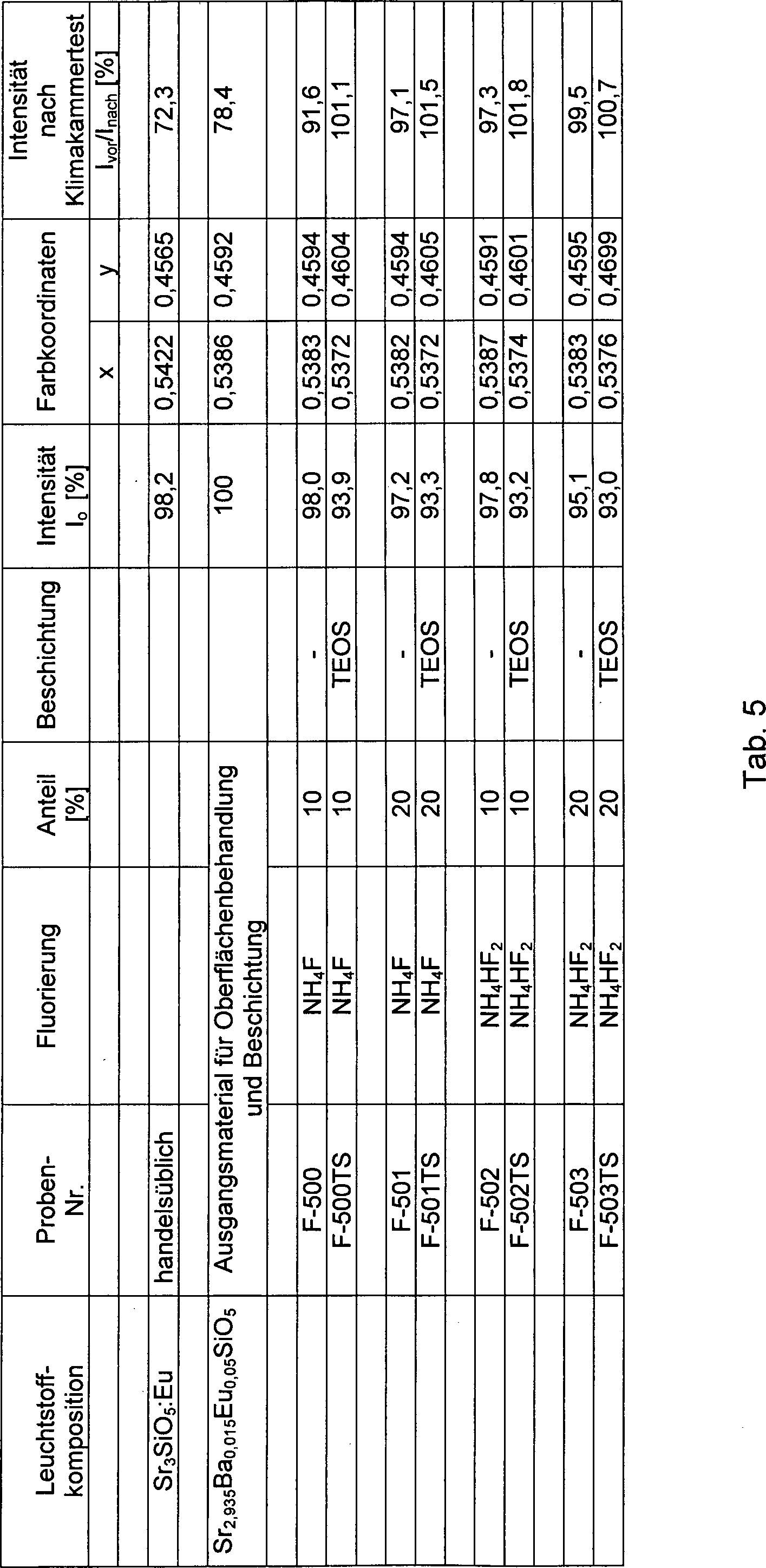
Tab. 5: Optische und Stabilitätsdaten von fluorisierten und von fluorisierten und SiO2-beschichteten, Eu2 +-beschichteten Strontiumoxyorthosilikat-Leuchtstoffen.Tab. 5: Optical and stability data of fluorinated and fluorinated and SiO 2 -coated, Eu + 2 -coated Strontiumoxyorthosilikat phosphors.
Tab. 6: Optische und Stabilitätsdaten von SiO2 beschichteten Strontiumoxyorthosilikat-Leuchtstoffen, die zusätzlich fluorisiert wurden. Tab. 6: Optical and stability data of SiO 2 coated strontium oxyorthosilicate phosphors, which were additionally fluorinated.
Die Synthese der als Grundlage für die Herstellung der erfindungsgemäßen oberflächenmodifizierten Luminophore verwendeten Leuchtstoffpulver erfolgt prinzipiell durch mehrstufige Hochtemperaturfestkörperreaktionen bei Temperaturen oberhalb von 1000°C zwischen den bevorzugt als Ausgangsstoff verwendeten Erdalkalicarbonaten bzw. den entsprechenden Metalloxiden und SiO2, wobei der jeweiligen Reaktionsmischung zur Beförderung der Reaktivität und zur Steuerung der Korngrößenverteilung der resultierenden Luminophore zusätzlich bestimmte Mengen an Schmelzmitteln oder Mineralisierungszusätzen, wie beispielsweise NH4Cl, NH4F oder bestimmte Alkali- bzw. Erdalkalihalogenide bzw. Halogenide der dreiwertigen Metalle hinzugesetzt werden können. In Abhängigkeit von der konkreten Wahl der stöchiometrischen Verhältnisse lassen sich auf diese Weise die gewünschten Kompositionen der dotierten Erdalkalisilikate-Leuchtstoffe, insbesondere auch die der entsprechenden Ortho- und Oxyorthosilikat-Leuchtstoffe, herstellen.The synthesis of the phosphor powder used as a basis for the preparation of the surface-modified luminophores according to the invention is carried out in principle by multi-stage high-temperature solid state reactions at temperatures above 1000 ° C between the alkaline earth metal carbonates preferably used as the starting material or the corresponding metal oxides and SiO 2 , wherein the respective reaction mixture to promote the reactivity and to control the particle size distribution of the resulting luminophores in addition certain amounts of fluxes or mineralization additives, such as NH 4 Cl, NH 4 F or certain alkali or alkaline earth halides or halides of the trivalent metals can be added. Depending on the specific choice of the stoichiometric ratios, the desired compositions of the doped alkaline earth silicate phosphors, in particular those of the corresponding ortho and oxyorthosilicate phosphors, can be produced in this way.
Dazu werden die berechneten Mengen der Ausgangstoffe intensiv vermischt und anschließend einem mehrstündigen Glühprozess im gewünschten Temperaturbereich in einer inerten oder reduzierenden Atmosphäre unterzogen. Dabei kann der Hauptglühprozess zum Zwecke der Optimierung der Leuchtstoffeigenschaften ggf. auch mehrere Glühstufen in unterschiedlichen Temperaturbereichen aufweisen. Nach Beendigung des Glühprozesses werden die Proben auf Raumtemperatur abgekühlt und geeigneten Nachbehandlungsverfahren unterzogen, die beispielsweise auf die Beseitigung von Schmelzmittelresten, auf die Minimierung von Oberflächendefekten oder aber auf die Feineinstellung der Korngrößenverteilung gerichtet sind. Anstelle des Siliziumoxides können alternativ auch Siliziumnitrid (Si3N4) oder aber Silizium haltige Prekursoren unterschiedlicher Zusammensetzung als Reaktanten für die Umsetzung mit den verwendeten Erdalkaliverbindungen eingesetzt werden. Es entspricht dem Wesen der Erfindung, dass die Synthese der für die Herstellung der erfindungsgemäßen Luminophore verwendeten polykristallinen Leuchtstoffpulver nicht auf die beschriebenen Präparationsverfahren beschränkt bleibt.For this purpose, the calculated amounts of the starting materials are thoroughly mixed and then subjected to a multi-hour annealing process in the desired temperature range in an inert or reducing atmosphere. In this case, the main annealing process for the purpose of optimizing the phosphor properties may also have several annealing stages in different temperature ranges. Upon completion of the annealing process, the samples are cooled to room temperature and subjected to appropriate aftertreatment procedures, such as removal of flux residues, minimization of surface defects or fine adjustment of grain size distribution. Instead of the silicon oxide and silicon nitride (Si 3 N 4) or silicon-containing precursors with different compositions can be used as reactants for the reaction with the alkaline earth metal compounds used alternatively. It is in accordance with the essence of the invention that the synthesis of the polycrystalline phosphor powders used for the preparation of the luminophors according to the invention is not limited to the preparation methods described.
Zur erfindungsgemäßen Fluorisierung der Oberflächen der pulverförmigen Erdalkalisilikat-Leuchtstoffe können unterschiedliche anorganische Fluorverbindungen wie Alkalifluoride (z. B. LiF, NaF, KF), Erdalkalifluoride (MgF2, CaF2, SrF2, BaF2), AlF3 und Fluoride der Seltenen Erden (z. B. YF3, LaF3 oder GdF3) NH4F und NH4HF2, sowie weitere anorganische, aber auch organische Fluorverbindungen (z. B. Aminfluoride) eingesetzt werden. Die ausgewählten Materialien werden intensiv mit den silikatischen Leuchtstoffpulvern vermischt, wobei in der Regel wässrige Suspensionen zur Anwendung kommen. Die erforderlichen Mengenanteile der zugesetzten Fluorierungsagenzien hängen von der Löslichkeit der Verbindungen und von den Reaktionsbedingungen (pH-Wert, Temperatur, Intensität des Mischens, Verweilzeit etc.) ab und können leicht experimentell ermittelt werden. Nach Beendigung der Oberflächenbehandlung werden die fluorisierten erfinderischen Leuchtstoffe von der Suspension abgetrennt, gegebenenfalls mit geeigneten Lösungsmitteln gewaschen und anschließend bei Temperaturen zwischen 80 und 200°C getrocknet. Nach dem Abkühlen und Sieben liegen sie in einer anwendungsbereiten Form vor und weisen die erfindungsgemäßen Vorteile auf.For fluorination according to the invention of the surfaces of the pulverulent alkaline earth silicate phosphors, it is possible to use different inorganic fluorine compounds such as alkali fluorides (eg LiF, NaF, KF), alkaline earth fluorides (MgF 2 , CaF 2 , SrF 2 , BaF 2 ), AlF 3 and rare earth fluorides (eg YF 3 , LaF 3 or GdF 3 ) NH 4 F and NH 4 HF 2 , as well as other inorganic, but also organic fluorine compounds (eg amine fluorides). The selected materials are mixed intensively with the siliceous phosphor powders, with aqueous suspensions generally being used. The required proportions of added fluorinating agents depend on the solubility of the compounds and on the reaction conditions (pH, temperature, intensity of mixing, residence time, etc.) and can easily be determined experimentally. After completion of the surface treatment, the fluorinated inventive phosphors are separated from the suspension, optionally washed with suitable solvents and then dried at temperatures between 80 and 200 ° C. After cooling and sieving, they are in an application-ready form and have the advantages according to the invention.
Für die Erzielung optimaler Leuchtstoffeigenschaften kann es in Abhängigkeit von der konkreten Zusammensetzung der erfinderischen Luminophore, von der Art und Menge der verwendeten Fluorierungsagenzien sowie von weiteren Faktoren gegebenenfalls vorteilhaft sein, die erfindungsgemäß hergestellten Leuchtstoffe zusätzlich oder anstelle des Trocknungsprozesses einer thermischen Nachbehandlung (Temperung) im Temperaturbereich von 300 bis 600°C in einer reduzierenden Atmosphäre zu unterziehen.Depending on the specific composition of the inventive luminophores, on the type and amount of fluorination agents used and on other factors, it may be advantageous to obtain the phosphors according to the invention additionally or instead of the drying process of a thermal aftertreatment (tempering) in the temperature range from 300 to 600 ° C in a reducing atmosphere.
Detaillierte Angaben zur Herstellung der erfindungsgemäßen Leuchtstoffe werden im Folgenden anhand mehrerer Ausführungsbeispiele mitgeteilt. AusführungsbeispieleDetailed information on the preparation of the phosphors according to the invention are communicated below with reference to several embodiments. embodiments
Ausführungsbeispiel A1Embodiment A1
Das Ausführungsbeispiel A1 beschreibt die Herstellung des erfinderischen, mit einer fluorhaltigen Oberflächenschicht versehenen Leuchtstoff mit der Grundgitterzusammensetzung Sr2,9Ba0,01Ca0,05SiO5:Eu0,04, der als Probe F-103 mit seinen optischen Daten in Tab. 1 beschrieben und dessen Emissionsspektrum mit Nr.
Ausführungsbeispiel A2Exemplary embodiment A2
Zur Präparation des erfinderischen Leuchtstoffes mit der Probe F-202, die mit ihren optischen Daten in Tab. 2 genannt und deren Emissionsspektrum mit Nr.
Ausführungsbeispiel A3Exemplary embodiment A3
30 g des gemäß Ausführungsbeispiel A2 hergestellten Leuchtstoffes werden in einem Korundtiegel 60 Minuten bei 400°C in einer N2/H2-Atmoshäre, die 35% Wasserstoff enthält, getempert. Nach dem Abkühlen wird die Probe F-202T, die mit ihren optischen Daten in Tab. 2 genannt und deren Emissionsspektrum mit Nr.
Ausführungsbeispiel A4Exemplary embodiment A4
Der Oxyorthosilikat-Leuchtstoff mit der Grundgitterzusammensetzung Sr2,948Ba0,01Cu0,002SiO5:Eu0,04 wird nach seiner gemäß Ausführungsbeispiel A1 erfolgenden Festkörpersynthese zunächst unter Verwendung des Precursormaterials Tetraethoxysilan (TEOS) mit einem SiO2-Netzwerk beschichtet. Dazu werden 50 g des Leuchtstoffes mit 500 ml einer Lösung aus 1 l Ethanol, 18,2 g TEOS und 100 ml 32% Ammoniakwasser vermischt und in einem geeigneten Reaktionsbehälter 2 h lang gerührt. Danach wird der beschichtete Leuchtstoff abgesaugt, mit Ethanol gewaschen und anschließend über 24 h bei 160°C getrocknet.The oxy-orthosilicate phosphor with the basic lattice composition Sr 2,948 Ba 0.01 Cu 0.002 SiO 5 : Eu 0.04 is first coated with a SiO 2 network according to its solid-state synthesis according to Embodiment A1 using the precursor material tetraethoxysilane (TEOS). For this purpose, 50 g of the phosphor are mixed with 500 ml of a solution of 1 l of ethanol, 18.2 g of TEOS and 100 ml of 32% ammonia water and stirred in a suitable reaction vessel for 2 h. Thereafter, the coated phosphor is filtered off, washed with ethanol and then dried at 160 ° C for 24 h.
Im Anschluss an diese vorbereitende Oberflächenbehandlung wird der Luminophor ebenfalls in Analogie zum Ausführungsbeispiel A1 einer Fluorisierung unter Verwendung von NH4F als Fluorierungsagenz unterzogen. Dazu werden 80 g des vorbeschichteten Leuchtstoffes mit 1,98 g NH4F unter den Bedingungen des Ausführungsbeispiel A1 zur Reaktion gebracht. Der so hergestellte erfinderische Leuchtstoff mit der Probe F-TS-600, die mit ihren optischen Daten in Tab. 6 beschrieben und deren Emissionsspektrum mit Nr.
Ausführungsbeispiel B1Exemplary embodiment B1
Für die Herstellung des erfindungsgemäßen Leuchtstoffes mit der Probe F-320 wird ein Grundgitter der Zusammensetzung Sr2,9485Ba0,01Cu0.0015SiO5:Eu0,04 synthetisiert. Dazu werden die stöchiometrischen Mengen SrCO3, BaCO3, CuO, Eu2O3, 65 g SiO2 und 0,3 mol NH4Cl vermischt, in geeignete Glühtiegel gegeben und in einem Hochtemperaturofen für einen Zeitraum von insgesamt 24 h geglüht. Das Glühprogramm weist zwei Hauptglühzonen bei 1200 und 1350°C zu jeweils 3 h auf. Während der ersten Hochtemperaturglühphase wird unter Formiergas mit 5% Wasserstoffkonzentration geglüht und in der anschließenden zweiten Phase die Wasserstoffkonzentration auf 20% erhöht.For the preparation of the phosphor according to the invention with the sample F-320, a base lattice of the composition Sr 2,9485 Ba 0.01 Cu 0.0015 SiO 5 : Eu 0.04 is synthesized. For this purpose, the stoichiometric amounts of SrCO 3 , BaCO 3 , CuO, Eu 2 O 3 , 65 g of SiO 2 and 0.3 mol of NH 4 Cl are mixed, placed in suitable crucible and annealed in a high temperature furnace for a total of 24 h. The annealing program has two main annealing zones at 1200 and 1350 ° C for 3 hours each. During the first Hochtemperaturglühphase is annealed under Formiergas with 5% hydrogen concentration and increased in the subsequent second phase, the hydrogen concentration to 20%.
Nach dem Abkühlen, Waschen und Homogenisieren des Matrixmaterials erfolgt die Fluorisierung der Leuchtstoffoberfläche. Dazu wird als Fluorierungsagenz anstelle des NH4F bzw. des NH4HF2 in dem hier beschriebenen Beispiel Aluminiumfluorid AlF3 verwendet. Zur Wechselwirkung mit der Oberfläche der Leuchtstoffpartikel werden 1,2 g AlF3 bei 60°C in 1 l H2O gegeben und 1 h lang intensiv gerührt. Zu dieser Suspension werden anschließend 100 g der synthetisierten Leuchtstoffmatrix hinzugegeben. Es wird eine Reaktionszeit von 60 Minuten eingehalten. Die Nachbehandlung des beschichteten Leuchtstoffes in Form der Probe F-320 erfolgt in Anlehnung an die Ausführungsbeispiele A1 bis A4. Sie ist mit ihre optischen Daten in Tab. 3 beschrieben und deren Emissionsspektrum in
Ausführungsbeispiel C1 Embodiment C1
Die nachfolgenden Ausführungsbeispiele betreffen erfindungsgemäß beschichtete Erdalkaliorthosilikat-Leuchtstoffe der Zusammensetzung Sr0,876Ba1,024SiO4:Eu0,1. Auch in diesem Fall erfolgt die Herstellung des Basismaterials auf der Grundlage einen Hochtemperaturfestkörperreaktion, wobei das Ansatzgemisch die stöchiometrischen Mengen SrCO3, BaCO3, Eu2O3, SiO2 und 0,2 mol NH4Cl enthält.The following exemplary embodiments relate to alkaline earth orthosilicate phosphors coated according to the invention and of the composition Sr 0.876 Ba 1.024 SiO 4 : Eu 0.1 . Also in this case, the preparation of the base material is based on a high-temperature solid-state reaction wherein the mixture mixture contains the stoichiometric amounts of SrCO 3 , BaCO 3 , Eu 2 O 3 , SiO 2 and 0.2 mol of NH 4 Cl.
Der Glühprozess schließt ein Aufheizen der mit dem Ansatzgemisch befüllten Tiegel auf 1275°C in Stickstoffatmosphäre, das Halten dieser Temperatur über einen Zeitraum von 10 h und das anschließende Abkühlen auf Raumtemperatur ein. Nach dem Erreichen der Hochtemperaturrampe werden dem Schutzgas 20% Wasserstoff beigemischt. Nach dem Abkühlen werden die erhaltenen Materialien zur Entfernung von Schmelzmittelresten einem Waschregime unterzogen, sowie anschließend getrocknet und gesiebt.The annealing process involves heating the pan filled with the batch mixture to 1275 ° C. in a nitrogen atmosphere, maintaining this temperature for a period of 10 hours, and then cooling to room temperature. After reaching the high-temperature ramp, 20% hydrogen is added to the shielding gas. After cooling, the resulting materials are subjected to a washing regime to remove residual flux, followed by drying and sieving.
Für die Fluorisierung des Basismaterials werden 150 g des Leuchtstoffpulvers und 4,268 g NH4F in 3 l H2O suspendiert und anschließend über einen Zeitraum von 2 h gerührt. Nach Beendigung der Beschichtungsprozedur wird der fluorisierte Leuchtstoff mit seiner Probe F-401 abgesaugt, auf der Nutsche mit Ethanol gewaschen und im Trockenschrank über 24 h bei 130°C getrocknet. Die optischen Daten der Probe F-401 werden in Tab. 4 genannt und deren Emissionsspektrum ist mit Nr.
In einem weiteren Schritt kann der erfinderische Leuchtstoff mit seiner Probe F-401 zusätzlich mit einer SiO2-Beschichtung versehen werden. Dazu werden 50 g des fluorisierten Sr0,876Ba1,024SiO4:Eu0,1-Leuchtstoffpulvers in 500 ml TEOS-Lösung, bestehend aus 1 l Ethanol, 25 g TEOS und 150 ml 32% Ammoniakwasser gegeben, die 24 h zuvor angesetzt worden war. Nach einer Rührzeit von 5 h wird die Reaktion beendet. Der oberflächenbeschichtete Leuchtstoff in Form der Probe F-401TS wird abgesaugt, erneut mit Ethanol gewaschen und abschließend getrocknet. Die optischen Daten der Probe F-401TS sind in Tab. 4 genannt. Ihr Emissionsspektrum ist mit Nr.
Die Emissionsspektren der erfindungsgemäßen fluorisierten Leuchtstoffe unterschiedlicher Matrixzusammensetzung im Vergleich zu den jeweils unbehandelten Luminophoren sind in
In den
Vergleichbares gilt für die in der
Zugleich wird aus den in der
Weitere Belege für die Fixierung von feindispersen Fluoriden oder von fluorhaltigen Verbindungen bzw. für die Ausbildung von Netzwerken solcher Verbindungen auf der Oberfläche der erfindungsgemäßen Leuchtstoffe sind in den
Die geringere Intensität des F 1s Peaks der zweiten Probe lässt sich mit einiger Sicherheit dahingehend interpretieren, dass im Ergebnis der Fluorisierung nicht die gesamte Menge des ursprünglich hinzugesetzten Fluors auf der Leuchtstoffoberfläche verbleibt und manifestiert wird. Die signifikante Verschiebung des F 1s Peaks zu niedrigeren Bindungsenergien könnte als ein Indiz für die Ausbildung einer wie auch immer gearteter chemischen Bindung zwischen der applizierten Fluorisierungsagenz und der Oberfläche der Leuchtstoffmatrix gewertet werden.The lower intensity of the
In den Tab. 1 bis Tab. 6 wurden die wichtigsten lumineszenzoptischen Parameter verschiedener erfindungsgemäß konfigurierter silikatischer Leuchtstoffe sowie die Ergebnisse der durchgeführten Stabilitätstests zusammengestellt und mit denen der unveränderten Leuchtstoffpulver sowie in einigen Fällen mit denen handelsüblicher Vergleichsleuchtstoffe verglichen.The most important luminescence-optical parameters of various silicate phosphors configured according to the invention and the results of the stability tests were compiled in Table 1 to Tab. 6 and compared with those of the unchanged phosphor powder and in some cases with those of commercially available comparative phosphors.
Dabei erfolgte die Beurteilung der Feuchtestabilität der Materialien durch siebentägige Lagerung der entsprechenden Leuchtstoffproben in einer Klimakammer, die bei einer Temperatur von 85°C und 85% Luftfeuchte betrieben wurde. Anschließend wurden die Luminophore 24 h lang bei 150°C getrocknet und danach einer vergleichenden Messung der Lumineszenzausbeute unterzogen. Aus den in den Tabellen aufgeführten Daten können zwei wesentliche Schlussfolgerungen gezogen werden:
Zum einen belegen die Resultate der vergleichenden Lumineszenzmessungen die Tatsache, dass sowohl die Lumineszenzeffizienzen der erfinderischen Leuchtstoffe als auch deren Temperaturabhängigkeiten denen handelsüblicher europiumaktivierter Erdalkalioxyorthosilikat- oder entsprechender Orthosilikat-Leuchtstoffe durchaus ebenbürtig sind oder diese sogar übertreffen. Zum anderen zeigen die Ergebnisse der Stabilitätsuntersuchungen, dass die erfinderischen Leuchtstoffe mit manifestierter fluorhaltiger Oberflächenstruktur und ggf. zusätzlicher SiO2-Beschichtung, wie in Tab. 4 bis Tab. 6 dargestellt, im Vergleich zu unveränderten Leuchtstoffen gleicher Matrixzusammensetzung deutlich verbesserte Feuchtigkeitsresistenzen aufweisen.The moisture stability of the materials was assessed by storing the corresponding phosphor samples for seven days in a climatic chamber operated at a temperature of 85 ° C and 85% humidity. Subsequently, the luminophores were dried for 24 hours at 150 ° C and then subjected to a comparative measurement of the luminescence yield. From the data presented in the tables, two main conclusions can be drawn:
On the one hand, the results of the comparative luminescence measurements substantiate the fact that both the luminescence efficiencies of the inventive phosphors and their temperature dependencies are quite equal to or even exceed those of commercially available europium-activated alkaline earth oxyorthosilicate or corresponding orthosilicate phosphors. On the other hand, the results of the stability investigations show that the inventive phosphors with manifested fluorine-containing surface structure and possibly additional SiO 2 coating, as shown in Tab. 4 to Tab. 6, have significantly improved moisture resistance in comparison to unchanged phosphors of the same matrix composition.


ZITATE ENTHALTEN IN DER BESCHREIBUNG QUOTES INCLUDE IN THE DESCRIPTION
Diese Liste der vom Anmelder aufgeführten Dokumente wurde automatisiert erzeugt und ist ausschließlich zur besseren Information des Lesers aufgenommen. Die Liste ist nicht Bestandteil der deutschen Patent- bzw. Gebrauchsmusteranmeldung. Das DPMA übernimmt keinerlei Haftung für etwaige Fehler oder Auslassungen.This list of the documents listed by the applicant has been generated automatically and is included solely for the better information of the reader. The list is not part of the German patent or utility model application. The DPMA assumes no liability for any errors or omissions.
Zitierte PatentliteraturCited patent literature
- US 6489716 B1 [0003] US 6489716 B1 [0003]
- EP 0550937 B1 [0003] EP 0550937 B1 [0003]
- EP 0877070 B1 [0003] EP 0877070 B1 [0003]
Zitierte Nicht-PatentliteraturCited non-patent literature
- Hollemann-Wiberg, Lehrbuch der Anorganischen Chemie, 102. Auflage, Walter de Gruyter & Co., Berlin (2007) [0003] Hollemann-Wiberg, Textbook of Inorganic Chemistry, 102nd Edition, Walter de Gruyter & Co., Berlin (2007) [0003]
- W. M. Yen et al.: Phosphor Handbook, 2nd Ed., CRC Press 2007 [0003] WM Yen et al .: Phosphor Handbook, 2nd ed., CRC Press 2007 [0003]
- Jüstel, T.: Vorlesungskonzept Chemische Materialtechnologie, in: www.tj@fh-muenster.de [0005] Jüstel, T .: Lecture Concept Chemical Material Technology, in: www.tj@fh-muenster.de [0005]
Claims (8)
Priority Applications (24)
| Application Number | Priority Date | Filing Date | Title |
|---|---|---|---|
| DE102010034322A DE102010034322A1 (en) | 2010-08-14 | 2010-08-14 | Surface modified silicate phosphors |
| KR1020100135150A KR101761855B1 (en) | 2010-08-14 | 2010-12-27 | Surface-modified silicate luminophores |
| KR1020100137026A KR101752428B1 (en) | 2010-08-14 | 2010-12-28 | Light emitting device having surface-modified luminophores |
| US13/184,271 US8945421B2 (en) | 2010-08-14 | 2011-07-15 | Surface-modified silicate luminophores |
| RU2013111302/05A RU2013111302A (en) | 2010-08-14 | 2011-07-29 | SURFACE-MODIFIED SILICATE LUMINOPHORS |
| BR112013003416-5A BR112013003416B1 (en) | 2010-08-14 | 2011-07-29 | SILICATE LUMINOPHOR WITH MODIFIED SURFACE |
| JP2013524029A JP2013536283A (en) | 2010-08-14 | 2011-07-29 | Surface-modified silicate phosphor |
| PCT/KR2011/005607 WO2012023714A2 (en) | 2010-08-14 | 2011-07-29 | Surface-modified silicate luminophores |
| EP11818314.4A EP2603571A4 (en) | 2010-08-14 | 2011-07-29 | Surface-modified silicate luminophores |
| CN2011800396821A CN103068953A (en) | 2010-08-14 | 2011-07-29 | Surface-modified silicate luminophores |
| PCT/KR2011/005842 WO2012023737A2 (en) | 2010-08-14 | 2011-08-11 | Light emitting device having surface-modified silicate luminophores |
| RU2013111293/28A RU2569167C2 (en) | 2010-08-14 | 2011-08-11 | Led with silicate luminophors with modified surface |
| JP2013524040A JP2013541828A (en) | 2010-08-14 | 2011-08-11 | Light emitting device having surface-modified silicate illuminant |
| BR112013003417-3A BR112013003417B1 (en) | 2010-08-14 | 2011-08-11 | LIGHT EMITTING DEVICE HAVING SILICATE LUMINOPHORS WITH MODIFIED SURFACE |
| CN201180039661XA CN103081140A (en) | 2010-08-14 | 2011-08-11 | Light emitting device having surface-modified silicate luminophores |
| EP11818337.5A EP2603937B1 (en) | 2010-08-14 | 2011-08-11 | Light emitting device having surface-modified silicate luminophores |
| TW100128948A TWI522444B (en) | 2010-08-14 | 2011-08-12 | Surface-modified silicate luminophores |
| TW100128950A TWI541325B (en) | 2010-08-14 | 2011-08-12 | Light emitting device having surface-modified silicate luminophores |
| US13/209,733 US8581286B2 (en) | 2010-08-14 | 2011-08-15 | Light emitting device having surface-modified silicate luminophores |
| US14/076,642 US9196785B2 (en) | 2010-08-14 | 2013-11-11 | Light emitting device having surface-modified quantum dot luminophores |
| US14/076,738 US9234129B2 (en) | 2010-08-14 | 2013-11-11 | Surface-modified quantum dot luminophores |
| US14/858,641 US9614129B2 (en) | 2010-08-14 | 2015-09-18 | Light emitting device having surface-modified luminophores |
| US15/434,903 US9960324B2 (en) | 2010-08-14 | 2017-02-16 | Light-emitting device having surface-modified luminophores |
| US15/940,926 US10312420B2 (en) | 2010-08-14 | 2018-03-29 | Light-emitting device having surface-modified luminophores |
Applications Claiming Priority (1)
| Application Number | Priority Date | Filing Date | Title |
|---|---|---|---|
| DE102010034322A DE102010034322A1 (en) | 2010-08-14 | 2010-08-14 | Surface modified silicate phosphors |
Publications (1)
| Publication Number | Publication Date |
|---|---|
| DE102010034322A1 true DE102010034322A1 (en) | 2012-02-16 |
Family
ID=45528286
Family Applications (1)
| Application Number | Title | Priority Date | Filing Date |
|---|---|---|---|
| DE102010034322A Withdrawn DE102010034322A1 (en) | 2010-08-14 | 2010-08-14 | Surface modified silicate phosphors |
Country Status (10)
| Country | Link |
|---|---|
| US (2) | US8945421B2 (en) |
| EP (2) | EP2603571A4 (en) |
| JP (2) | JP2013536283A (en) |
| KR (2) | KR101761855B1 (en) |
| CN (2) | CN103068953A (en) |
| BR (2) | BR112013003416B1 (en) |
| DE (1) | DE102010034322A1 (en) |
| RU (2) | RU2013111302A (en) |
| TW (2) | TWI522444B (en) |
| WO (1) | WO2012023714A2 (en) |
Cited By (1)
| Publication number | Priority date | Publication date | Assignee | Title |
|---|---|---|---|---|
| US9865449B2 (en) | 2011-07-29 | 2018-01-09 | Ledvance Gmbh | Illuminant and illuminant lamp comprising said illuminant |
Families Citing this family (21)
| Publication number | Priority date | Publication date | Assignee | Title |
|---|---|---|---|---|
| KR101241650B1 (en) | 2005-10-19 | 2013-03-08 | 엘지이노텍 주식회사 | Package of light emitting diode |
| WO2011038111A1 (en) | 2009-09-23 | 2011-03-31 | Crystalplex Corporation | Passivated nanoparticles |
| US9234129B2 (en) | 2010-08-14 | 2016-01-12 | Seoul Semiconductor Co., Ltd. | Surface-modified quantum dot luminophores |
| DE102010034322A1 (en) * | 2010-08-14 | 2012-02-16 | Litec-Lp Gmbh | Surface modified silicate phosphors |
| US9196785B2 (en) | 2010-08-14 | 2015-11-24 | Seoul Semiconductor Co., Ltd. | Light emitting device having surface-modified quantum dot luminophores |
| US9614129B2 (en) | 2010-08-14 | 2017-04-04 | Seoul Semiconductor Co., Ltd. | Light emitting device having surface-modified luminophores |
| WO2012177761A1 (en) * | 2011-06-20 | 2012-12-27 | Crystalplex Corporation | Stabilized nanocrystals |
| JP2013040236A (en) * | 2011-08-11 | 2013-02-28 | Sekisui Chem Co Ltd | Method for producing surface-treated phosphor and surface-treated phosphor |
| KR101772588B1 (en) * | 2011-08-22 | 2017-09-13 | 한국전자통신연구원 | MIT device molded by Clear compound epoxy and fire detecting device including the MIT device |
| TWI464235B (en) * | 2012-11-21 | 2014-12-11 | Lextar Electronics Corp | Phosphor composition and light emitting diode device using the same |
| JP2016515145A (en) * | 2013-02-25 | 2016-05-26 | コーニンクレッカ フィリップス エヌ ヴェKoninklijke Philips N.V. | Coated luminescent particles, luminescence conversion element, light source, lighting equipment, and method for producing coated luminescent particles |
| DE102013106573B4 (en) * | 2013-06-24 | 2021-12-09 | OSRAM Opto Semiconductors Gesellschaft mit beschränkter Haftung | Radiation-emitting optoelectronic component, gas sensor with radiation-emitting optoelectronic component and method for producing a radiation-emitting optoelectronic component |
| US10995267B2 (en) | 2014-05-29 | 2021-05-04 | Crystalplex Corporation | Dispersion system for quantum dots having organic coatings comprising free polar and non-polar groups |
| US10144815B2 (en) * | 2015-09-29 | 2018-12-04 | Portland State University | Modified nano-clays and coating compositions including the same |
| RU2664143C2 (en) * | 2016-03-21 | 2018-08-15 | Закрытое Акционерное Общество "Научно-производственная фирма "Люминофор" | Method for applying protective film on surface of phosphor dots |
| WO2017201465A1 (en) | 2016-05-19 | 2017-11-23 | Crystalplex Corporation | Cadmium-free quantum dots, tunable quantum dots, quantum dot containing polymer, articles, films, and 3d structure containing them and methods of making and using them |
| CN106316373A (en) * | 2016-07-29 | 2017-01-11 | 江苏罗化新材料有限公司 | Preparing method for high power illuminant fluoride florescent and crystalline ceramics |
| JP6720944B2 (en) | 2017-08-31 | 2020-07-08 | 日亜化学工業株式会社 | Nitride phosphor manufacturing method, nitride phosphor and light emitting device |
| WO2020044439A1 (en) * | 2018-08-28 | 2020-03-05 | シャープ株式会社 | Display device |
| RU202047U1 (en) * | 2020-11-16 | 2021-01-28 | Сергей Григорьевич Никифоров | COMBINED RADIATION SOURCE |
| CN115627161A (en) * | 2022-10-13 | 2023-01-20 | 英特美光电(苏州)有限公司 | Coating method of silicate fluorescent powder |
Citations (3)
| Publication number | Priority date | Publication date | Assignee | Title |
|---|---|---|---|---|
| EP0550937B1 (en) | 1992-01-07 | 1997-03-19 | Koninklijke Philips Electronics N.V. | Low-pressure mercury discharge lamp |
| US6489716B1 (en) | 1998-02-16 | 2002-12-03 | Walter Tews | Compact, energy-saving lamp |
| EP0877070B1 (en) | 1996-01-22 | 2003-05-14 | Kasei Optonix, Ltd. | Photostimulable phosphor |
Family Cites Families (46)
| Publication number | Priority date | Publication date | Assignee | Title |
|---|---|---|---|---|
| JPS5222584A (en) * | 1975-08-14 | 1977-02-19 | Fujitsu Ltd | Method for protective treatment of fluorescent substance |
| JPS52156188A (en) * | 1976-06-21 | 1977-12-26 | Sony Corp | Fluorescent substance |
| JP3234526B2 (en) | 1996-08-29 | 2001-12-04 | 松下電器産業株式会社 | Plasma display panel and method of manufacturing phosphor for plasma display |
| US5792509A (en) * | 1997-02-07 | 1998-08-11 | Industrial Technology Research Institute | Phosphor particle with antireflection coating |
| US6346326B1 (en) | 1998-10-15 | 2002-02-12 | Sarnoff Corporation | Coated moisture impervious red phosphors |
| JP2002069442A (en) | 2000-09-01 | 2002-03-08 | Showa Denko Kk | Silica film coated with light emitting grain |
| AT410266B (en) * | 2000-12-28 | 2003-03-25 | Tridonic Optoelectronics Gmbh | LIGHT SOURCE WITH A LIGHT-EMITTING ELEMENT |
| JP4019649B2 (en) | 2001-04-27 | 2007-12-12 | 日亜化学工業株式会社 | Light emitting device |
| JP2003041247A (en) | 2001-07-31 | 2003-02-13 | Matsushita Electric Ind Co Ltd | Plasma display apparatus |
| CN100423296C (en) | 2001-09-03 | 2008-10-01 | 松下电器产业株式会社 | Semiconductor light-emitting device, light-emitting apparatus and manufacturing method of semiconductor light-emitting device |
| JP4096619B2 (en) * | 2002-05-17 | 2008-06-04 | 松下電器産業株式会社 | Method for manufacturing plasma display device |
| JP4228098B2 (en) * | 2002-08-29 | 2009-02-25 | 東ソー株式会社 | Alkaline earth metal silicate phosphor and light emitting device |
| JP2004168846A (en) | 2002-11-19 | 2004-06-17 | Asahi Glass Co Ltd | Composite particulate and its preparation method |
| US20030173540A1 (en) | 2003-02-19 | 2003-09-18 | Mortz Bradford K | Long persistent phosphor incorporated within a settable material |
| JP2005003436A (en) | 2003-06-10 | 2005-01-06 | Konica Minolta Medical & Graphic Inc | Method for manufacturing stimulable phosphor, radiation image conversion panel using it and method for manufacturing such panel |
| JP4516793B2 (en) * | 2003-08-22 | 2010-08-04 | パナソニック株式会社 | Plasma display panel |
| JP2005068343A (en) * | 2003-08-27 | 2005-03-17 | Nichia Chem Ind Ltd | Vacuum ultraviolet excitation phosphor and plasma display panel |
| JP4322774B2 (en) * | 2003-12-05 | 2009-09-02 | 株式会社東芝 | Phosphor and light emitting device using the same |
| JP4645089B2 (en) | 2004-07-26 | 2011-03-09 | 日亜化学工業株式会社 | Light emitting device and phosphor |
| JP4530755B2 (en) * | 2004-07-28 | 2010-08-25 | 株式会社東京化学研究所 | Orange phosphor |
| US7601276B2 (en) * | 2004-08-04 | 2009-10-13 | Intematix Corporation | Two-phase silicate-based yellow phosphor |
| US20060027785A1 (en) * | 2004-08-04 | 2006-02-09 | Intematix Corporation | Novel silicate-based yellow-green phosphors |
| JP4562453B2 (en) | 2004-08-10 | 2010-10-13 | 富士フイルム株式会社 | Electroluminescent phosphor, method for producing the same, and electroluminescent device |
| EP1794808B1 (en) | 2004-09-10 | 2017-08-09 | Seoul Semiconductor Co., Ltd. | Light emitting diode package having multiple molding resins |
| JP2008523169A (en) * | 2004-12-07 | 2008-07-03 | コーニンクレッカ フィリップス エレクトロニクス エヌ ヴィ | Illumination system including a radiation source and a luminescent material |
| AU2005319965B2 (en) * | 2004-12-22 | 2011-02-10 | Seoul Semiconductor Co., Ltd. | Light emitting device |
| JP2006232949A (en) | 2005-02-23 | 2006-09-07 | Matsushita Electric Works Ltd | Method for treating phosphor particle, light emitting device, and phosphor particle |
| JP2006286672A (en) | 2005-03-31 | 2006-10-19 | Okaya Electric Ind Co Ltd | Light emitting diode and its fabrication process |
| EP2781575A3 (en) | 2005-04-01 | 2015-02-18 | Mitsubishi Chemical Corporation | Alloy powder for inorganic funtional material precursor and phosphor |
| JP5245222B2 (en) * | 2005-08-10 | 2013-07-24 | 三菱化学株式会社 | Phosphor and light emitting device using the same |
| CN101336479A (en) * | 2005-12-01 | 2008-12-31 | 沙诺夫公司 | Phosphors protected against moisture and led lighting devices |
| US20070125984A1 (en) | 2005-12-01 | 2007-06-07 | Sarnoff Corporation | Phosphors protected against moisture and LED lighting devices |
| JP4961828B2 (en) * | 2006-05-12 | 2012-06-27 | ソニー株式会社 | Method for producing nanoparticle-resin composite material |
| JP2009013186A (en) * | 2007-06-29 | 2009-01-22 | Mitsubishi Chemicals Corp | Coated phosphor particles, method for producing coated phosphor particles, phosphor-containing composition, light emitting device, image display device and illuminating device |
| WO2009028818A2 (en) * | 2007-08-28 | 2009-03-05 | Seoul Semiconductor Co., Ltd. | Light emitting device employing non-stoichiometric tetragonal alkaline earth silicate phosphors |
| KR101055769B1 (en) | 2007-08-28 | 2011-08-11 | 서울반도체 주식회사 | Light-emitting device adopting non-stoichiometric tetra-alkaline earth silicate phosphor |
| US7915627B2 (en) | 2007-10-17 | 2011-03-29 | Intematix Corporation | Light emitting device with phosphor wavelength conversion |
| KR20090040097A (en) | 2007-10-19 | 2009-04-23 | 삼성전기주식회사 | Light emitting diode package |
| JP5369295B2 (en) * | 2007-11-08 | 2013-12-18 | 住友金属鉱山株式会社 | Surface-coated strontium silicate phosphor particles, method for producing the same, and light-emitting diode comprising the phosphor particles |
| DE102007056342A1 (en) | 2007-11-22 | 2009-05-28 | Merck Patent Gmbh | Surface modified phosphor particles, useful e.g. for converting blue or near UV lying emission into visible white radiation, comprise luminescent particles containing silicate compounds |
| KR101592836B1 (en) | 2008-02-07 | 2016-02-05 | 미쓰비시 가가꾸 가부시키가이샤 | Semiconductor light emitting device, backlighting device, color image display device and phosphor used for those devices |
| JP4618330B2 (en) * | 2008-05-21 | 2011-01-26 | ソニー株式会社 | Phosphor and its manufacturing method, and light emitting device and display device using phosphor |
| DE102009044255A1 (en) | 2009-10-15 | 2011-04-28 | Leuchtstoffwerk Breitungen Gmbh | Alkaline earth metal silicate phosphors and methods for improving their long-term stability |
| JP2011111506A (en) * | 2009-11-25 | 2011-06-09 | Panasonic Electric Works Co Ltd | Wavelength conversion particle, wavelength conversion member, and light emitting device |
| US20130094186A1 (en) * | 2010-03-31 | 2013-04-18 | Sekisui Chemical Co., Ltd. | Surface-treated fluorescent bodies and process for production of surface-treated fluorescent bodies |
| DE102010034322A1 (en) * | 2010-08-14 | 2012-02-16 | Litec-Lp Gmbh | Surface modified silicate phosphors |
-
2010
- 2010-08-14 DE DE102010034322A patent/DE102010034322A1/en not_active Withdrawn
- 2010-12-27 KR KR1020100135150A patent/KR101761855B1/en active IP Right Grant
- 2010-12-28 KR KR1020100137026A patent/KR101752428B1/en active IP Right Grant
-
2011
- 2011-07-15 US US13/184,271 patent/US8945421B2/en active Active
- 2011-07-29 BR BR112013003416-5A patent/BR112013003416B1/en active IP Right Grant
- 2011-07-29 WO PCT/KR2011/005607 patent/WO2012023714A2/en active Application Filing
- 2011-07-29 RU RU2013111302/05A patent/RU2013111302A/en not_active Application Discontinuation
- 2011-07-29 CN CN2011800396821A patent/CN103068953A/en active Pending
- 2011-07-29 JP JP2013524029A patent/JP2013536283A/en not_active Withdrawn
- 2011-07-29 EP EP11818314.4A patent/EP2603571A4/en not_active Withdrawn
- 2011-08-11 EP EP11818337.5A patent/EP2603937B1/en active Active
- 2011-08-11 BR BR112013003417-3A patent/BR112013003417B1/en active IP Right Grant
- 2011-08-11 CN CN201180039661XA patent/CN103081140A/en active Pending
- 2011-08-11 RU RU2013111293/28A patent/RU2569167C2/en active
- 2011-08-11 JP JP2013524040A patent/JP2013541828A/en active Pending
- 2011-08-12 TW TW100128948A patent/TWI522444B/en not_active IP Right Cessation
- 2011-08-12 TW TW100128950A patent/TWI541325B/en active
- 2011-08-15 US US13/209,733 patent/US8581286B2/en active Active
Patent Citations (3)
| Publication number | Priority date | Publication date | Assignee | Title |
|---|---|---|---|---|
| EP0550937B1 (en) | 1992-01-07 | 1997-03-19 | Koninklijke Philips Electronics N.V. | Low-pressure mercury discharge lamp |
| EP0877070B1 (en) | 1996-01-22 | 2003-05-14 | Kasei Optonix, Ltd. | Photostimulable phosphor |
| US6489716B1 (en) | 1998-02-16 | 2002-12-03 | Walter Tews | Compact, energy-saving lamp |
Non-Patent Citations (3)
| Title |
|---|
| Hollemann-Wiberg, Lehrbuch der Anorganischen Chemie, 102. Auflage, Walter de Gruyter & Co., Berlin (2007) |
| Jüstel, T.: Vorlesungskonzept Chemische Materialtechnologie, in: www.tj@fh-muenster.de |
| W. M. Yen et al.: Phosphor Handbook, 2nd Ed., CRC Press 2007 |
Cited By (1)
| Publication number | Priority date | Publication date | Assignee | Title |
|---|---|---|---|---|
| US9865449B2 (en) | 2011-07-29 | 2018-01-09 | Ledvance Gmbh | Illuminant and illuminant lamp comprising said illuminant |
Also Published As
| Publication number | Publication date |
|---|---|
| BR112013003417B1 (en) | 2021-10-13 |
| EP2603937B1 (en) | 2016-11-23 |
| KR20120023496A (en) | 2012-03-13 |
| US20120205674A1 (en) | 2012-08-16 |
| TW201211208A (en) | 2012-03-16 |
| US20120037850A1 (en) | 2012-02-16 |
| KR101752428B1 (en) | 2017-07-05 |
| BR112013003417A2 (en) | 2020-10-27 |
| KR20120023495A (en) | 2012-03-13 |
| WO2012023714A3 (en) | 2012-05-18 |
| EP2603571A2 (en) | 2013-06-19 |
| BR112013003416A2 (en) | 2020-10-27 |
| US8581286B2 (en) | 2013-11-12 |
| US8945421B2 (en) | 2015-02-03 |
| JP2013541828A (en) | 2013-11-14 |
| EP2603937A4 (en) | 2014-10-22 |
| RU2013111293A (en) | 2014-09-20 |
| RU2013111302A (en) | 2014-09-20 |
| JP2013536283A (en) | 2013-09-19 |
| WO2012023714A2 (en) | 2012-02-23 |
| RU2569167C2 (en) | 2015-11-20 |
| KR101761855B1 (en) | 2017-07-27 |
| TW201211209A (en) | 2012-03-16 |
| CN103068953A (en) | 2013-04-24 |
| TWI522444B (en) | 2016-02-21 |
| TWI541325B (en) | 2016-07-11 |
| EP2603571A4 (en) | 2014-10-22 |
| EP2603937A2 (en) | 2013-06-19 |
| BR112013003416B1 (en) | 2022-01-11 |
| CN103081140A (en) | 2013-05-01 |
Similar Documents
| Publication | Publication Date | Title |
|---|---|---|
| DE102010034322A1 (en) | Surface modified silicate phosphors | |
| DE112014005201B4 (en) | Lighting device and light-emitting diode | |
| DE112005000044B4 (en) | Phosphor, process for its production and its use | |
| EP2324096B1 (en) | Codoped 1-1-2 nitrides | |
| EP1913646A1 (en) | Photonic material with regularly arranged cavities | |
| DE102010045368A1 (en) | Silicophosphate phosphors | |
| EP2528991A1 (en) | Luminescent substances | |
| US9234129B2 (en) | Surface-modified quantum dot luminophores | |
| WO2014094975A1 (en) | Luminescent substances | |
| EP2999767A1 (en) | Phosphors | |
| EP3265537A1 (en) | Fluorescent particles with a protective layer, and method for producing the fluorescent particles with the protective layer | |
| DE102015015355A1 (en) | Mn-activated phosphors | |
| WO2009003971A1 (en) | Manganese-activated metal nitrido-silicate luminescent substance | |
| EP4047072B1 (en) | Light source with luminescent material | |
| DE102009030205A1 (en) | Luminescent substance with europium-doped silicate luminophore, useful in LED, comprises alkaline-, rare-earth metal orthosilicate, and solid solution in form of mixed phases arranged between alkaline- and rare-earth metal oxyorthosilicate | |
| KR101529405B1 (en) | Composition containing a core-shell aluminate, phosphor obtained from said composition, and preparation methods | |
| DE112014006040B4 (en) | Phosphor and light-emitting device | |
| EP3538624A1 (en) | Mn4+-activated luminescence material as conversion luminescent material for led solid state light sources | |
| WO2019053242A1 (en) | Multi-component luminophores as color converters for solid-state light sources | |
| WO2014184003A1 (en) | Method for producing a luminescent material, luminescent material and optoelectronic component | |
| EP3728515B1 (en) | Alkaline earth metal silicate luminophore and method for improving the long-term stability of an alkaline earth metal silicate luminophore | |
| US9758723B2 (en) | Up-conversion phosphor | |
| WO2022200501A1 (en) | Luminous substance, method for the production of a luminous substance and radiation-emitting component |
Legal Events
| Date | Code | Title | Description |
|---|---|---|---|
| R081 | Change of applicant/patentee |
Owner name: SEOUL SEMICONDUCTOR CO., LTD., KR Free format text: FORMER OWNER: LITEC-LP GMBH, 17489 GREIFSWALD, DE Owner name: INTEMATIX-LITEC GMBH, DE Free format text: FORMER OWNER: LITEC-LP GMBH, 17489 GREIFSWALD, DE |
|
| R163 | Identified publications notified |
Effective date: 20120120 |
|
| R082 | Change of representative |
Representative=s name: SCHNICK & GARRELS PATENTANWAELTE, DE Representative=s name: SCHNICK & GARRELS PATENTANWAELTE PARTG MBB, DE |
|
| R081 | Change of applicant/patentee |
Owner name: SEOUL SEMICONDUCTOR CO., LTD., KR Free format text: FORMER OWNERS: LITEC-LP GMBH, 17489 GREIFSWALD, DE; SEOUL SEMICONDUCTOR CO., LTD., SEOUL/SOUL, KR Owner name: INTEMATIX-LITEC GMBH, DE Free format text: FORMER OWNERS: LITEC-LP GMBH, 17489 GREIFSWALD, DE; SEOUL SEMICONDUCTOR CO., LTD., SEOUL/SOUL, KR |
|
| R082 | Change of representative |
Representative=s name: SCHNICK & GARRELS PATENTANWAELTE, DE Representative=s name: SCHNICK & GARRELS PATENTANWAELTE PARTG MBB, DE |
|
| R012 | Request for examination validly filed | ||
| R016 | Response to examination communication | ||
| R119 | Application deemed withdrawn, or ip right lapsed, due to non-payment of renewal fee |