DE102009031978A1 - Device on a card or carding machine for adjusting the working distance between the drum and at least one adjacent roller - Google Patents
Device on a card or carding machine for adjusting the working distance between the drum and at least one adjacent roller Download PDFInfo
- Publication number
- DE102009031978A1 DE102009031978A1 DE102009031978A DE102009031978A DE102009031978A1 DE 102009031978 A1 DE102009031978 A1 DE 102009031978A1 DE 102009031978 A DE102009031978 A DE 102009031978A DE 102009031978 A DE102009031978 A DE 102009031978A DE 102009031978 A1 DE102009031978 A1 DE 102009031978A1
- Authority
- DE
- Germany
- Prior art keywords
- heat energy
- drum
- working distance
- distance
- energy supply
- Prior art date
- Legal status (The legal status is an assumption and is not a legal conclusion. Google has not performed a legal analysis and makes no representation as to the accuracy of the status listed.)
- Withdrawn
Links
- 238000009960 carding Methods 0.000 title claims description 10
- 230000008859 change Effects 0.000 claims abstract description 18
- 239000000835 fiber Substances 0.000 claims abstract description 6
- 230000005540 biological transmission Effects 0.000 claims abstract 2
- 229910052751 metal Inorganic materials 0.000 claims description 21
- 239000002184 metal Substances 0.000 claims description 21
- 238000001816 cooling Methods 0.000 claims description 19
- 238000010438 heat treatment Methods 0.000 claims description 17
- 239000012530 fluid Substances 0.000 claims description 16
- 239000007788 liquid Substances 0.000 claims description 10
- 239000007787 solid Substances 0.000 claims description 10
- 229910052782 aluminium Inorganic materials 0.000 claims description 5
- XAGFODPZIPBFFR-UHFFFAOYSA-N aluminium Chemical compound [Al] XAGFODPZIPBFFR-UHFFFAOYSA-N 0.000 claims description 5
- 238000005096 rolling process Methods 0.000 claims description 5
- 239000000463 material Substances 0.000 claims description 4
- 239000004020 conductor Substances 0.000 claims description 3
- 230000008602 contraction Effects 0.000 claims description 3
- 229910000831 Steel Inorganic materials 0.000 claims description 2
- 239000000853 adhesive Substances 0.000 claims description 2
- 230000001070 adhesive effect Effects 0.000 claims description 2
- 239000010720 hydraulic oil Substances 0.000 claims description 2
- 239000010959 steel Substances 0.000 claims description 2
- 238000012546 transfer Methods 0.000 claims description 2
- 239000003795 chemical substances by application Substances 0.000 claims 4
- 239000003921 oil Substances 0.000 claims 2
- 229910000838 Al alloy Inorganic materials 0.000 claims 1
- 229910000851 Alloy steel Inorganic materials 0.000 claims 1
- 238000004026 adhesive bonding Methods 0.000 claims 1
- 239000011888 foil Substances 0.000 claims 1
- 238000009413 insulation Methods 0.000 claims 1
- 238000005259 measurement Methods 0.000 claims 1
- 230000002441 reversible effect Effects 0.000 claims 1
- 238000006073 displacement reaction Methods 0.000 description 7
- 238000000034 method Methods 0.000 description 6
- 230000008569 process Effects 0.000 description 6
- 230000008901 benefit Effects 0.000 description 4
- 238000000605 extraction Methods 0.000 description 4
- 238000010792 warming Methods 0.000 description 4
- 230000007423 decrease Effects 0.000 description 3
- 238000004519 manufacturing process Methods 0.000 description 3
- RYGMFSIKBFXOCR-UHFFFAOYSA-N Copper Chemical compound [Cu] RYGMFSIKBFXOCR-UHFFFAOYSA-N 0.000 description 2
- 230000033228 biological regulation Effects 0.000 description 2
- 230000006835 compression Effects 0.000 description 2
- 238000007906 compression Methods 0.000 description 2
- 229910052802 copper Inorganic materials 0.000 description 2
- 239000010949 copper Substances 0.000 description 2
- 230000000694 effects Effects 0.000 description 2
- 238000005265 energy consumption Methods 0.000 description 2
- 239000002657 fibrous material Substances 0.000 description 2
- 238000012423 maintenance Methods 0.000 description 2
- 230000002040 relaxant effect Effects 0.000 description 2
- 239000004065 semiconductor Substances 0.000 description 2
- 238000009966 trimming Methods 0.000 description 2
- 238000004804 winding Methods 0.000 description 2
- BUHVIAUBTBOHAG-FOYDDCNASA-N (2r,3r,4s,5r)-2-[6-[[2-(3,5-dimethoxyphenyl)-2-(2-methylphenyl)ethyl]amino]purin-9-yl]-5-(hydroxymethyl)oxolane-3,4-diol Chemical compound COC1=CC(OC)=CC(C(CNC=2C=3N=CN(C=3N=CN=2)[C@H]2[C@@H]([C@H](O)[C@@H](CO)O2)O)C=2C(=CC=CC=2)C)=C1 BUHVIAUBTBOHAG-FOYDDCNASA-N 0.000 description 1
- 206010053567 Coagulopathies Diseases 0.000 description 1
- 229920000742 Cotton Polymers 0.000 description 1
- 230000009471 action Effects 0.000 description 1
- 230000002411 adverse Effects 0.000 description 1
- 239000000919 ceramic Substances 0.000 description 1
- 230000035602 clotting Effects 0.000 description 1
- 230000001143 conditioned effect Effects 0.000 description 1
- 238000010276 construction Methods 0.000 description 1
- 230000003111 delayed effect Effects 0.000 description 1
- 238000013461 design Methods 0.000 description 1
- 238000001514 detection method Methods 0.000 description 1
- 238000011161 development Methods 0.000 description 1
- 230000018109 developmental process Effects 0.000 description 1
- 238000010586 diagram Methods 0.000 description 1
- 238000009826 distribution Methods 0.000 description 1
- 230000005484 gravity Effects 0.000 description 1
- 230000017525 heat dissipation Effects 0.000 description 1
- 230000006872 improvement Effects 0.000 description 1
- 230000002452 interceptive effect Effects 0.000 description 1
- 238000011835 investigation Methods 0.000 description 1
- 238000002955 isolation Methods 0.000 description 1
- 210000000056 organ Anatomy 0.000 description 1
- 230000036316 preload Effects 0.000 description 1
- 238000000746 purification Methods 0.000 description 1
- 230000009467 reduction Effects 0.000 description 1
- 230000001105 regulatory effect Effects 0.000 description 1
- 230000000630 rising effect Effects 0.000 description 1
- 125000006850 spacer group Chemical group 0.000 description 1
- 238000009987 spinning Methods 0.000 description 1
- 239000000126 substance Substances 0.000 description 1
- 239000000725 suspension Substances 0.000 description 1
- 238000012549 training Methods 0.000 description 1
- 230000032258 transport Effects 0.000 description 1
- 238000011144 upstream manufacturing Methods 0.000 description 1
Images


Classifications
-
- D—TEXTILES; PAPER
- D01—NATURAL OR MAN-MADE THREADS OR FIBRES; SPINNING
- D01G—PRELIMINARY TREATMENT OF FIBRES, e.g. FOR SPINNING
- D01G15/00—Carding machines or accessories; Card clothing; Burr-crushing or removing arrangements associated with carding or other preliminary-treatment machines
- D01G15/02—Carding machines
- D01G15/12—Details
- D01G15/28—Supporting arrangements for carding elements; Arrangements for adjusting relative positions of carding elements
Abstract
Bei einer Vorrichtung an einer Karde oder Krempel zur Einstellung des Arbeitsabstandes zwischen der garnierten Trommel und mindestens einer garnierten benachbarten Walze, z. B. Abnehmer und/oder Vorreißer, die mit kleinem gegenseitigem Abstand zwischen den zylindrischen Flächen (Arbeitsabstand) an den Faserübertragungsstellen zusammenwirken und bei der der Arbeitsabstand aufgrund von Dimensionsänderungen durch thermische Dehnungen und/oder Zentrifugalkräfte auf einen vorbestimmten Wert nachstellbar ist, ist eine durch Wärmeenergiezufuhr betätigbare Verstelleinrichtung für die benachbarte Walze vorgesehen. Um auf einfache Weise und in kurzer Zeit bei Dimensionsänderungen der Walzen die Einstellung eines vorbestimmten Abstandes zwischen benachbarten Walzen zu ermöglichen, ist eine Einrichtung zur aktiven Wärmeenergiezu- und/oder -abfuhr vorhanden, die der Verstelleinrichtung zugeordnet ist, wobei bei Dimensionsänderung der Walzen der Arbeitsabstand zwischen der Trommel und mindestens einer benachbarten Walze ein- bzw. nachstellbar ist.In a device on a card or card to adjust the working distance between the garnished drum and at least one garnished adjacent roller, for. B. Customers and / or licker, which cooperate with a small mutual distance between the cylindrical surfaces (working distance) at the fiber transmission points and in which the working distance can be adjusted to a predetermined value due to dimensional changes due to thermal expansion and / or centrifugal forces, is by thermal energy supply actuatable adjustment device provided for the adjacent roller. In order to enable the setting of a predetermined distance between adjacent rolls in a simple manner and in a short time in the event of dimensional changes of the rolls, a device for active heat energy supply and / or removal is provided, which is assigned to the adjusting device, the working distance when the rolls change dimensions is adjustable or adjustable between the drum and at least one adjacent roller.
Description
Die Erfindung betrifft eine Vorrichtung an einer Karde oder Krempel zur Einstellung des Arbeitsabstandes zwischen der garnierten Trommel und mindestens einer garnierten benachbarten Walze, z. B. Abnehmer und/oder Vorreißer, die mit kleinem gegenseitigem Abstand zwischen den zylindrischen Flächen (Arbeitsabstand) an den Faserübertragungsstellen zusammenwirken und bei der der Arbeitsabstand aufgrund von Dimensionsänderungen durch thermische Dehnungen und/oder Zentrifugalkräfte auf einen vorbestimmten Wert nachstellbar ist, wobei eine durch Wärmeenergiezufuhr betätigbare Verstelleinrichtung für die benachbarte Walze vorgesehen ist.The The invention relates to a device on a carding machine or carding machine for adjusting the working distance between the garnished drum and at least one garnished adjacent roll, e.g. B. customers and / or lazies, with a small mutual distance between the cylindrical surfaces (working distance) co-operate the fiber transfer points and in the the working distance due to dimensional changes by thermal strains and / or centrifugal forces on a predetermined value is adjustable, one by heat energy supply actuatable adjusting device for the adjacent Roller is provided.
Beim Kardieren werden zunehmend größere Fasermaterialmengen je Zeiteinheit verarbeitet, was höhere Geschwindigkeiten der Arbeitsorgane und höhere installierte Leistungen bedingt. Steigender Fasermaterialdurchfluss (Produktion) führt schon bei konstant bleibender Arbeitsfläche infolge der mechanischen Arbeit zu erhöhter Erzeugung von Wärme. Zugleich wird aber das technologische Kardierergebnis (Bandgleichmäßigkeit, Reinigungsgrad, Nissenreduzierung usw.) ständig verbessert, was mehr im Kardiereingriff stehende Wirkflächen und engere Einstellungen dieser Wirkflächen z. B. Festdeckel und/oder Wanderdeckel zur Trommel (Tambour) bedingt. Der Anteil zu verarbeitender Chemiefasern, bei denen – im Vergleich zu Baumwolle – im Kontakt mit den Wirkflächen (Garnituren) der Maschine durch Reibung mehr Wärme erzeugt wird, nimmt stetig zu. Die Arbeitsorgane von Hochleistungskarden sind heute allseitig voll gekapselt, um den hohen Sicherheitsstandards zu entsprechen, Partikelemission in die Spinnereiumgebung zu verhindern und den Wartungsbedarf der Maschinen zu minimieren. Roste oder gar offene, materialführende Flächen, die einen Luftaustausch ermöglichen, gehören weitgehend der Vergangenheit an. Durch die genannten Umstände wird der Eintrag von Wärme in die Maschine deutlich gesteigert, während der Wärmeaustrag mittels Konvektion deutlich sinkt. Die dadurch bewirkte stärkere Erwärmung von Hochleistungskarden führt zu größeren thermoelastischen Verformungen, die aufgrund der Ungleichverteilung des Temperaturfeldes die eingestellten Abstände der Wirkflächen beeinflussen: Die Abstände zwischen Trommel und Deckel, Abnehmer, Festdeckeln sowie Ausscheidestellen nehmen ab. Im Extremfall kann der eingestellte Spalt zwischen den Wirkflächen durch Wärmedehnungen vollständig aufgezehrt werden, so dass relativbewegte Bauteile kollidieren. Größere Schäden sind dann an der betroffenen Hochleistungskarde die Folge. Nach alledem kann insbesondere die Erzeugung von Wärme im Arbeitsbereich der Karde zu unterschiedlichen thermischen Dehnungen bei zu großen Temperaturunterschieden zwischen den Bauteilen führen.At the Carding increasingly larger amounts of fiber materials processed per unit of time, resulting in higher speeds working bodies and higher installed services. Rising fiber material flow (production) already leads at a constant working surface due to the mechanical Work to increased production of heat. at the same time but the technological carding result (band uniformity, Degree of purification, reduction of nits etc.), which is more in Kardiereingriff active areas and closer Settings of these effective areas z. B. hard cover and / or Movable lid to drum (drum) conditionally. The share to be processed Man-made fibers containing - in comparison to cotton - im Contact with the active surfaces (sets) of the machine by friction more heat is generated, is steadily increasing. The working organs of high performance cards are today fully enclosed on all sides to to meet the high safety standards, particulate emission to prevent the spinning industry and the need for maintenance of the Minimize machines. Grates or even open, material-leading Areas that allow air exchange, are largely a thing of the past. By the mentioned Circumstances become the entry of heat into the machine significantly increased during the heat release by convection drops significantly. The resulting increased warming of high-performance carards leads to larger ones thermoelastic deformations due to the unequal distribution of the temperature field, the set distances of the active surfaces influence: the distances between drum and lid, Consumers, hard covers and excrement points decrease. In extreme cases can the set gap between the active surfaces through Thermal expansions are completely consumed, so that relatively moving components collide. larger Damage is then to the affected Hochleistungsungskarde the episode. After all, especially the generation of heat in the working area of the card to different thermal expansions if the temperature differences between the components are too great to lead.
Kardierspalte und Walzenabstände sind an der Karde außerordentlich wichtig. Mit einer exakten Einstellung dieser Spalte (Walzenspalte) steht und fällt die Kardierqualität. Unter Wärmeeinfluss dehnen sich die Walzen aus, und die Spalte verändern sich. Zu den Ausdehnungen der Walzen durch Fliehkraft, die die Spalte stark verändern, sorgen hohe Produktion und kardierintensive Chemiefasern zusätzlich für eine starke Erwärmung der Walzen. Es treten thermisch bedingte Dimensionsänderungen der Walzen auf. Um eine optimale Kardierqualität zu erreichen, ist es notwendig, dass die Walzenabstände während des Betriebes konstant bleiben. Konstant heißt in diesem Zusammenhang, dass die Abstandsänderung vorzugsweise weniger als 0,01 mm betragen soll.Kardierspalte and roll distances are extraordinary on the card important. With an exact setting of this column (nips) stands and falls the carding quality. Under the influence of heat The rollers expand and the gaps change. To the expansions of the rollers by centrifugal force, which makes the column strong change, high production and card-intensive Chemical fibers additionally for a strong warming the rollers. There are thermal dimensional changes the rollers on. To achieve optimum carding quality is it is necessary that the roll distances during the Operation remain constant. Constant means in this context, the distance change is preferably less than 0.01 mm should be.
Bei
einer bekannten Vorrichtung (
Der Erfindung liegt demgegenüber die Aufgabe zugrunde, eine Vorrichtung der eingangs beschriebenen Art zu schaffen, die die genannte Nachteile vermeidet, die insbesondere konstruktiv einfach ist und in kurzer Zeit bei Dimensionsänderungen der Walzen die Einstellung eines vorbestimmten Abstandes zwischen benachbarten Walzen ermöglicht.Of the The invention is based on the object, a To provide device of the type described above, which the avoids mentioned disadvantages, which in particular is structurally simple and in a short time with dimensional changes of the rolls the setting of a predetermined distance between adjacent ones Rolling allows.
Die
Lösung dieser Aufgabe erfolgt durch die kennzeichnenden
Merkmale des Anspruchs 1.The
Solution to this problem is done by the characterizing
Features of
Durch die erfindungsgemäßen Maßnahmen gelingt auf einfache Weise eine Konstanthaltung von Walzenabständen in Karden unter Wärmeeinfluss bzw. Fliehkrafteinfluss.By the measures according to the invention succeed in a simple way a constant maintenance of roll distances in cards under the influence of heat or centrifugal force.
Erfindungsgemäß ist eine durch aktive Wärmeenergiezufuhr und -abfuhr betätigbare Verstelleinrichtung für den Abstand zwischen Trommel- und z. B. Abnehmerwalze vorgesehen, um den Abstand bei wechselnden Betriebsbedingungen konstant zu halten. Um die gewünschte Stellbewegung (aktiv regel- und steuerbar) hervorzurufen, wird ein Element für die erforderliche Wärmeenergiezufuhr und -abfuhr verwendet, welches sowohl Kühlen als auch Heizen kann (z. B. ein Peltierelement). Dies ermöglicht eine sehr flexibel und schnell auf Zustandswechsel reagierende Regelung oder Steuerung. Es ist weiterhin möglich, den Kühleffekt durch Kühlkörper, Lüfter oder Ähnlichem zu verstärken.According to the invention an actuatable by active heat energy supply and removal Adjustment device for the distance between drum and z. B. doffer provided to the distance at changing To keep operating conditions constant. To the desired Actuating movement (actively controllable and controllable) will cause a Element for the required heat energy supply and -abfuhr used, which can both cooling and heating (eg a Peltier element). This allows a very flexible and fast state change responsive regulation or control. It is still possible, the cooling effect through Heatsink, fan or similar to reinforce.
Der Sollwert des Verstellweges wird vorzugsweise einer Regelung oder Steuerung vorgegeben. Durch eine aktive Regelung wird es möglich, die durch die Fliehkraft erzeugte Abstandsänderung auszugleichen. Ein passives Verstellsystem würde erst zeitverzögert auf die Abstandsänderung reagieren, da die Abstandsänderung durch die Fliehkraft viel schneller herbei geführt wird, als eine Änderung durch Wärmeenergiezufuhr.Of the Setpoint of the adjustment is preferably a control or Control specified. Active regulation makes it possible compensate for the change in distance generated by the centrifugal force. A passive adjustment system would be delayed respond to the distance change, since the distance change caused by the centrifugal force much faster, as a change by heat energy supply.
Bevorzugt wird bei Anlauf- und Auslaufphasen der Maschine das Stellelement der Versteileinrichtung zur größten Ausdehnung gebracht und der Abnehmer näher an die Trommel gefahren. Mit steigender Drehzahl und Zunahme der Wärme wird die Temperatur der Verstelleinrichtung wieder erniedrigt, um die Abstandsveränderung durch Zunahme der Fliehkraft und der Walzentemperaturen auszugleichen. Demnach ist es bei warm gewordener Maschine gar nicht mehr oder nur wenig nötig zu heizen oder zu kühlen, wenn die Maschine zuvor so voreingestellt wurde, dass der Abstand bei warmer Maschine auf Raumtemperatur ideal ist. Ggf. auszugleichen sind dann nur noch die Schwankungen der Umgebungstemperatur bzw. Anpassungen aufgrund einer veränderten Materialauswahl. Die vorliegende Erfindung arbeitet dadurch ressourcenschonend, was den Energieverbrauch anbelangt.Prefers During start-up and shut-down phases of the machine, the actuating element becomes the adjustment device to the largest extent brought and the customer moved closer to the drum. As the speed increases and the heat increases, so does the temperature the adjustment again lowered to the distance change compensate for by increasing the centrifugal force and the rolling temperatures. Accordingly, it is no longer when the machine has become warm or little need to heat or cool if the machine was previously preset so that the distance at warm machine at room temperature is ideal. Possibly. are to be compensated then only the fluctuations of the ambient temperature or adjustments due to a changed material selection. The present This invention works resource-saving, which reduces energy consumption As.
Ein weiterer Vorteil besteht in der Verbesserung der Maschinensicherheit. Gibt es zum Beispiel einen plötzlichen Maschinen-Stopp (z. B. durch Stromausfall) und die Wärmeelemente fallen aus, verringern sich die Abstände zwischen Trommel und den umliegenden Walzen, da die Verstelleinheit aufgrund ihrer weitaus geringeren Masse schneller abkühlen kann, als die Trommel. Dies kann zu Berührungen zwischen Tambour und den umliegenden Walzen und Arbeitselementen führen. In der vorliegenden Erfindung wird der Abstand in derartigen Notfällen vergrößert.One Another advantage is the improvement of machine safety. Is there, for example, a sudden machine stop (eg due to power failure) and the heating elements fall The distances between the drum and the drum are reduced surrounding rollers, because the adjustment unit due to their far lower mass can cool faster than the drum. This can cause contact between the drum and the surrounding rollers and work items. In the present invention the distance is increased in such emergencies.
Die Vorteile der Erfindung sind unter anderem:
- • Die Verstelleinrichtung kann neben dem Heizen auch gekühlt werden und ist dadurch flexibler und schneller regel- und steuerbar.
- • Die entgegengesetzte Wirkrichtung der Verstellelemente senkt den Energieverbrauch und bietet eine Sicherheit vor Maschinenschäden bei plötzlichen Maschinen-Stopps.
- • In addition to heating, the adjusting device can also be cooled, making it more flexible and faster to control and control.
- • The opposite effective direction of the adjustment elements reduces energy consumption and provides protection against machine damage in the event of sudden machine stops.
Mit der erfindungsgemäßen Vorrichtung (Aktor) werden Abstände von Walzen automatisch eingestellt. Mit dieser Einstellbarkeit werden Spaltänderungen durch die Fliehkraft der Trommel und die Wärmeausdehnung der Walzen mittels einer Regelstruktur ausgeglichen. Es ist eine aktive Aufheizung und eine aktive Kühlung ermöglicht, d. h. es werden in kurzer Zeit gezielt bestimmte Temperaturen der Verstelleinrichtung verwirklicht. Insbesondere erlaubt die Erfindung – außer der aktiven Aufheizung – auch eine aktive Kühlung (Wärmeabfuhr bzw. Wärmeenergieentzug) der Verstelleinrichtung. Die Einrichtung, die sowohl Kühlen als auch Heizen kann, ermöglicht eine sehr flexibel und schnell auf Zustandswechsel reagierende Regelung oder Steuerung.With the device according to the invention (actuator) distances of rollers are set automatically. With this adjustability, gap changes due to the centrifugal force of the drum and the thermal expansion of the rolls are compensated by means of a control structure. It is an active heating and active cooling allows, ie it will be realized in a short time specifically certain temperatures of the adjustment. In particular, the invention allows - in addition to the active heating - also an active cooling (heat dissipation or heat energy removal) of the adjustment. The device, which can both cool and heat, allows a very flexible and fast to state change responsive control or control.
Die
Ansprüche 2 bis 77 haben vorteilhafte Weiterbildungen der
Erfindung zum Inhalt.The
Die Erfindung wird nachfolgend anhand von zeichnerisch dargestellten Ausführungsbeispielen näher erläutert.The Invention will be described below with reference to the drawings Embodiments explained in more detail.
Es zeigt:It shows:
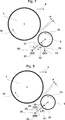
Nach
Entsprechend
Das
Stellelement
Sind
nach
Um
den Körper des Stellelements
Dank
der großen Oberfläche des Kühlkörpers
Durch
die Verwendung des Peltierelements
Nach
Das
Peltierelement
Der
Sollwert des Arbeitsabstandes wird vorgegeben durch die Berechnungen
aus Trommeldrehzahl und den Temperaturen von Trommel
Durch
geschickte Anordnung eines Stellelements
Der
Abnehmer
Da
das Peltierelement
Die
Ausbildungen nach den
Nach
Nach
Die
Temperatur nimmt von dem Niveau Walzen über die Seitenschilder
bis zum Maschinengestell ab. Erfindungsgemäß wird
gezielt und mit geringer Wärmeleistung bzw. Kühlung
eine Kompensation der Dimensionsänderungen der Walzen realisiert. Das
Maschinengestell
Die
(nicht dargestellte) Arbeitsbreite der Trommel
Durch
die erfindungsgemäßen Maßnahmen, d. h.
aktive Wärmezuführung und aktiver Wärmeentzug
an den Stellelementen für die der Trommel
Um
in Notsituation eine sehr schnelle Abkühlung des Stellelements
ZITATE ENTHALTEN IN DER BESCHREIBUNGQUOTES INCLUDE IN THE DESCRIPTION
Diese Liste der vom Anmelder aufgeführten Dokumente wurde automatisiert erzeugt und ist ausschließlich zur besseren Information des Lesers aufgenommen. Die Liste ist nicht Bestandteil der deutschen Patent- bzw. Gebrauchsmusteranmeldung. Das DPMA übernimmt keinerlei Haftung für etwaige Fehler oder Auslassungen.This list The documents listed by the applicant have been automated generated and is solely for better information recorded by the reader. The list is not part of the German Patent or utility model application. The DPMA takes over no liability for any errors or omissions.
Zitierte PatentliteraturCited patent literature
- - DE 2948825 [0004] - DE 2948825 [0004]
Claims (77)
Priority Applications (5)
| Application Number | Priority Date | Filing Date | Title |
|---|---|---|---|
| DE102009031978A DE102009031978A1 (en) | 2009-07-06 | 2009-07-06 | Device on a card or carding machine for adjusting the working distance between the drum and at least one adjacent roller |
| CH01061/10A CH701398B1 (en) | 2009-07-06 | 2010-06-29 | Device on a card or card to adjust the working distance between the garnished drum and at least one garnished adjacent roller. |
| ITMI2010A001216A IT1401104B1 (en) | 2009-07-06 | 2010-07-02 | EQUIPMENT ON A CARDA WITH A HATS OR A ROLLER CARDA FOR SETTING THE WORKING DISTANCE BETWEEN THE CYLINDER AND AT LEAST ONE ROLLER NEARBY |
| GB201011158A GB2471755B (en) | 2009-07-06 | 2010-07-02 | Apparatus on a flat card or roller card for setting the working spacing between the cylinder and at least one neighbouring roller |
| CN201010224313.7A CN101942714B (en) | 2009-07-06 | 2010-07-06 | Apparatus on a flat card or roller card for setting the working spacing between the cylinder and one neighbouring roller |
Applications Claiming Priority (1)
| Application Number | Priority Date | Filing Date | Title |
|---|---|---|---|
| DE102009031978A DE102009031978A1 (en) | 2009-07-06 | 2009-07-06 | Device on a card or carding machine for adjusting the working distance between the drum and at least one adjacent roller |
Publications (1)
| Publication Number | Publication Date |
|---|---|
| DE102009031978A1 true DE102009031978A1 (en) | 2011-01-13 |
Family
ID=42669095
Family Applications (1)
| Application Number | Title | Priority Date | Filing Date |
|---|---|---|---|
| DE102009031978A Withdrawn DE102009031978A1 (en) | 2009-07-06 | 2009-07-06 | Device on a card or carding machine for adjusting the working distance between the drum and at least one adjacent roller |
Country Status (5)
| Country | Link |
|---|---|
| CN (1) | CN101942714B (en) |
| CH (1) | CH701398B1 (en) |
| DE (1) | DE102009031978A1 (en) |
| GB (1) | GB2471755B (en) |
| IT (1) | IT1401104B1 (en) |
Cited By (4)
| Publication number | Priority date | Publication date | Assignee | Title |
|---|---|---|---|---|
| DE102011113390A1 (en) * | 2011-09-16 | 2013-03-21 | Trützschler GmbH & Co Kommanditgesellschaft | Device on a card or card with a garnished drum and at least one garnished adjacent customer |
| CH712271A1 (en) * | 2016-03-17 | 2017-09-29 | Rieter Ag Maschf | Work item. |
| DE102016117872A1 (en) | 2016-09-22 | 2018-03-22 | TRüTZSCHLER GMBH & CO. KG | teasel |
| EP3530779A1 (en) | 2018-02-23 | 2019-08-28 | Trützschler GmbH & Co. KG | Device and method for adjusting a distance between a drum and at least one adjacent work element in a spinning preparation machine |
Families Citing this family (4)
| Publication number | Priority date | Publication date | Assignee | Title |
|---|---|---|---|---|
| DE102010018840A1 (en) * | 2010-04-29 | 2011-11-03 | TRüTZSCHLER GMBH & CO. KG | Device on a card or card with a garnished drum and at least one adjacent roller |
| CH713459A1 (en) * | 2017-02-15 | 2018-08-15 | Rieter Ag Maschf | Method for operating a card and card. |
| DE102017117661A1 (en) * | 2017-08-03 | 2019-02-07 | TRüTZSCHLER GMBH & CO. KG | Flat bar system |
| CN109137151A (en) * | 2018-08-21 | 2019-01-04 | 安徽世倾环保科技有限公司 | A kind of production equipment for deduster filtrate |
Citations (5)
| Publication number | Priority date | Publication date | Assignee | Title |
|---|---|---|---|---|
| DE2948825C2 (en) | 1978-04-25 | 1989-08-17 | Maschinenfabrik Rieter Ag, Winterthur, Ch | |
| EP1231303A1 (en) * | 2001-02-12 | 2002-08-14 | Maschinenfabrik Rieter Ag | Adjusting device and process for the carding clearance in a carding machine with flats |
| DE10305048A1 (en) * | 2003-02-07 | 2004-08-19 | Trützschler GmbH & Co KG | Device on a card for adjusting the working distance between the drum and at least one adjacent roller |
| DE102005052142A1 (en) * | 2005-10-28 | 2007-05-03 | TRüTZSCHLER GMBH & CO. KG | Adjuster for gap between cylinder clothing and fiber working elements on a card uses thermal expansion of hydraulic oil to control movement |
| DE102006014419A1 (en) * | 2006-03-27 | 2007-10-04 | TRüTZSCHLER GMBH & CO. KG | Device on a spinning preparation machine, in particular carding, carding o. The like., For adjusting the Kardierabstandes |
Family Cites Families (1)
| Publication number | Priority date | Publication date | Assignee | Title |
|---|---|---|---|---|
| DE10325273A1 (en) * | 2003-06-03 | 2004-12-23 | Maschinenfabrik Rieter Ag | Adaptation of the card elements to thermal expansion effects |
-
2009
- 2009-07-06 DE DE102009031978A patent/DE102009031978A1/en not_active Withdrawn
-
2010
- 2010-06-29 CH CH01061/10A patent/CH701398B1/en not_active IP Right Cessation
- 2010-07-02 GB GB201011158A patent/GB2471755B/en not_active Expired - Fee Related
- 2010-07-02 IT ITMI2010A001216A patent/IT1401104B1/en active
- 2010-07-06 CN CN201010224313.7A patent/CN101942714B/en active Active
Patent Citations (5)
| Publication number | Priority date | Publication date | Assignee | Title |
|---|---|---|---|---|
| DE2948825C2 (en) | 1978-04-25 | 1989-08-17 | Maschinenfabrik Rieter Ag, Winterthur, Ch | |
| EP1231303A1 (en) * | 2001-02-12 | 2002-08-14 | Maschinenfabrik Rieter Ag | Adjusting device and process for the carding clearance in a carding machine with flats |
| DE10305048A1 (en) * | 2003-02-07 | 2004-08-19 | Trützschler GmbH & Co KG | Device on a card for adjusting the working distance between the drum and at least one adjacent roller |
| DE102005052142A1 (en) * | 2005-10-28 | 2007-05-03 | TRüTZSCHLER GMBH & CO. KG | Adjuster for gap between cylinder clothing and fiber working elements on a card uses thermal expansion of hydraulic oil to control movement |
| DE102006014419A1 (en) * | 2006-03-27 | 2007-10-04 | TRüTZSCHLER GMBH & CO. KG | Device on a spinning preparation machine, in particular carding, carding o. The like., For adjusting the Kardierabstandes |
Cited By (8)
| Publication number | Priority date | Publication date | Assignee | Title |
|---|---|---|---|---|
| DE102011113390A1 (en) * | 2011-09-16 | 2013-03-21 | Trützschler GmbH & Co Kommanditgesellschaft | Device on a card or card with a garnished drum and at least one garnished adjacent customer |
| CH712271A1 (en) * | 2016-03-17 | 2017-09-29 | Rieter Ag Maschf | Work item. |
| CN108884601A (en) * | 2016-03-17 | 2018-11-23 | 里特机械公司 | Operation element |
| CN108884601B (en) * | 2016-03-17 | 2021-06-29 | 里特机械公司 | Working element |
| DE102016117872A1 (en) | 2016-09-22 | 2018-03-22 | TRüTZSCHLER GMBH & CO. KG | teasel |
| EP3530779A1 (en) | 2018-02-23 | 2019-08-28 | Trützschler GmbH & Co. KG | Device and method for adjusting a distance between a drum and at least one adjacent work element in a spinning preparation machine |
| CN110184692A (en) * | 2018-02-23 | 2019-08-30 | 特吕茨施勒有限及两合公司 | Adjusted in spinning preparation machine the workplace between cylinder and at least one operated adjacent element away from device and method |
| CN110184692B (en) * | 2018-02-23 | 2022-03-11 | 特吕茨施勒有限及两合公司 | Device and method for adjusting the working distance between a cylinder and at least one adjacent working element in a spinning preparation machine |
Also Published As
| Publication number | Publication date |
|---|---|
| CN101942714B (en) | 2014-12-24 |
| IT1401104B1 (en) | 2013-07-12 |
| GB2471755A (en) | 2011-01-12 |
| CH701398A2 (en) | 2011-01-14 |
| CN101942714A (en) | 2011-01-12 |
| CH701398B1 (en) | 2014-06-30 |
| GB2471755B (en) | 2012-11-21 |
| GB201011158D0 (en) | 2010-08-18 |
| ITMI20101216A1 (en) | 2011-01-07 |
Similar Documents
| Publication | Publication Date | Title |
|---|---|---|
| DE102009031978A1 (en) | Device on a card or carding machine for adjusting the working distance between the drum and at least one adjacent roller | |
| DE102009031979A1 (en) | Device on a card or card with a drum, working elements and adjustable holding elements | |
| DE3305429C2 (en) | Calender for pressure and heat treatment of webs | |
| DE102005052142B4 (en) | Device on a card with a drum, carding elements and adjustable holding elements | |
| DE102005038401B4 (en) | Device on a spinning preparation machine, in particular a card, card or the like, with a roller, for. B. drum, which has a cylindrical, garnished outer surface | |
| EP1652975B1 (en) | Spinning preparation machine as well as a housing for a drafting device in a spinning preparation machine | |
| EP1798011A1 (en) | Rotary cutter | |
| DE4202917C1 (en) | ||
| DE10106315A1 (en) | Method for operating a card and a card | |
| DE10305048B4 (en) | Device on a carding machine for adjusting the working distance between the drum and at least one adjacent roller | |
| DE102005005222B4 (en) | Device on a spinning preparation machine, in particular carding machine, carding o. The like., In which a garnished roller opposite a machine element | |
| DE102013105628A1 (en) | Furnace muffle for an annealing furnace | |
| EP3530779B1 (en) | Device and method for adjusting a distance between a drum and at least one adjacent work element in a spinning preparation machine | |
| DE102011006357A1 (en) | Rolling mill for producing a metal strip and method for producing a rolling mill | |
| WO1999054072A1 (en) | Method and device for continuously casting thin metal strips | |
| CH703066B1 (en) | Card with a garnish drum and at least one adjacent roller. | |
| DE2524018C3 (en) | Continuous ironing and embossing machine for leather or the like | |
| EP0140196A2 (en) | Calandar | |
| DE102005047432A1 (en) | Plate glass heat treatment oven has ceramic rollers and comparative heat sensors | |
| AT14312U1 (en) | Device for cooling moving flat material | |
| AT14313U1 (en) | Device for cooling moving flat material | |
| EP2586911A1 (en) | Web treatment device | |
| DE1461242C (en) | Device for maintaining and adjusting the knife clearance in a cutting tool | |
| DE1461242B (en) | Device for maintaining and adjusting the knife clearance in a cutting tool | |
| DE2509391A1 (en) | Multiroll calendar with individual roll temperature control - plus adjustment of roll nip daylight in groups |
Legal Events
| Date | Code | Title | Description |
|---|---|---|---|
| OM8 | Search report available as to paragraph 43 lit. 1 sentence 1 patent law | ||
| R012 | Request for examination validly filed | ||
| R081 | Change of applicant/patentee |
Owner name: TRUETZSCHLER GROUP SE, DE Free format text: FORMER OWNER: TRUETZSCHLER GMBH & CO KOMMANDITGESELLSCHAFT, 41199 MOENCHENGLADBACH, DE |
|
| R119 | Application deemed withdrawn, or ip right lapsed, due to non-payment of renewal fee |