CN87105404A - Excavating machine for driving mining of mine - Google Patents
Excavating machine for driving mining of mine Download PDFInfo
- Publication number
- CN87105404A CN87105404A CN198787105404A CN87105404A CN87105404A CN 87105404 A CN87105404 A CN 87105404A CN 198787105404 A CN198787105404 A CN 198787105404A CN 87105404 A CN87105404 A CN 87105404A CN 87105404 A CN87105404 A CN 87105404A
- Authority
- CN
- China
- Prior art keywords
- cutting arm
- crushing device
- swinging axle
- digger
- bulk
- Prior art date
- Legal status (The legal status is an assumption and is not a legal conclusion. Google has not performed a legal analysis and makes no representation as to the accuracy of the status listed.)
- Pending
Links
Images

Classifications
-
- E—FIXED CONSTRUCTIONS
- E21—EARTH DRILLING; MINING
- E21D—SHAFTS; TUNNELS; GALLERIES; LARGE UNDERGROUND CHAMBERS
- E21D9/00—Tunnels or galleries, with or without linings; Methods or apparatus for making thereof; Layout of tunnels or galleries
- E21D9/10—Making by using boring or cutting machines
- E21D9/106—Making by using boring or cutting machines with percussive tools, e.g. pick-hammers
-
- E—FIXED CONSTRUCTIONS
- E21—EARTH DRILLING; MINING
- E21C—MINING OR QUARRYING
- E21C27/00—Machines which completely free the mineral from the seam
- E21C27/20—Mineral freed by means not involving slitting
- E21C27/28—Mineral freed by means not involving slitting by percussive drills with breaking-down means, e.g. wedge-shaped tools
-
- E—FIXED CONSTRUCTIONS
- E21—EARTH DRILLING; MINING
- E21D—SHAFTS; TUNNELS; GALLERIES; LARGE UNDERGROUND CHAMBERS
- E21D9/00—Tunnels or galleries, with or without linings; Methods or apparatus for making thereof; Layout of tunnels or galleries
- E21D9/10—Making by using boring or cutting machines
- E21D9/1006—Making by using boring or cutting machines with rotary cutting tools
- E21D9/1013—Making by using boring or cutting machines with rotary cutting tools on a tool-carrier supported by a movable boom
- E21D9/102—Making by using boring or cutting machines with rotary cutting tools on a tool-carrier supported by a movable boom by a longitudinally extending boom being pivotable about a vertical and a transverse axis
- E21D9/1026—Making by using boring or cutting machines with rotary cutting tools on a tool-carrier supported by a movable boom by a longitudinally extending boom being pivotable about a vertical and a transverse axis the tool-carrier being rotated about a transverse axis
-
- E—FIXED CONSTRUCTIONS
- E21—EARTH DRILLING; MINING
- E21D—SHAFTS; TUNNELS; GALLERIES; LARGE UNDERGROUND CHAMBERS
- E21D9/00—Tunnels or galleries, with or without linings; Methods or apparatus for making thereof; Layout of tunnels or galleries
- E21D9/12—Devices for removing or hauling away excavated material or spoil; Working or loading platforms
- E21D9/126—Loading devices or installations
-
- B—PERFORMING OPERATIONS; TRANSPORTING
- B25—HAND TOOLS; PORTABLE POWER-DRIVEN TOOLS; MANIPULATORS
- B25D—PERCUSSIVE TOOLS
- B25D2250/00—General details of portable percussive tools; Components used in portable percussive tools
- B25D2250/275—Tools having at least two similar components
- B25D2250/285—Tools having three or more similar components, e.g. three motors
- B25D2250/291—Tools having three or more parallel bits, e.g. needle guns
Abstract
Mining excavation or exploitation digger.This digger (2) has a frame type walking car (3,4), and the cutting arm (23) of a band cutterhead (28) is housed in the mule carriage of being expert at, and cutting arm (23) both can rise or descend again around a swinging axle (22) swing around first swinging axle (24).Being equipped with one in the bottom (30) of cutting arm (23) can be around second swinging axle (32) rising and the bulk crushing device (31) that descends.Destroyer (44) can stretch out in the guide housings (42) of bulk breaker (31) with hydraulic impact hammer (43), and arrives on the direction of the large rock mass (16) for the treatment of fragmentation on the loading stage (9) that is positioned at digger (2).
Description
The present invention relates to mining excavation or exploitation digger.
Above-mentioned digger has a cutting arm that is arranged on above the table frame formula walking, this cutting arm both can be around a vertical pendulum moving axis swing, can raise or reduction around the first horizontal pendulum moving axis again, its free end is installed with a cutterhead, being equipped with one on the cutting arm can raise with respect to cutting arm or reduce around second swinging axle, has a loading stage that is positioned at frame type walking car front portion, loading bin and one with the mechanism of wheel loaders of the bulk crushing device digger that impacts mode work and passes the ore conveyer that frame type walking car reaches the back.
In a kind of known such digger (see Germany open patent specification No. 2304021), there is a hydraulic hammer to be arranged on the cantilever of cutting arm, and can rises and descend round second swinging axle.This hydraulic hammer can be swung between resting position above the cutting arm and operating position at one, and when being in the operating position, the boring by percussion instrument of hydraulic hammer can exceed cutterhead on tunneling direction.Utilize this hydraulic hammer can those are too hard, cutterhead can't cut broken horsestone and smash at work plane.But this hydraulic hammer should and can't not be used to smash yet.But this hydraulic hammer should and can't not be used to smash large rock mass or the ore of falling on the loading stage of cutting arm below yet.
In tunneling process, produce and fall large rock mass or the ore that is bulk or sheet through regular meeting, and the loader mechanism of digger can't be handled it.Operating personnel must leave the frame that is usually located at digger top and sail platform, with pneumatic hammer bulk are smashed.Observation by in practice shows, thisly stops the digger operation, and the practice of broken bulk can cause 20 to 25% production time loss by hand.
A kind of equipment of clearing up peace leveling bottom surface, lane is disclosed in No. 8230528.5 utility model patent manual in Germany.This equipment has a scraper bowl that is driven by the surge device, a loading stage and a conveyer.A cantilever that can rise, descend and swing is housed in the side of this equipment.Have one on the cantilever and be positioned at dress and plant the platform front, can act on cleaning and/or developing device on the gallery bottom surface.The front hierarchal arrangement of this device some jump bits.But these jump bits can not be used for the bulk on the broken loading platform.
Task of the present invention is, falls when large rock mass or ore and loads when going up, and the loss of production time is restricted to minimum degree.
Feature of the present invention is: second swinging axle is fixed on the bottom of cutting arm, makes the bulk crushing device to reach to be positioned on the loading stage everywhere large rock mass or ore, and in case of necessity can also be by means of the one-movement-freedom-degree of cutting arm with its fragmentation.Each jump bit of bulk crushing device for example can be electronic or pneumatic, but preferably drive by fluid power.Each pneumatic or hydraulic impact hammer for example can be made of impactor and jump bit footstalk, impactor links to each other with working piston, the jump bit footstalk then is positioned at pilot sleeve, can be reciprocating under the driving of working piston, and impactor and pilot sleeve all are positioned at a jump bit housing.Second swinging axle preferably is horizontal.In driving and recovery process, if having the rock of bulk or ore to fall on the loading stage, operating personnel no longer need to leave it in the ordinary course of things and are positioned at bridge above the digger.He only need adjust the bulk crushing device with respect to the position of cutting arm, regulate the freedom of motion of cutting arm in case of necessity again, just can be in the shortest time smash, make the rock or the ore that are broken into fritter to be transferred away from rock or the ore that be about to be positioned on the loading stage largest block everywhere.So just can accomplish through restarting the cut driving after shut-down operation of short duration, the broken bulk as early as possible.The safety of operation also can be improved, because operating personnel are keeping enough distances when fragmentation and between the fracture area.Before broken bulk, cutting arm can be placed on the crushing stroke position of a level for example, make tup unlikely loader mechanism or other parts of running into digger in shattering process of jump bit.
On the bulk crushing device, constitute a destroyer side by side and abreast by jump bit, the bulk crushing device can be made simple and compact structure, and has various desirable broken power.
The bulk crushing device can lean against the bottom of cutting arm and obtain favorable protection on its resting position, exempt from the bump of the ore that falls, and also can not produce any restriction to the degree of freedom of cutting arm in this external cut tunneling process.
Have at least a jump bit or destroyer in the side guide of bulk crushing device, to move axially on the bulk crushing device, can make the sphere of action of bulk crushing device obtain enlarging.In addition, whole breaker can also be under the situation of mobile cutting arm not moves on in simple mode and treats fragmentation or fragmented rock or ore place.
Feeding piston one cylinder unit that is parallel to guide rail is equipped with in the both sides of at least one jump bit of digger or destroyer, one end of this unit is hinged on and is near the affiliated guide rail of second swinging axle, the other end of this unit is hinged on the outer end away from the housing of at least one jump bit of second swinging axle or destroyer, and this structure can realize above-mentioned relative motion by simple and effective way.The feeding piston-cylinder-unit is hydraulic pressure preferably.
The guide rail of digger is an ingredient of guide housings, guide housings is fixed on the swinging axle that can drive, this swinging axle and second swinging axle are in coaxial position, and be rotary type and be fixed on the cutting arm, this just provides a kind of and has helped promoting and the structural concept of the bulk crushing device that descends.The driving of swinging axle for example can realize by a hydraulic pressure lift piston-cylinder-unit that is fixed on the rod member on the swinging axle and is hinged on this rod member.
If operating personnel can not observe the loading stage zone that is positioned at below the cutting arm on the bridge of large-scale digger, then can a console be set and remedy by side, the place ahead at frame type walking car.The driver or second operator may stand in the next door of digger, control and the fragmentation of supervision large rock mass on loading stage.Another selection is that operating personnel can carry and handle a what is called that is separated with machine " chest is carried the formula control cabinet on the arm ", i.e. a remote control instrument.This person both can be the driver of machine, also can be second operator.
Below the contrast accompanying drawing in given example the present invention is further illustrated.Wherein:
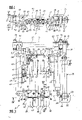
Fig. 1 represents a lateral view with digger of bulk crushing device,
Fig. 2 represents the top view of digger shown in Figure 1, and cutting arm wherein has been flapped toward a side,
The partial enlarged drawing at III place in Fig. 3 presentation graphs 2, what wherein show is the bulk crushing device,
In Fig. 4 presentation graphs 3 along the view that IV-the IV line is done, but the jump bit that do not draw,
In Fig. 5 presentation graphs 4 along the view that V-the V line is done,
In Fig. 6 presentation graphs 3 along the cutaway view Amplified image that VI-the VI line is done,
In Fig. 7 presentation graphs 3 along cutaway view Amplified image that VII-the VII line is done.
In Fig. 1, the digger 2 that is arranged in gallery 1 has a crawler-type traveling car 3 and a framework 4.Framework 4 is supported on by hydraulic leg 5 on the bottom surface 6 of gallery 1 (referring to shown in Figure 2).Also can load onto this hydraulic leg in the front portion of digger 2 in case of necessity.
An articulated loading stage 9 that stretches to work plane 8 on the prolongation 7 in framework 4 the place aheads, by the effect of lift cylinder 10, this loading stage can rise or descend around a horizontal pendulum moving axis 11.Loading stage 9 is ingredients of ore loader mechanism 12, below in conjunction with Fig. 2 it is described in detail.
Also articulated one can center on the baffle plate 14 that horizontal pendulum moving axis 13 rises and descends on framework 4, and the free end of this baffle plate front portion rides on the support 15 of loading stage 9.The part of baffle plate 14 shows with chain-dotted line in Fig. 2.This baffle plate is one to be made by steel plate, and leading edge is the flat board of circular shape, and its effect is to prevent that the rock of bulk or ore from entering the transport tube 17 that is positioned at digger 2 middle parts.Because the leading edge of baffle plate 14 freely rides on the support 15, so it can be along with all risings and the descending motion of loader mechanism are moved together.
On framework 4, supporting one by a spherical bearing rotating disk 20 can be around the swing platform 21 of vertical pendulum moving axis 22 swings.An articulated cutting arm 23 on swing platform 21, it can rise or descend around the first horizontal pendulum moving axis 24 under the effect of lift cylinder 25, lift cylinder 25 is positioned at the both sides of cutting arm 23, and an end is hinged on the cutting arm 23, and the other end is hinged on the flange 26 of swing platform 21.Adorning a gear-box 27 on the cutting arm 23, and a cutterhead 28 is being housed at front end.Cutting arm 23 is to realize by the oscillating cylinder 29 that is contained in both sides around the swing of swinging axle 22.One end of this oscillating cylinder is hinged on the framework 4, and the other end is hinged on the rear portion of swing platform 21.
Be provided with a bulk crushing device 31 in the bottom 30 of cutting arm 23, this device can raise or reduction around the second horizontal pendulum moving axis 32.Bulk crushing device 31 is fixed on the swinging axle 33, and upward this root rod member can be by jigger lifting piston-cylinder unit 35 drivings that are hinged on cutting arm 23 front portions to also have a rod member 34 to be fixed on this in addition.
In the cutting arm 23 on the top of bulk crushing device 31 a cut motor 30 is housed, this motor is by electric installation 37 power supplies that are located on the framework 34.
When bulk crushing device 31 was in resting position, its fragmentation cell 35 was positioned at the bottom 30 of cutting arm 23.In whole cut process, bulk crushing device 31 remains on this resting position always; That is to say that as long as cutterhead 28 is positioned at work plane 8 places, the bulk crushing device is not just worked.When a too big rock or ore were excavated or fall, operating personnel can or be positioned on the console 39 of framework 4 sides earlier cutting arm 23 by the horizontal level that is positioned at large rock mass or ore 16 tops that moves on to shown in Figure 1 from the bridge above the framework 4 38.The resting position that bulk crushing device 31 is marked with chain-dotted line in Fig. 1 is set out and is swung an angle 40 then, and this angle is 90 ° in this example, up to being in vertical state fully as shown in Figure 1.If bulk 16 is on the position that is not on the loading stage as shown in Figure 1, but be in lean on very much after, for example directly lean against the forward position of baffle plate 14, then only need bulk crushing device 31 set out from its resting position and correspondingly swing a less angle 40 and get final product the position that the example chain-dotted line that is positioned at the right side is as shown in FIG. 1 represented.If bulk 16 be not be in lean on after, but be on the very forward position on the loading stage 9, then should allow bulk crushing device 31 after swinging to angle 40, continue angle 41 of swing again, this angle is 30 ° in this example.Left side extreme position shown in Fig. 1 also draws with chain-dotted line.Because bulk crushing device 31 can raise and reduce by the way, in case of necessity also can be round swinging axle 22 swing cutting arms 23, can accomplish in fact that therefore any point on loading stage carries out fragmentation to the bulk above dropping on 16.
A guide housings 42 is arranged on the bulk crushing device 31, the destroyer 44 that is made of four jump bits 43 has been installed in this housing, this destroyer can move in the axial direction.This moving is to realize that under the effect of the feeding piston-cylinder-unit 45 that is arranged on destroyer 44 both sides an end of this unit is hinged on the guide housings 42, and the other end is hinged on the side flanges 46(of destroyer 44 referring to Fig. 3) on.By this layout destroyer 44 and guide housings 42 are relatively moved, up to move to one be suitable for the operating position of broken bulk 16 most till, in this moving process, do not need to make whole cutting arm 23 to rise or descend round first swinging axle 24.
All above-mentioned functions not only can be handled on bridge 38, but also can handle on the console 39 that is positioned at the side.
Be installed in the Motor Drive one row hydraulic pump 48 at digger 2 rear portions, the required power of each hydraulic operation mechanism is supplied with by these hydraulic pumps.Being positioned at chain-linked conveyer 18(and seeing Fig. 2) motor of both sides 49 driving shaft 50 that drives chain-linked conveyers 18 rear portions rotates.
If bulk crushing device 31 is smashed the rock or the ore 16 of bulk on request, then the muck clitter can be delivered to the rear with normal method by digger 2 with loader mechanism 12.Destroyer 44 comes back in the guide housings 42, and 31 in whole bulk crushing device rises again to be got back among Fig. 1 with the represented resting position that goes out of chain-dotted line.At this moment just can restart cutterhead 28 beginning diggings.
On the destroyer 44 dress jump bit 43 can more than or be less than four.Under extreme case even a jump bit 43 also can be installed, promptly replace whole destroyer 44 with this jump bit.
In Fig. 2, loader mechanism 12 has a loading bin 51 that is " rake pawl " shape that is set on above the loading stage 9, and this mechanism itself has been known, therefore repeats no more.Broken ore or bulk 16(that loading bin 51 will drop on above the loading stage 9 see Fig. 1) hold together to chain-linked conveyer 18.Chain-linked conveyer utilized its transverse baffle 52 that ore is passed the conveying letter 17 that is positioned on the digger 2 behind the last ore in 18 years and carries out.
What Fig. 3 was extremely shown in Figure 5 is bulk crushing device 31 view in different directions.
In Fig. 3, the two ends of swinging axle 33 are installed in the bearing 54, and can rotate; Bearing 54 is fixed on the bottom surface 30 of cutting arm 23 by screw 53.Rod member 34 is fixed on the swinging axle 33 by flat key 55, can not relatively rotate between the two.Articulated jigger lifting piston-the cylinder unit 35 of the other end of this rod member, the other end of this unit 35 then are hinged on the junction plate 56 that is positioned on cutting arm 23 bottom surfaces 30.
In like manner, the guide rail 58 that is positioned at an other side also welds together with a side direction boss 61, and this boss is fixed on above the swinging axle 33 by closing sleeve 62, thereby can't rotate.Articulated another is positioned at the end of the feeding piston-cylinder-unit 45 of the same side on boss 59.
A firm junction plate 63 also has been installed on the guide housings 42, and this junction plate is fixed by bolt 64 earlier, so that guide rail 57,58 is adjusted, and then welds together with guide rail 57,58.This method of attachment is used in the left side of the junction plate 63 shown in Fig. 3, and the right side of junction plate 63 is then dead with guide rail 58 welderings at the very start.As shown in Figure 3, after 45 withdrawals of feeding piston-cylinder-unit, junction plate 63 can get up whole destroyer 44 protection basically.
In Fig. 3, side direction boss 46 rigidity on the lower end of gib block 66 and the destroyer 44 weld together.
In Fig. 3, the fastening block 80 of a horizontally set is equipped with in the bottom of shell 67, has the hole 81 that is parallel to each other above it, and the free end 82(that these holes are used for the shell 83 of fastening destroyer 43 sees Fig. 6).A fastening sleeve 84 all has been installed in each free end 82, and has been seen Fig. 4 by four bolt 85() fastening sleeve is fixed on the fastening block 80.All be pressed into a pilot sleeve 86 that the nitrile copper becomes in each fastening sleeve 84, this is because this part belongs to part easy to wear, need change.The footstalk 87 of a steel has been installed in pilot sleeve 86 vertically, and this footstalk and the profile of destroyer 43 are that the jump bit 88 of chisel shape is connected.
According to shown in Figure 3, the heavy spacer pin 90(that the side of every footstalk 87 all has 89, one of one groove millings to be positioned at fastening block 80 sees Fig. 7) pass this groove milling.Every heavy spacer pin 90 is all fixing by safetybolt 91.This structure can prevent that footstalk 87 from dropping out when freely moving axially in the sleeve 86 that leads in pilot sleeve 86, particularly when bulk crushing device 31 during to lower swing.In addition, the acting in conjunction by groove milling 89 and heavy spacer pin 90 can also prevent that the footstalk 87 of jump bit 88 from rotating around its longitudinal axis.Because jump bit 88 does not possess the symmetrical structure of revolving, therefore this anti-reinsurance is necessary.
According to shown in Figure 6, hydraulic impactor 92 is housed in housing 83.In Fig. 3, can see the rear end 76 of the hydraulic impactor 92 that be arranged in parallel.Each hydraulic impactor 92 all is supported on the affiliated fixed muffle 84 by disk spring 93 with its housing.When footstalk moved inward in the process of broken large rock mass or ore (see figure 6), the working piston 94 of impactor 92 just can impinge upon the inner of footstalk 87.On figure, do not show though be positioned at a kind of of impactor 92, belonged to the idle running impact that known controller can prevent to stretch into because of footstalk 87 the not enough working piston 94 that causes of stroke in the impactor 92.When jump bit 88 is overhang, but when treating that broken bulk 16 contact, the idle running impact can not take place yet.
In Fig. 7, safetybolt 91 and nut 95 thereof respectively are screwed in together by a pad 96 and 97, and this pad is positioned on the convex shoulder 98 and 99 of through hole 100 of fastening block 80, and heavy alignment pin 90 then is installed in the through hole 100.
Claims (7)
1, mining excavation or exploitation digger 2, have one and be arranged on table frame formula walking car (3,4) Shang Mian cutting arm (23), this cutting arm both can be around a vertical pendulum moving axis (22) swing, can raise and reduction around the first horizontal pendulum moving axis (24) again, its free end is installed with a cutterhead (28), being equipped with one on the cutting arm (23) can be around the bulk crushing device (31) with impact mode work of second swinging axle (32) with respect to cutting arm (23) rising or reduction, the loader mechanism (12) of digger (2) has one and is positioned at frame type walking car (3,4) Qian Bu loading stage (9), a loading bin (51) and one pass frame type walking car (3,4), reach the ore conveyer (18) of back, feature of the present invention is, second swinging axle (32) is fixed on the bottom of cutting arm (23), make the bulk crushing device to reach to be positioned on the loading stage (9) everywhere large rock mass or ore (16), and with its fragmentation, in case of necessity can also be by means of the one-movement-freedom-degree of cutting arm (23).
2, digger according to claim 1 is characterized in that, on bulk crushing device (31), constitutes a destroyer (44) side by side and abreast by jump bit (43).
According to claim 1 or 2 described diggers, it is characterized in that 3, bulk crushing device (31) leans against the bottom (30) of cutting arm (23) on resting position.
4, according to claim 2 or 3 described diggers, it is characterized in that having at least a jump bit (43) or destroyer (44) in the side guide (57,58) of bulk crushing device (31), to move axially on the bulk crushing device (31).
5, digger according to claim 4, it is characterized in that, be equipped with in the both sides of at least one jump bit (43) or destroyer (44) and be parallel to guide rail (57,58) feeding piston-cylinder-unit (45), one end of this feeding piston-cylinder-unit (45) is hinged on and is near the affiliated guide rail (57 of second swinging axle (32), 58) on, the other end of this feeding piston-cylinder-unit (45) then is hinged on away from second swinging axle (32), the outer end of the housing (67) of at least one jump bit or destroyer (44).
6, according to claim 4 or 5 described diggers, it is characterized in that, guide rail (57,58) be an ingredient of guide housings (42), guide housings is fixed on the swinging axle that can drive (33), this swinging axle and second swinging axle (32) are in coaxial position, and are rotary type and are fixed on the cutting arm (23).
7, according to any one described digger among the claim 1 to 6, it is characterized in that, be provided with a console (39), be used to control the function of cutting arm (23) and bulk crushing device (31) in the side, the place ahead of frame type walking car (3,4).
Applications Claiming Priority (2)
| Application Number | Priority Date | Filing Date | Title |
|---|---|---|---|
| DEP3626986.7 | 1986-08-08 | ||
| DE19863626986 DE3626986A1 (en) | 1986-08-08 | 1986-08-08 | MOUNTAIN PITCHING OR EXTRACTING CUTTING MACHINE |
Publications (1)
| Publication Number | Publication Date |
|---|---|
| CN87105404A true CN87105404A (en) | 1988-02-17 |
Family
ID=6307007
Family Applications (1)
| Application Number | Title | Priority Date | Filing Date |
|---|---|---|---|
| CN198787105404A Pending CN87105404A (en) | 1986-08-08 | 1987-08-07 | Excavating machine for driving mining of mine |
Country Status (3)
| Country | Link |
|---|---|
| CN (1) | CN87105404A (en) |
| DE (1) | DE3626986A1 (en) |
| FR (1) | FR2602542B1 (en) |
Cited By (4)
| Publication number | Priority date | Publication date | Assignee | Title |
|---|---|---|---|---|
| CN102787550A (en) * | 2012-08-16 | 2012-11-21 | 浙江大学 | Breaking hammer with auxiliary stone breaking device |
| WO2013033979A2 (en) * | 2011-09-11 | 2013-03-14 | Liu Suhua | Rolling friction impact digging method and rolling friction impact digging machine using said method |
| WO2013123828A1 (en) * | 2012-02-24 | 2013-08-29 | Liu Suhua | Rolling friction or suspension friction impact mining method and wear-resistant impact mining machine using said method |
| WO2014023085A1 (en) * | 2012-08-06 | 2014-02-13 | Liu Suhua | Multi-point guidance support method for reciprocating impact machine and reciprocating impact machine device having multi-point guidance support that implements said method |
Families Citing this family (5)
| Publication number | Priority date | Publication date | Assignee | Title |
|---|---|---|---|---|
| CN101881162B (en) * | 2009-05-06 | 2012-10-03 | 三一重型装备有限公司 | Drill loader |
| EP2821590A1 (en) * | 2013-07-04 | 2015-01-07 | Sandvik Intellectual Property AB | Mining machine gathering head |
| CN104074523A (en) * | 2014-06-16 | 2014-10-01 | 郑有山 | Improvement of hydraulic impact hammer cantilever structure of downhole development machine |
| CA2960064C (en) * | 2014-10-06 | 2022-08-16 | Sandvik Intellectual Property Ab | Cutting apparatus |
| CN106194171B (en) * | 2016-08-11 | 2018-04-03 | 安徽宏昌机电装备制造有限公司 | A kind of adaptivity digging all-in-one |
Family Cites Families (3)
| Publication number | Priority date | Publication date | Assignee | Title |
|---|---|---|---|---|
| FR2194849B1 (en) * | 1972-08-01 | 1976-10-29 | Guibbert Jean | |
| FR2420642A1 (en) * | 1978-03-24 | 1979-10-19 | Borie Entr Travaux Publics And | Repair wagon for railway tunnels - has pneumatic pick on adjustable telescopic arm to cut out sections of lining to be replaced |
| DE8230528U1 (en) * | 1982-10-30 | 1983-02-03 | Rudolf Hausherr & Söhne GmbH & Co KG, 4322 Sprockhövel | Device for carrying out cleaning and leveling work in underground routes |
-
1986
- 1986-08-08 DE DE19863626986 patent/DE3626986A1/en active Granted
-
1987
- 1987-06-10 FR FR8708049A patent/FR2602542B1/en not_active Expired - Fee Related
- 1987-08-07 CN CN198787105404A patent/CN87105404A/en active Pending
Cited By (10)
| Publication number | Priority date | Publication date | Assignee | Title |
|---|---|---|---|---|
| WO2013033979A2 (en) * | 2011-09-11 | 2013-03-14 | Liu Suhua | Rolling friction impact digging method and rolling friction impact digging machine using said method |
| WO2013033979A3 (en) * | 2011-09-11 | 2013-05-02 | Liu Suhua | Rolling friction impact digging method and rolling friction impact digging machine using said method |
| WO2013123828A1 (en) * | 2012-02-24 | 2013-08-29 | Liu Suhua | Rolling friction or suspension friction impact mining method and wear-resistant impact mining machine using said method |
| CN103291291A (en) * | 2012-02-24 | 2013-09-11 | 刘素华 | Rolling friction or suspension friction impact excavating method and antiabrasion impact excavator for implementing the same |
| CN103291291B (en) * | 2012-02-24 | 2015-02-18 | 刘素华 | Rolling friction or suspension friction impact excavating method and antiabrasion impact excavator for implementing the same |
| EA026928B1 (en) * | 2012-02-24 | 2017-05-31 | Сухуа Лю | Mining machine with an easily detachable cutting head |
| WO2014023085A1 (en) * | 2012-08-06 | 2014-02-13 | Liu Suhua | Multi-point guidance support method for reciprocating impact machine and reciprocating impact machine device having multi-point guidance support that implements said method |
| AU2013302125B2 (en) * | 2012-08-06 | 2017-02-23 | Suhua LIU | Method for guiding and multipoint supporting reciprocating impacter and device for implementing method for guiding and multipoint supporting reciprocating impacter |
| CN102787550A (en) * | 2012-08-16 | 2012-11-21 | 浙江大学 | Breaking hammer with auxiliary stone breaking device |
| CN102787550B (en) * | 2012-08-16 | 2015-01-21 | 浙江大学 | Breaking hammer with auxiliary stone breaking device |
Also Published As
| Publication number | Publication date |
|---|---|
| DE3626986C2 (en) | 1990-09-20 |
| FR2602542A1 (en) | 1988-02-12 |
| DE3626986A1 (en) | 1988-03-10 |
| FR2602542B1 (en) | 1991-10-31 |
Similar Documents
| Publication | Publication Date | Title |
|---|---|---|
| EP1642650B1 (en) | Mobile crushing apparatus | |
| CN87105404A (en) | Excavating machine for driving mining of mine | |
| CN105714865B (en) | A kind of colliery roadway repairer | |
| CN112412490A (en) | Hard rock tunneling machine | |
| US4884848A (en) | Device and method for exploiting material | |
| CN210003277U (en) | tunnel working device with jumbolter at tail | |
| CN110219590A (en) | A kind of multifunctional drill and engineering equipment | |
| CN105386760B (en) | Hydraulic control is taken a step quartering hammer digger | |
| CN206280076U (en) | Development machine and driving system | |
| CN211115983U (en) | Movable type is taken off dress and is broken fortune all-in-one | |
| CN112796358A (en) | Underground mining prying scraper and mining method thereof | |
| CA2515076C (en) | Scaling assembly | |
| CN112746841A (en) | Multi-stage rocker arm multi-cutting drum coal mining machine | |
| CN205089317U (en) | Quartering hammer digger of taking a step is controlled to liquid | |
| CN2793327Y (en) | Manless coal cutter under well | |
| CN209723079U (en) | A kind of sled hair excavates and loads all-in-one machine | |
| CN218376463U (en) | Coal mine bottom pulling equipment | |
| CN215398615U (en) | Front frame mechanism of movable crushing trolley | |
| CN103089260A (en) | Pounding and shoveling coal cutter crushing mechanism | |
| CN219587506U (en) | Novel have reverse circulation rig for waste stone clearance | |
| CN220579829U (en) | Bridge demolishs equipment | |
| CN213743422U (en) | Hard rock tunneling machine | |
| CN216791010U (en) | Rock matter side slope blasting is with filling out medicine device | |
| CN216741495U (en) | Novel underground continuous coal mining equipment | |
| RU2014452C1 (en) | Stone-splitting machine |
Legal Events
| Date | Code | Title | Description |
|---|---|---|---|
| C06 | Publication | ||
| PB01 | Publication | ||
| WD01 | Invention patent application deemed withdrawn after publication |