CN2786439Y - Reciprocating grate type coal-coal gas integrated boiler - Google Patents
Reciprocating grate type coal-coal gas integrated boiler Download PDFInfo
- Publication number
- CN2786439Y CN2786439Y CNU2005200202527U CN200520020252U CN2786439Y CN 2786439 Y CN2786439 Y CN 2786439Y CN U2005200202527 U CNU2005200202527 U CN U2005200202527U CN 200520020252 U CN200520020252 U CN 200520020252U CN 2786439 Y CN2786439 Y CN 2786439Y
- Authority
- CN
- China
- Prior art keywords
- chamber
- collection case
- boiler
- screen tube
- water screen
- Prior art date
- Legal status (The legal status is an assumption and is not a legal conclusion. Google has not performed a legal analysis and makes no representation as to the accuracy of the status listed.)
- Expired - Fee Related
Links
Images
Landscapes
- Solid-Fuel Combustion (AREA)
Abstract
The utility model relates to a reciprocating grate type coal-coal gas integrated boiler, which belongs to the technical field of boiler making. The reciprocating grate type coal-coal gas integrated boiler is provided for solving the problems that fuels of an industrial boiler are insufficiently combusted, the heat efficiency is low, the smoke exhaust can not reach an environmental protection standard, a grate is long and the metal consumption is big. A fuel firing system is composed of a reciprocating pushing grate, a gas generating chamber, a main combustion chamber, an after combustion chamber, a convection heat radiating zone and a boiler body, and an actuating medium water circulating system is composed of an upper boiler barrel, a lower boiler barrel, an upper transverse header, a side header, a convection bank, a water return pipe, a water outlet pipe, an upper header and a lower transverse header. The utility model is the industrial boiler with small capacity, and can be widely applied. The utility model has the advantages that the heat efficiency can reach 78 percents, smoke exhaust can reach the environmental protection standard, the structure is compact, the grate is short and the metal consumption is low.
Description
Technical field: the utility model relates to a kind of reciprocal grate formula coal-coal gas integrated boiler, belongs to boiler manufacturing technology field.
Background technology: at present in the middle samll cities and towns of China, the low capacity Industrial Boiler still is widely used, in low capacity Industrial Boiler field, traditional combustion system is a layer combustion, combustion apparatus mainly contains traveling-grate stoker and reciprocating grate, the characteristics of this fire grate are to burn to be divided into preheating section, main combustion section and after-flame section three parts along the length of fire grate, its shortcoming is that fuel combustion is insufficient, it is low that ubiquity the thermal efficiency, unburnt heat loss is generally about 12%, smoke evacuation does not reach environmental protection standard, and fire grate is longer, and the consumption of metal is big.
Summary of the invention: design a kind of reciprocal grate formula coal-coal gas integrated boiler for solving the problem that the fuel combustion of low capacity Industrial Boiler is insufficient, the thermal efficiency is low, smoke evacuation does not reach environmental protection standard, the longer metal wastage of fire grate is big, the utility model is formed fuel combustion system by reciprocating grate, gas generating chamber, main combustion chamber, secondary furnace, advection heat radiation area, boiler body; Form the working-medium water circulatory system by upper drum, lower drum, last horizontal collection case, side collection case, convection bank, return pipe, outlet pipe, water screen tube 12,17,28,29, upper collecting chamber, following horizontal collection case; In fuel combustion system: the gas generating chamber bottom is a reciprocating grate, fire grate segment is made by heat-resisting alloy steel, anterior is the insulation furnace wall, both sides are the furnace wall that lays water screen tube 12, the rear portion partition wall of rear portion for being formed by the refractory concrete ramming is provided with water screen tube 17 in the partition wall of rear portion, top is provided with gas exit, the bottom is provided with fuel outlet, and top is the furnace roof wall that lays water screen tube 29; The bottom of main combustion chamber, both sides and top are consistent with the structure of gas generating chamber, the front portion of main combustion chamber is the rear portion partition wall of gas generating chamber, the partition wall of the rear portion of main combustion chamber for being formed by the refractory concrete ramming is provided with water screen tube 28 in the partition wall, the bottom is provided with the lime-ash outlet; The bottom of secondary furnace, both sides and top are consistent with the structure of gas generating chamber, oblique brick baffle and the perpendicular brick baffle of the rear portion of secondary furnace for forming by the refractory concrete ramming, and the centre of perpendicular brick baffle has outlet flue and communicates with the advection heat radiation chamber; There is upper drum the top of advection heat radiation chamber, and there is lower drum the below, and convection bank is installed on every side, and the smoke shelf plate is installed in the advection heat radiation chamber; In the working-medium water circulatory system: the upper end of upper drum and upper collecting chamber, outlet pipe, return pipe, convection bank links, the lower end and the lower drum of convection bank link, the upper and lower side of water screen tube 12 links with upper collecting chamber and side collection case respectively, the upper and lower side of water screen tube 17 and water screen tube 28 connects with last horizontal collection case and following horizontal collection case respectively, water screen tube 29 connects with upper collecting chamber, go up horizontal collection case and connect with upper collecting chamber, following horizontal collection case connects with side collection case; Coal bunker is installed in the front upper place of anterior insulation furnace wall, and the below of coal bunker communicates with gas generating chamber, and flue outlet is positioned at the top of back furnace wall and heat-insulation layer; Reciprocal grate formula coal-coal gas integrated boiler can be used as the low capacity Industrial Boiler and uses.
The beneficial effects of the utility model, advantage and characteristics:
1, changed traditional combustion system, it is more abundant to burn: the combustion system that the utility model has adopted grate firing to combine with the chamber combustion, combustion apparatus comprises: reciprocating grate, gas generating chamber, four parts of main combustion chamber and secondary furnace, in gas generating chamber, fuel is finished preheating along the fire grate vertical direction, oxidation and reduction process, the coal gas that produces is discharged to main combustion chamber from the top of gas generating chamber, in main combustion chamber, mix and ignite with flame on the fire grate, the fuel of complete reaction is not released by fire grate from the bottom of gas generating chamber, on the fire grate of main combustion chamber bottom, burn away, at last at the secondary furnace after-flame, the utility model provides sufficient combustion reaction time and space for fuel, the imflammable gas that produces in the fuel reaction process can fully mix with flame, the unburnt heat loss of solid and gas is low, so thermal efficiency height, boiler thermal output can reach 78% after tested, is higher than 5 percentage points of conventional grate furnaces;
2, fire grate of the present utility model is fully utilized, compact conformation, and fire grate is shorter, and metal wastage is low;
3, environmental protection, smoke evacuation meets national standard: because fuel fully burning in fire grate, so the unburned carbon in flue dust in the flue gas reduces greatly, and the dark brown rank is a Lin Geman I level after tested, meets national standard; The cigarette dustiness is 160mg/NM
3, also meet national standard;
Description of drawings:
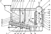
Accompanying drawing is a cut-away view of the present utility model.
Among the figure: 1. reciprocating grate, 2. gas generating chamber, 3. main combustion chamber, 4. secondary furnace, 5. advection heat radiation chamber, 6. boiler body, 7. upper drum, 8. lower drum, 9. go up horizontal collection case, 10. side collection case, 11. convection banks, 12. water screen tubes, 13. upper collecting chamber, 14. outlet pipes, 15. return pipes, 16. the insulation furnace wall, 17. water screen tubes, 18. rear portion partition walls, 19. the smoke shelf plate, 20. gas exits, 21. fuel outlets, 22. the furnace roof wall, 23. partition walls, 24. coal bunkers, 25. the coal seam, 26. flue outlets, 27. times horizontal collection casees, 28. water screen tube, 29. water screen tubes, 30. back furnace wall and heat-insulation layers, 31. oblique brick baffle, 32. perpendicular brick baffles, 33. outlet flues.
The specific embodiment:
Below in conjunction with accompanying drawing concrete structure of the present utility model and embodiment are described again once
Concrete structure
As shown in drawings: the utility model is formed fuel combustion system by reciprocating grate 1, gas generating chamber 2, main combustion chamber 3, secondary furnace 4, advection heat radiation area 5, boiler body 6; Form the working-medium water circulatory system by upper drum 7, lower drum 8, last horizontal collection case 9, side collection case 10, convection bank 11, return pipe 15, outlet pipe 14, water screen tube 12,17,28,29, upper collecting chamber 13, following horizontal collection case 27; In fuel combustion system: gas generating chamber 2 bottoms are reciprocating grate 1, fire grate segment is made by heat-resisting alloy steel, anterior is insulation furnace wall 16, both sides are the furnace wall that lays water screen tube 12, the rear portion partition wall 18 of rear portion for being formed by the refractory concrete ramming is provided with water screen tube 17 in the rear portion partition wall 18, top is provided with gas exit 20, the bottom is provided with fuel outlet 21, and top is the furnace roof wall 22 that lays water screen tube 29; The bottom of main combustion chamber 3, both sides and top are consistent with the structure of gas generating chamber, the front portion of main combustion chamber 3 is the rear portion partition wall 18 of gas generating chamber 2, the partition wall 23 of the rear portion of main combustion chamber 3 for being formed by the refractory concrete ramming is provided with water screen tube 28 in the partition wall 23, the bottom is provided with the lime-ash outlet; The bottom of secondary furnace 4, both sides and top are consistent with the structure of gas generating chamber, oblique brick baffle 31 and the perpendicular brick baffle 32 of the rear portion of secondary furnace 4 for forming by the refractory concrete ramming, and the centre of perpendicular brick baffle 32 has outlet flue 33 and communicates with advection heat radiation chamber 5; There is upper drum 7 top of advection heat radiation chamber 5, and there is lower drum 8 below, and convection bank 11 is installed on every side, and smoke shelf plate 19 is installed in the advection heat radiation chamber 5; In the working-medium water circulatory system: upper drum 7 links with the upper end of upper collecting chamber 13, outlet pipe 14, return pipe 15, convection bank 11, the lower end of convection bank 11 and lower drum 8 link, the upper and lower side of water screen tube 12 links with upper collecting chamber 13 and side collection case 10 respectively, the upper and lower side of water screen tube 17 and water screen tube 28 connects with last horizontal collection case 9 and following horizontal collection case 27 respectively, water screen tube 29 connects with upper collecting chamber 13, go up horizontal collection case 9 and connect with upper collecting chamber 13, following horizontal collection case 27 connects with side collection case 10; Coal bunker 24 is installed in the front upper place of anterior insulation furnace wall 16, and the below of coal bunker 24 communicates with gas generating chamber 2, and flue goes out 26 and is positioned at the top of furnace wall and heat-insulation layer afterwards.
Embodiment
The combustion process of fuel combustion system: coal in the coal bunker 24 is sent on the reciprocating grate 1 in the gas generating chamber 2 by the below, light back bunker coal in gas generating chamber 2 and finish preheating along the vertical direction of fire grate, oxidation and reduction process, the coal gas that produces is discharged to main combustion chamber 3 from the gas exit 20 of gas generating chamber 2, in main combustion chamber 3, mixed the formation high-temperature fuel gas that ignites by the flame on the fire grate, the fuel of complete reaction is not released by fire grate from the fuel outlet 21 of gas generating chamber 2 bottoms, on reciprocating grate 1, burn away and also form high-temperature fuel gas, at last at secondary furnace 4 after-flames, combustion gas is in gas generating chamber 2, finish diabatic process with the working-medium water circulatory system in the main combustion chamber 3 and in the secondary furnace 4, in entering advection heat radiation area 5, smoke 33 finishes heat transfer process again, after flue outlet 26 and chimney enter atmosphere with convection bank 11.
The cyclic process of the working-medium water circulatory system: the heat supply network backwater is squeezed into upper drum 7 by circulating pump through return pipe 15, introduce both sides collection case 10 and following horizontal collection case 27 through the backwater distributing pipe in upper drum 7, again through intussusception the water screen tube 12 of fuel gas calorie, 17,28 are pooled to horizontal collection case 9 and upper collecting chamber 13, enter upper drum 7 at last, intussusception the hot water in the water screen tube 29 of fuel gas calorie also enter upper drum 7 through upper collecting chamber 13, absorbed the convection bank 11 of fuel gas calorie in the advection heat radiation area 5 because the thermic load difference is divided into the rise and fall zone, with last lower drum 7,8 form water circulation in the tube bank together, and last hot water is drawn by the outlet pipe 14 at upper drum 7 tops and sent into heat supply network.
Tiltedly brick baffle 31 plays a part to guide cigarette upwards to move towards to the right, outlet flue 33 on the perpendicular brick baffle 32 makes flue gas be entered in the advection heat radiation area 5 by secondary furnace 4 and discharges through flue outlet 26, smoke shelf plate 19 in the advection heat radiation area 5 plays lengthening plume journey, so that convection bank 11 absorbs more heat.
Claims (1)
1, a kind of reciprocal grate formula coal-coal gas integrated boiler, comprise by reciprocating grate (1), gas generating chamber (2), main combustion chamber (3), secondary furnace (4), advection heat radiation area (5), boiler body (6) and form fuel combustion system and form the working-medium water circulatory system, it is characterized in that by upper drum (7), lower drum (8), last horizontal collection case (9), side collection case (10), convection bank (11), return pipe (15), outlet pipe (14), water screen tube (12,17,28,29), upper collecting chamber (13), following horizontal collection case (27):
A, in fuel combustion system: gas generating chamber (2) bottom is reciprocating grate (1), fire grate segment is made by heat-resisting alloy steel, anterior is insulation furnace wall (16), both sides are for laying the furnace wall of water screen tube (12), the rear portion partition wall (18) of rear portion for being formed by the refractory concrete ramming is provided with water screen tube (17) in the rear portion partition wall (18), top is provided with gas exit (20), the bottom is provided with fuel outlet (21), and top is for laying the furnace roof wall (22) of water screen tube (29); Bottom, both sides and the top of main combustion chamber (3) are consistent with the structure of gas generating chamber, the front portion of main combustion chamber (3) is the rear portion partition wall (18) of gas generating chamber (2), the partition wall (23) of the rear portion of main combustion chamber (3) for forming by the refractory concrete ramming, be provided with water screen tube (28) in the partition wall (23), the bottom is provided with the lime-ash outlet; Bottom, both sides and the top of secondary furnace (4) are consistent with the structure of gas generating chamber, oblique brick baffle (31) and the perpendicular brick baffle (32) of the rear portion of secondary furnace (4) for forming by the refractory concrete ramming, the centre of perpendicular brick baffle (32) has outlet flue (33) and communicates with advection heat radiation chamber (5); There is upper drum (7) top of advection heat radiation chamber (5), and there is lower drum (8) below, and convection bank (11) is installed on every side, and smoke shelf plate (19) is installed in the advection heat radiation chamber (5);
B, in the working-medium water circulatory system: upper drum (7) and upper collecting chamber (13), outlet pipe (14), return pipe (15), the upper end of convection bank (11) links, the lower end of convection bank (11) and lower drum (8) link, the upper and lower side of water screen tube (12) links with upper collecting chamber (13) and side collection case (10) respectively, the upper and lower side of water screen tube (17) and water screen tube (28) connects with last horizontal collection case (9) and following horizontal collection case (27) respectively, water screen tube (29) connects with upper collecting chamber (13), go up horizontal collection case (9) and connect with upper collecting chamber (13), following horizontal collection case (27) connects with side collection case (10); Coal bunker (24) is installed in the front upper place of anterior insulation furnace wall (16), and the below of coal bunker (24) communicates with gas generating chamber (2), and flue outlet (26) is positioned at the top of back furnace wall and heat-insulation layer.
Priority Applications (1)
| Application Number | Priority Date | Filing Date | Title |
|---|---|---|---|
| CNU2005200202527U CN2786439Y (en) | 2005-02-05 | 2005-02-05 | Reciprocating grate type coal-coal gas integrated boiler |
Applications Claiming Priority (1)
| Application Number | Priority Date | Filing Date | Title |
|---|---|---|---|
| CNU2005200202527U CN2786439Y (en) | 2005-02-05 | 2005-02-05 | Reciprocating grate type coal-coal gas integrated boiler |
Publications (1)
| Publication Number | Publication Date |
|---|---|
| CN2786439Y true CN2786439Y (en) | 2006-06-07 |
Family
ID=36775013
Family Applications (1)
| Application Number | Title | Priority Date | Filing Date |
|---|---|---|---|
| CNU2005200202527U Expired - Fee Related CN2786439Y (en) | 2005-02-05 | 2005-02-05 | Reciprocating grate type coal-coal gas integrated boiler |
Country Status (1)
| Country | Link |
|---|---|
| CN (1) | CN2786439Y (en) |
Cited By (5)
| Publication number | Priority date | Publication date | Assignee | Title |
|---|---|---|---|---|
| CN101126504B (en) * | 2007-09-11 | 2010-04-21 | 冯之军 | Coal continuous cleaning burning device and method |
| CN102410521A (en) * | 2011-11-17 | 2012-04-11 | 阳谷祥光铜业有限公司 | Waste heat boiler |
| CN109404882A (en) * | 2018-11-23 | 2019-03-01 | 北京米能科技有限公司 | A kind of miniature boiler and its water round-robin method |
| CN110410773A (en) * | 2019-08-05 | 2019-11-05 | 海伦市利民节能锅炉制造有限公司 | The Combined grated environment-protecting industrial boiler of biomass direct-fired degree and zoning burning phase-splitting |
| CN116972382A (en) * | 2023-09-22 | 2023-10-31 | 河南华泰石化装备股份有限公司 | Ultralow-emission energy-saving environment-friendly biomass boiler and combustion method |
-
2005
- 2005-02-05 CN CNU2005200202527U patent/CN2786439Y/en not_active Expired - Fee Related
Cited By (6)
| Publication number | Priority date | Publication date | Assignee | Title |
|---|---|---|---|---|
| CN101126504B (en) * | 2007-09-11 | 2010-04-21 | 冯之军 | Coal continuous cleaning burning device and method |
| CN102410521A (en) * | 2011-11-17 | 2012-04-11 | 阳谷祥光铜业有限公司 | Waste heat boiler |
| CN109404882A (en) * | 2018-11-23 | 2019-03-01 | 北京米能科技有限公司 | A kind of miniature boiler and its water round-robin method |
| CN110410773A (en) * | 2019-08-05 | 2019-11-05 | 海伦市利民节能锅炉制造有限公司 | The Combined grated environment-protecting industrial boiler of biomass direct-fired degree and zoning burning phase-splitting |
| CN116972382A (en) * | 2023-09-22 | 2023-10-31 | 河南华泰石化装备股份有限公司 | Ultralow-emission energy-saving environment-friendly biomass boiler and combustion method |
| CN116972382B (en) * | 2023-09-22 | 2023-12-19 | 河南华泰石化装备股份有限公司 | Ultralow-emission energy-saving environment-friendly biomass boiler and combustion method |
Similar Documents
| Publication | Publication Date | Title |
|---|---|---|
| CN101949535B (en) | Low-ratio biomass circulating fluidized bed boiler and combustion method thereof | |
| CN2864378Y (en) | Multistage multi-room gas boiler for coal gasification | |
| CN2786439Y (en) | Reciprocating grate type coal-coal gas integrated boiler | |
| CN212339224U (en) | High-temperature oxygen-deficient combustion device for solid fuel | |
| CN1314922C (en) | Horizontal double-layer grate back firing boiler | |
| CN2935003Y (en) | Single drum horizontal type coal hot water boiler with boiler shell coal-saver angle pipe support structure | |
| CN101457981B (en) | Low discharging and high-energy effect novel industrial boiler | |
| CN105004043A (en) | Entrained flow bed hot water boiler | |
| CN1776293B (en) | Heat-storage type honeycomb briquette fired steam boiler | |
| CN2660397Y (en) | Gasified combustion, environmental protection boiler | |
| CN2872196Y (en) | Constant-pressure gasified hot-water boiler of vertical fired coal | |
| CN204987449U (en) | Air current bed boiler | |
| CN2811842Y (en) | Reverse burning type coal gasifying boiler | |
| CN2257895Y (en) | Bidirectionally-burning vertical atmospheric pressure boiler | |
| CN201277699Y (en) | Multi-combustion chamber boiler using anthracite as fuel | |
| CN2379750Y (en) | Boiler using anthracite as fuel | |
| RU2220379C2 (en) | Water heater | |
| CN201382552Y (en) | High-pressure combustion environment-friendly and energy-saving boiler | |
| CN2758592Y (en) | Coal gasifying boiler with double combustion chambers | |
| CN2518028Y (en) | Back-burning multiple water cooling grate thermal tube atmospheric boiler | |
| CN200996621Y (en) | Boiler with front sheding pipe and built-in smoke steering chamber | |
| CN2823840Y (en) | Coal gasification burning boiler | |
| CN202581252U (en) | High-efficiency energy-saving boiler for horizontal two-boiler drum non-refractory material building furnace | |
| CN200986213Y (en) | Post-arch structure of firing space inner traverse S-type flue-gas flow | |
| CN201897212U (en) | Two-stage combustion-supporting reverse burning type combustion furnace |
Legal Events
| Date | Code | Title | Description |
|---|---|---|---|
| C14 | Grant of patent or utility model | ||
| GR01 | Patent grant | ||
| C19 | Lapse of patent right due to non-payment of the annual fee | ||
| CF01 | Termination of patent right due to non-payment of annual fee |