CN201897212U - Two-stage combustion-supporting reverse burning type combustion furnace - Google Patents
Two-stage combustion-supporting reverse burning type combustion furnace Download PDFInfo
- Publication number
- CN201897212U CN201897212U CN2010206387053U CN201020638705U CN201897212U CN 201897212 U CN201897212 U CN 201897212U CN 2010206387053 U CN2010206387053 U CN 2010206387053U CN 201020638705 U CN201020638705 U CN 201020638705U CN 201897212 U CN201897212 U CN 201897212U
- Authority
- CN
- China
- Prior art keywords
- combustion
- furnace
- hearth
- supporting
- burning type
- Prior art date
- Legal status (The legal status is an assumption and is not a legal conclusion. Google has not performed a legal analysis and makes no representation as to the accuracy of the status listed.)
- Expired - Fee Related
Links
Images

Abstract
The utility model discloses a two-stage combustion-supporting reverse burning type combustion furnace, comprising a furnace shell, a hearth and a heat-conducting pipe, wherein the hearth is divided into an upper hearth, a middle hearth and a lower hearth by an upper furnace bar and a lower furnace bar, and is correspondingly provided with an upper furnace door, a middle furnace door and a lower furnace door; the upper furnace hearth and the lower furnace hearth are respectively provided with a combustion-supporting air pipe communicated with the outer side the furnace shell along the tangential line; the combustion-supporting air pipes are connected with a combustion-supporting fan; and the middle hearth is communicated with the heat-conducting pipe. In the two-stage combustion-supporting reverse burning type combustion furnace, the hearth is divided into the three hearths by the two layers of furnace bars; after the upper hearth completes primary combustion, produced volatile components, combustible matters and high-temperature flue gas are reversely blown into the middle hearth and are combusted under the combined action of combustion-supporting gas from the lower hearth, and simultaneously, uncombusted fuel falling from the upper hearth is ignited, so as to lead the fuel to be combusted fully. In the two-stage combustion-supporting reverse burning type combustion furnace, the combustion is fuller, the heat efficiency is higher and pollutants in the flue gas are fewer.
Description
Technical field
The utility model belongs to baking firing equipment technical field, is specifically related to a kind ofly help to make burning more abundant, effectively improves the combustion-supporting counter-burning type combustion furnace of secondary of the thermal efficiency.
Background technology
At present, what the heating furnace in intensive flue-cured tobacco room adopted is single grate design, and through after the primary combustion, a large amount of inflammable substances are discharged with flue gas fire coal in burner hearth, and unburnt fuel is abandoned as slag.The problem that intensive flue-cured tobacco room ubiquity utilization rate of coal is low, the thermal efficiency is not high of prior art.Therefore, not only caused severe energy waste, and serious environment pollution.In the tobacco planting area, because the existence in a large amount of intensive flue-cured tobaccos room, the environmental pollution that fume emission brought has influenced local resident's normal life, even has influenced the self-sow of trees and crops.For this reason, the design people develops a kind of efficiency of combustion height through concentrating on studies, the combustion-supporting counter-burning type combustion furnace of secondary that pollutant emission is low, and evidence, respond well.
The utility model content
The purpose of this utility model is to overcome the deficiencies in the prior art, provides a kind of secondary combustion-supporting counter-burning type combustion furnace, and fuel combustion is more abundant, the thermal efficiency is higher, heating effect is better, is very suitable for intensive flue-cured tobacco room and uses.
The purpose of this utility model is achieved in that and comprises furnace shell, burner hearth and heat pipe; Described burner hearth is separated into upper furnace, middle burner hearth and lower hearth by last grate and following grate, and correspondence is provided with upper furnace door, middle fire door and lower furnace door; Described upper furnace and lower hearth are provided with the combustion-supporting airduct outside tangent line is communicated with furnace shell respectively, and described combustion-supporting airduct connects combustion fan, and described middle burner hearth is communicated with heat pipe.
The utlity model has the combustion furnace of three chamber structures of secondary combustion aid function, fuel is finished once the volatilization composition, inflammable substance and the high-temperature flue gas that are produced after the combustion-supporting burning at upper furnace and is advanced middle burner hearth by blowback, second-time burning under from the combustion-supporting gas acting in conjunction of lower hearth, the upper furnace that ignites simultaneously falls into the uncombusted fuel of burner hearth, and it is fully burnt.In addition, on heat pipe, set up heat exchanger, improved heating efficiency.Therefore, the utility model is heating furnace compared to existing technology, and fuel combustion is more abundant, the thermal efficiency is higher, heating effect is better, and noxious pollutant still less in the discharged flue gas.
Description of drawings
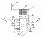
Fig. 1 partly cuts open schematic diagram for the utility model overall structure;
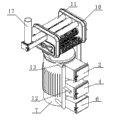
Fig. 2 is that the A of Fig. 1 is to schematic perspective view;
Fig. 3 is that the B of Fig. 1 is to schematic perspective view;
Among the figure: 1-upper furnace, 2-upper furnace door, burner hearth among the 3-, fire door among the 4-, 5-lower hearth, 6-lower furnace door, the 7-furnace shell, 8-heat pipe, 9-heat outlet, the 10-heat exchanger, 11-heat exchanger tube, 12-combustion air house steward, 13-combustion air arm, the last grate of 14-, 15-refractory lining, grate under the 16-, the 17-exhanst gas outlet.
The specific embodiment
Below in conjunction with accompanying drawing the utility model is further described, but never in any form the utility model is limited, any conversion based on the utility model training centre is done all falls into protection domain of the present utility model.
As shown in the figure, the utility model comprises furnace shell 7, burner hearth and heat pipe 8; Described burner hearth is separated into upper furnace 1, middle burner hearth 3 and lower hearth 5 by last grate 14 and following grate 16, and correspondence is provided with upper furnace door 2, middle fire door 4 and lower furnace door 6; Described upper furnace 1 and lower hearth 5 are provided with the combustion-supporting airduct outside tangent line is communicated with furnace shell 7 respectively, and described combustion-supporting airduct connects combustion fan, and described middle burner hearth 3 is communicated with heat pipe 8.
As shown in Figure 2, described combustion-supporting airduct comprises combustion air house steward 12 and combustion air arm 13, and described combustion air house steward 12 is connected with combustion fan, and combustion air arm 13 tangentially is communicated with upper furnace 1 and lower hearth 5 respectively.Integrated to realize feeder, be convenient to operation.
The described heat pipe 8 outer radiating fins that are provided with.
The heat exchanger of being made up of heat exchanger tube 11 10 is set on the described heat pipe 8, and described heat exchanger tube 11 quantity are more than 1.
In above-mentioned the setting, on the heat pipe 8 radiating fin is set and has increased area of dissipation, improved heat dissipation capacity.Can effectively be delivered to the heat supply zone to the heat energy of high-temperature flue gas in the heat pipe 8 by setting up heat exchanger 10.
The described heat exchanger tube 11 outer radiating fins that are provided with.
In the described furnace shell 7 refractory lining 15 is set.
Described upward grate 14 is heat-resisting grate, and following grate 16 is common grate.
Described combustion fan connects automaton.Described automaton connects temperature-detecting device.Automaton is implemented control to the combustion fan air output, can change fired state of the present utility model, and quantity of heat production also changes thereupon.If automaton is connected with temperature-detecting device in the cigarette-filling house, thereby obtain the variations in temperature parameter, adjust the combustion fan air output on this basis, furnace temperature is improved or reduce, better meet the temperature requirements in the cigarette-filling house.
Operation principle of the present utility model:
Burner hearth of the present utility model is separated into three burner hearths by two-layer grate, and upper furnace 1 is the primary combustion zone of fuel, and middle burner hearth 3 is the intermediate zone, and lower hearth 5 is combustion-supporting air inducing and holds gray area.Combustion-supporting airduct of the present utility model is arranged on the furnace shell 7 with tangential direction, and be communicated with upper furnace 1 and lower hearth 5 respectively, its purpose is to make the combustion-supporting gas of importing directly to impact inboard wall of burner hearth, thereby improve the pressure of gas, combustion-supporting gas is fully contacted with fuel, also guaranteed the realization of anti-burning effect.Be after fuel is finished primary combustion in the upper furnace 1, burner hearth 3 during the volatilization composition that is produced, inflammable substance and high-temperature flue gas are advanced from the combustion air blowback of combustion-supporting airduct under the acting in conjunction from the combustion-supporting gas of lower hearth 5, is realized second-time burning; The second-time burning uncombusted fuel that upper furnace 1 falls that also ignites fully burns it.Volatilization composition, inflammable substance and high-temperature flue gas, and the second-time burning of uncombusted broken coal has formed the effect of " biquadratic burning ", burn more abundant, flue-gas temperature is high, can effectively eliminate black smoke, minimizing is to the pollution of environment.
The course of work of the present utility model:
Before the igniting, be paved with fire coal on the grate 14 on the upper furnace 1, on the following grate 16 of middle burner hearth 3, spreading an amount of fire coal, the fire coal in lighting by combustible material in the burner hearth 3; Behind the fired coal combustion of middle burner hearth 3, upper furnace 1 bottom fire coal ignites; Start combustion fan, combustion-supporting gas enters in upper furnace 1 and the lower hearth 5 by combustion-supporting airduct tangent line, and the fire coal of combustion-supporting upper furnace 1 is finished primary combustion.Volatilization composition, inflammable substance and high-temperature flue gas that upper furnace 1 fired coal combustion is produced under the effect of combustion-supporting gas pressure, are advanced in the middle burner hearth 3 by upper furnace 1 blowback; Fire coal in the middle burner hearth 3 is importing under the effect of combustion-supporting gases from lower hearth 5, and coal-fired and volatile combustible matter burns from bottom to top, and volatilization composition, inflammable substance that upper furnace 1 blowback of igniting is got off form second-time burning.In the coal-fired afterburnt that middle burner hearth 3 adds, do not need to add again; In the subsequent combustion process, middle burner hearth 3 is accepted and second-time burning upper furnace 1 unburned or the unburnt broken coal that fall, and blowback the volatilization composition, inflammable substance and the high-temperature flue gas that get off.The burning high-temperature flue gas that forms, the heat outlet 9 of burner hearth 3 enters the heat exchanger 10 on heat pipe 8 and the heat pipe 8 in the warp, is used for heat supply, and the remaining flue gas after the heat exchange is discharged through exhanst gas outlet 17; The formed ashes that burn fall into lower hearth 5 bottoms.
The utility model can be widely used in multiple field as firing equipment, especially needs transformation temperature to satisfy the heat supply process field of need of work.
Characteristics of the present utility model:
1, scientific and reasonable for structure, the more abundant burning of fire coal has improved the thermal efficiency, compares with firing equipment of the same type, calculates by 150 hours, and 20%-30% can be sparing in the use of coal.
2, make burning more abundant by second-time burning, the black smoke in effectively removing smoke reduces the discharging of carbon and inflammable substance, effectively protects environment.
3, owing to thermal efficiency height, realize effectively economizing on coal, thereby reduced workman's coal number of times, improved operating efficiency.
4, the control fire is convenient, accurate, thereby has improved baking quality.
Claims (9)
1. combustion-supporting counter-burning type combustion furnace of secondary, comprise furnace shell (7), burner hearth and heat pipe (8), it is characterized in that: described burner hearth is separated into upper furnace (1), middle burner hearth (3) and lower hearth (5) by last grate (14) and following grate (16), and correspondence is provided with upper furnace door (2), middle fire door (4) and lower furnace door (6); Described upper furnace (1) and lower hearth (5) are provided with the combustion-supporting airduct outside tangent line is communicated with furnace shell (7) respectively, and described combustion-supporting airduct connects combustion fan, and described middle burner hearth (3) is communicated with heat pipe (8).
2. the combustion-supporting counter-burning type combustion furnace of secondary according to claim 1, it is characterized in that: described combustion-supporting airduct comprises combustion air house steward (12) and combustion air arm (13), described combustion air house steward (12) is connected with combustion fan, and combustion air arm (13) tangentially is communicated with upper furnace (1) and lower hearth (5) respectively.
3. the combustion-supporting counter-burning type combustion furnace of secondary according to claim 1 is characterized in that: the outer radiating fin that is provided with of described heat pipe (8).
4. according to claim 1 or the combustion-supporting counter-burning type combustion furnace of 3 described secondarys, it is characterized in that: described heat pipe (8) is gone up the heat exchanger of being made up of heat exchanger tube (11) (10) is set.
5. the combustion-supporting counter-burning type combustion furnace of secondary according to claim 4 is characterized in that: the outer radiating fin that is provided with of described heat exchanger tube (11).
6. the combustion-supporting counter-burning type combustion furnace of secondary according to claim 1 is characterized in that: refractory lining (15) is set in the described furnace shell (7).
7. the combustion-supporting counter-burning type combustion furnace of secondary according to claim 1 is characterized in that: described upward grate (14) is heat-resisting grate, and following grate (16) is common grate.
8. the combustion-supporting counter-burning type combustion furnace of secondary according to claim 1 and 2 is characterized in that: described combustion fan connects automaton.
9. the combustion-supporting counter-burning type combustion furnace of secondary according to claim 8 is characterized in that: described automaton connects temperature-detecting device.
Priority Applications (1)
| Application Number | Priority Date | Filing Date | Title |
|---|---|---|---|
| CN2010206387053U CN201897212U (en) | 2010-12-02 | 2010-12-02 | Two-stage combustion-supporting reverse burning type combustion furnace |
Applications Claiming Priority (1)
| Application Number | Priority Date | Filing Date | Title |
|---|---|---|---|
| CN2010206387053U CN201897212U (en) | 2010-12-02 | 2010-12-02 | Two-stage combustion-supporting reverse burning type combustion furnace |
Publications (1)
| Publication Number | Publication Date |
|---|---|
| CN201897212U true CN201897212U (en) | 2011-07-13 |
Family
ID=44255119
Family Applications (1)
| Application Number | Title | Priority Date | Filing Date |
|---|---|---|---|
| CN2010206387053U Expired - Fee Related CN201897212U (en) | 2010-12-02 | 2010-12-02 | Two-stage combustion-supporting reverse burning type combustion furnace |
Country Status (1)
| Country | Link |
|---|---|
| CN (1) | CN201897212U (en) |
Cited By (1)
| Publication number | Priority date | Publication date | Assignee | Title |
|---|---|---|---|---|
| CN104534455A (en) * | 2014-12-29 | 2015-04-22 | 南京春晓农机有限公司 | Biomass combustion equipment |
-
2010
- 2010-12-02 CN CN2010206387053U patent/CN201897212U/en not_active Expired - Fee Related
Cited By (1)
| Publication number | Priority date | Publication date | Assignee | Title |
|---|---|---|---|---|
| CN104534455A (en) * | 2014-12-29 | 2015-04-22 | 南京春晓农机有限公司 | Biomass combustion equipment |
Similar Documents
| Publication | Publication Date | Title |
|---|---|---|
| CN2879022Y (en) | Biomass vaporization boiler | |
| CN2847051Y (en) | Single boiler tube longitudinal by-path flue pipe sectioned burning constant pressure water heating boiler | |
| CN208735618U (en) | A kind of novel segmentation low nitrogen combustion apparatus | |
| CN203785241U (en) | Thrice combusting hot-air boiler | |
| CN203963897U (en) | A kind of biomass-burning steam boiler | |
| CN201897212U (en) | Two-stage combustion-supporting reverse burning type combustion furnace | |
| CN206626606U (en) | A kind of biomass bundling fuel chain-grate boiler furnace arch structure | |
| CN201212733Y (en) | Vertical double combustion coal burning boiler | |
| CN107664301A (en) | A kind of preparation method of efficient biomass boiler | |
| CN202024368U (en) | Energy-efficient double combustion environment friendly furnace for cooking and heating | |
| CN201662059U (en) | Horizontal type packaged chain grate biomass boiler | |
| CN202382251U (en) | Novel waste incineration boiler | |
| CN201368450Y (en) | Biomass-fired mobile gasification energy-saving boiler | |
| CN206291232U (en) | A kind of negative pressure is ignited separator | |
| CN2350637Y (en) | Backfire type continuous burning domestic refuse incinerator | |
| CN200940928Y (en) | Forward/reverse purifying burning boiler having coal gasifying 3 chambers | |
| CN2926824Y (en) | Environmental-protective economical hot blast furnace of smokeless secondary combustion | |
| CN205332511U (en) | Biomass boiler that positive and negative sintering constructs | |
| CN205137544U (en) | Cooking heating stove with water pipe heat exchanger | |
| CN103353129A (en) | Efficient, clean combustion and low-exhaust gasifying heating stove | |
| CN2458516Y (en) | Incinerator with one burner between two combustion chambers | |
| CN2788021Y (en) | Coal-gasified drum type environment-friendly normal pressure hot-water boiler | |
| CN2859226Y (en) | Vertical water pipe semi-gas environmental protection boiler | |
| CN2797879Y (en) | Smoke purification type coal boiler | |
| CN211694913U (en) | Novel 900t/d high-calorific-value household garbage incinerator |
Legal Events
| Date | Code | Title | Description |
|---|---|---|---|
| C14 | Grant of patent or utility model | ||
| GR01 | Patent grant | ||
| CF01 | Termination of patent right due to non-payment of annual fee |
Granted publication date: 20110713 Termination date: 20141202 |
|
| EXPY | Termination of patent right or utility model |