CN218677180U - Automatic processing and welding equipment for bus bar - Google Patents
Automatic processing and welding equipment for bus bar Download PDFInfo
- Publication number
- CN218677180U CN218677180U CN202223251422.5U CN202223251422U CN218677180U CN 218677180 U CN218677180 U CN 218677180U CN 202223251422 U CN202223251422 U CN 202223251422U CN 218677180 U CN218677180 U CN 218677180U
- Authority
- CN
- China
- Prior art keywords
- bus bar
- feeding
- block
- battery string
- connecting block
- Prior art date
- Legal status (The legal status is an assumption and is not a legal conclusion. Google has not performed a legal analysis and makes no representation as to the accuracy of the status listed.)
- Active
Links
Images


Classifications
-
- Y—GENERAL TAGGING OF NEW TECHNOLOGICAL DEVELOPMENTS; GENERAL TAGGING OF CROSS-SECTIONAL TECHNOLOGIES SPANNING OVER SEVERAL SECTIONS OF THE IPC; TECHNICAL SUBJECTS COVERED BY FORMER USPC CROSS-REFERENCE ART COLLECTIONS [XRACs] AND DIGESTS
- Y02—TECHNOLOGIES OR APPLICATIONS FOR MITIGATION OR ADAPTATION AGAINST CLIMATE CHANGE
- Y02P—CLIMATE CHANGE MITIGATION TECHNOLOGIES IN THE PRODUCTION OR PROCESSING OF GOODS
- Y02P70/00—Climate change mitigation technologies in the production process for final industrial or consumer products
- Y02P70/50—Manufacturing or production processes characterised by the final manufactured product
Abstract
A bus bar automatic processing and welding device comprises a bus bar automatic feeding device, a battery string lifting device and a welding device for welding pins of a battery string and a bus bar; the automatic bus bar feeding device comprises a support, two feeding modules and a processing module for punching/bending the cut bus bar; wherein, the two feeding modules are respectively arranged at the left end and the right end of the bracket; the feeding module comprises a feeding mechanism for releasing the bus bar, a cutting mechanism for cutting the bus bar and a traction mechanism which is arranged on the bracket in a sliding manner and is used for drawing the bus bar; the feeding mechanism, the cutting mechanism and the traction mechanism in each feeding module are sequentially and horizontally arranged along the conveying direction of the bus bar; the setting of two sets of feed modules in the present case has reduced the time of waiting for a set of feed module to cut n section busbar among the prior art for the operation rhythm of whole equipment has improved production efficiency, has practiced thrift manufacturing cost.
Description
Technical Field
The utility model relates to a photovoltaic cell production field, concretely relates to busbar automated processing and welding equipment.
Background
With the development of society and the advancement of technology, photovoltaic power generation plays an increasingly important role in power supply systems. For photovoltaic power generation equipment, battery packs are important parts, each battery pack comprises a left battery string and a right battery string which are symmetrically arranged, each battery string comprises a plurality of battery strings arranged side by side in the width direction of the battery strings, and two wide sides of each battery string are provided with pins for welding. In the production process of the battery assembly, the left and right sides of the two sets of battery strings need to be welded by three (left, middle and right) bus bars. Firstly, arranging a battery string array to be welded on a glass slide, then vertically lifting the arranged battery string upwards through a piece lifting device and suspending the battery string array in the air to leak pins to be welded, and waiting for welding and assembling with a processed bus bar.
Automation equipment among the prior art only includes a set of feed that is used for cutting the whole book busbar and cuts the module, the busbar that cuts is put into the blowing station that has fixed quantity one by one, treat that the busbar on the blowing station is put the back full, move to the machining area again and bend, punch etc. this just leads to cutting the in-process, need wait for n section busbars to be cut completely and just can carry out subsequent processing, the operation rhythm of whole equipment has not only been slowed down to this kind of processing rhythm, make production efficiency be difficult to obtain improving.
Therefore, how to solve the above-mentioned deficiencies of the prior art is a problem to be solved by the present invention.
Disclosure of Invention
The utility model aims at providing a busbar automated processing and welding equipment.
In order to achieve the above purpose, the utility model adopts the technical scheme that: a bus bar automatic processing and welding device comprises a bus bar automatic feeding device, a battery string lifting device and a welding device for welding pins of a battery string and a bus bar;
the automatic bus bar feeding device comprises a support, two feeding modules and a processing module for punching/bending the cut bus bars; wherein, the two feeding modules are respectively arranged at the left end and the right end of the bracket;
the feeding module comprises a feeding mechanism for releasing the bus bar, a cutting mechanism for cutting the bus bar and a traction mechanism which is arranged on the support in a sliding manner and is used for drawing the bus bar; the bus bar is respectively conveyed to the corresponding cutting mechanism from the left end and the right end of the bracket through the two feeding mechanisms; the feeding mechanism, the cutting mechanism and the traction mechanism in each feeding module are sequentially and horizontally arranged along the conveying direction of the bus bar;
the battery string piece lifting device comprises a first adsorption structure and a visual positioning mechanism, wherein the first adsorption structure is used for adsorbing a battery string on a glass slide, and the visual positioning mechanism is used for acquiring the horizontal position of the battery string on the glass slide.
According to a further technical scheme, the automatic bus bar feeding device further comprises a transfer mechanism for driving the processing module to move along the direction perpendicular to the bus bar conveying direction; move and carry mechanism include the base, with processing module fixed connection's connecting block, locate on the base and drive the connecting block along the fourth driver that perpendicular to busbar direction of transfer toward resetting.
According to a further technical scheme, the processing module comprises a material placing station and a bending station for bending the bus bar, and the two stations are sequentially and horizontally arranged along a conveying direction perpendicular to the bus bar; the cut bus bar is positioned in the discharging station; the discharging station is arranged below the traction mechanism correspondingly.
According to a further technical scheme, the processing module further comprises a punching station, and the punching station is located between the discharging station and the bending station.
According to the further technical scheme, the battery string piece lifting device further comprises correction mechanisms corresponding to the number of the battery strings in the battery assembly to be extracted, and each correction mechanism is arranged above the corresponding battery string; each correction mechanism comprises a connecting rod horizontally arranged along the length direction of the battery string and a driving unit for driving the connecting rod to change the position in the horizontal direction; the first adsorption structure is fixedly connected below the connecting rod, and the battery string is horizontally positioned below the connecting rod through the first adsorption structure.
According to a further technical scheme, the driving unit comprises a first connecting block fixedly arranged above the connecting rod and a first driver for driving the first connecting block to move along the Y axis; wherein, the first connecting block is positioned in the middle of the connecting rod; the second connecting block is fixedly arranged above the connecting rod, and the second driver drives the second connecting block to move along the X axis; wherein, the second connecting block sets up with first connecting block interval.
According to the further technical scheme, two second connecting blocks are arranged, two second drivers are arranged, and the two second drivers respectively drive the two second connecting blocks to move along the X axis; the two second connecting blocks are respectively arranged on two sides of the first connecting block to form a structure that the connecting rod is driven by two second drivers to rotate in the horizontal direction or displace along the X axis.
According to a further technical scheme, the battery string piece lifting device further comprises a vertically arranged fixing support, and a connecting plate is horizontally and fixedly arranged below the fixing support; each driver is fixedly connected with the connecting plate; the connecting rod is connected below the connecting plate; strip-shaped holes corresponding to the displacement stroke of each connecting block are formed in the connecting plate above the corresponding connecting block; each driver drives each connecting block to move through a guide rod; each guide rod penetrates through each strip-shaped hole, the upper end of each guide rod is connected with each driver in an assembling mode, and the lower end of each guide rod is fixedly connected with each connecting block.
According to a further technical scheme, the equipment comprises a base plate mechanism for welding the bus bar; the backing plate mechanism comprises backing block structures arranged along the length direction of the bus bar, at least one group of the backing block structures is arranged, and when the backing block structures are arranged in two or more groups, the backing block structures are arranged into long strips along the length direction of the bus bar; the cushion block structure comprises at least one positioning block for bearing and supporting the bus bar and an elastic supporting block assembled below the positioning block.
According to a further technical scheme, the cushion block structure further comprises a supporting plate arranged along the length direction of the bus bar, and grooves corresponding to the elastic supporting blocks one to one are formed in the supporting plate; each elastic supporting block is positioned in each groove, and each positioning block is arranged corresponding to each groove and extends upwards out of the groove.
According to a further technical scheme, the cushion block structure further comprises a supporting plate arranged along the length direction of the bus bar, and grooves corresponding to the elastic supporting blocks one to one are formed in the supporting plate; each elastic supporting block is positioned in each groove, and each positioning block is arranged corresponding to each groove and extends out of the groove upwards.
Compared with the prior art, the utility model the advantages as follows:
the automatic bus bar feeding device comprises two groups of feeding modules, when bus bars are fed, the bus bars are fed from two ends of a support respectively and conveyed to corresponding cutting mechanisms through the two feeding mechanisms respectively, the two cutting mechanisms cut the bus bars at corresponding ends respectively, and the cut bus bars are placed into a discharging station of a processing platform for waiting processing. The setting of two sets of feed modules in the present case has reduced the time of waiting for a set of feed module to cut n section busbar among the prior art for the operation rhythm of whole equipment has improved production efficiency.
Drawings
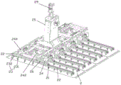
Fig. 1 is a schematic structural diagram of an automation device according to an embodiment of the present invention;
fig. 2 is a schematic structural view of an automatic bus bar feeding device according to an embodiment of the present invention;
FIG. 3 is a schematic structural view of a bracket and a feeding module according to an embodiment of the present invention;
FIG. 4 is a schematic structural view of the processing module and the transplanting mechanism according to the embodiment of the present invention;
fig. 5 is a schematic structural view of a bending station according to an embodiment of the present invention;
FIG. 6 is a schematic structural diagram of a punching mechanism according to an embodiment of the present invention;
fig. 7 is a schematic structural diagram of a carrier table with a limiting structure according to an embodiment of the present invention;
fig. 8 is a first schematic structural diagram (including a battery string) of a battery string lifting device according to an embodiment of the present invention;
fig. 9 is a schematic structural diagram of a battery string lifting device (without a battery string) according to an embodiment of the present invention;
fig. 10 is a schematic structural diagram of a correction mechanism in a battery string sheet lifting device according to an embodiment of the present invention;
FIG. 11 is an exploded view of FIG. 10;
fig. 12 is a schematic view of an assembly structure of the driving unit and the connecting plate in fig. 11 from the bottom view according to the embodiment of the present invention;
FIG. 13 is a schematic structural diagram of a backing plate mechanism according to an embodiment of the present invention;
FIG. 14 is an exploded view of FIG. 13;
FIG. 15 is a schematic view of the structure of FIG. 14 at A;
FIG. 16 is an exploded view of FIG. 15;
fig. 17 is a schematic structural diagram of a battery string welding state in a bus bar and a battery module according to an embodiment of the present invention.
In the above drawings: A. a busbar automatic feeding device; B. a battery string lifting device; C. a welding device;
1. a bus bar; 1a. A first bus bar; 1b. A second busbar; 11. a support;
12. a feeding module; 121. a carrying mechanism; 122. a cutting mechanism; 123. a traction mechanism; 1211. a feeding reel; 1212. a material guide wheel; 13. a processing module; 131. a material placing station; 132. bending a station; 1321. a first carrier stage; 1322. a bending mechanism; 1323. a compression plate; 1323a. A first compression plate; 1323b, a first compression plate; 1324. a pressing cylinder; 1325. a bending member; 1325a. A first bending member; 1325b. A second bending piece; 1326. jacking a cylinder; 133. a punching station; 1331. a second carrier table; 1332. a punching mechanism; 1334. a punch; 1335. a punching cylinder; 1336. a guide groove; 1337. a sliding table; 14. a carrying mechanism; 141. a third adsorption structure; 142. a third suction head; 15. a transplanting mechanism; 151. a base; 152. connecting blocks; 153. a fourth driver; 154. a slide rail; 155. a slider; 16. a limiting structure; 161. a first stopper; 162. a second limiting block; 171. a fourth suction head;
2. a battery string; 21. a correction mechanism; 22. a connecting rod; 23. a first adsorption structure; 231. a suction cup; 232. a vacuum negative pressure gauge; 24. a drive unit; 241. a first connection block; 242. a first driver; 243. a second connecting block; 244. a second driver; 25. fixing a bracket; 26. a connecting plate; 261. a strip-shaped hole; 27. a guide bar; 28. a third connecting block; 29. a third driver; a. a resting site; b. a moving part; c. an inductor; d. an induction sheet;
31. a cushion block structure; 311. positioning blocks; 312. an elastic support block; 313. a support frame; 314. a support plate; 315. a rib plate; 317. a groove; 32. a second adsorption structure; 321. a second suction head; 322. a support block; 323. a gas path hole; 324. an air tube; 325. a one-way cylinder; 326. and a guide block.
Detailed Description
The invention will be further described with reference to the following drawings and examples:
example (b): the present disclosure will be described more fully hereinafter with reference to the accompanying drawings, in which embodiments of the disclosure may be shown and described, and which, when modified and varied by the techniques taught herein, can be made by those skilled in the art without departing from the spirit and scope of the disclosure.
The terminology used herein is for the purpose of describing particular embodiments only and is not intended to be limiting of the disclosure. The singular forms "a", "an", "the" and "the", as used herein, also include the plural forms.
The terms "first," "second," and the like, as used herein, do not denote any order or importance, nor do they denote any order or importance, but rather are used to distinguish one element from another element or operation described in such technical terms.
As used herein, "connected" or "positioned" refers to two or more elements or devices being in direct physical contact with each other or in indirect physical contact with each other, and may also refer to two or more elements or devices being in operation or acting on each other.
As used herein, the terms "comprising," "including," "having," and the like are open-ended terms that mean including, but not limited to.
As used herein, the term (terms), unless otherwise indicated, shall generally have the ordinary meaning as commonly understood by one of ordinary skill in the art, in this application, and in the special art. Certain terms used to describe the disclosure are discussed below or elsewhere in this specification to provide additional guidance to those skilled in the art in describing the disclosure.
The terms "front", "rear", "upper", "lower", "left" and "right" used herein are directional terms, and are used only for describing the positional relationship between the structures, and are not intended to limit the protection schemes and the actual directions of the embodiments.
Referring to fig. 1-17, an automatic bus bar processing and welding device includes an automatic bus bar feeding device a, a battery string lifting device B, and a welding device C for welding the pins of the battery string 2 with the bus bar 1. The welding device C is a conventional technique, and therefore, the present disclosure is not repeated.
Busbar automatic feeding device A: comprises a bracket 11, two feeding modules 12 and a processing module 13; the two feeding modules 12 are respectively disposed at the left and right ends of the support 11, and the left and right directions correspond to the length direction of the support 11.
The feeding module 12 comprises a feeding mechanism 121 for releasing the bus bar 1, a cutting mechanism 122 for cutting the bus bar 1, and a traction mechanism 123 which is slidably arranged on the support 11 and pulls the bus bar 1; the bus bars 1 are respectively fed from the left end and the right end of the bracket 11, and the two specific bus bars 1 are respectively conveyed into the corresponding cutting mechanisms 122 through the two feeding mechanisms 121; the feeding mechanism 121, the cutting mechanism 122, and the pulling mechanism 123 in each feeding module 12 are sequentially and horizontally arranged along the conveying direction of the bus bar 1; the feeding mechanism 121 includes a feeding roller 1211 and a guiding roller 1212, wherein the feeding roller 1211 is driven to convey the bus bar 1 wound in the feeding roller 1211 into the cutting mechanism 122 through the guiding roller 1212; the cutting mechanism 122 includes a cutter structure (not shown) for cutting the bus bar 1.
The processing module 13 comprises a material placing station 131 and a bending station 132 for bending the bus bar 1, wherein the two stations are sequentially and horizontally arranged along a conveying direction vertical to the bus bar 1; the cut bus bar 1 is positioned in the feeding station 131; the emptying station 131 is arranged below the traction mechanism 123.
The emptying station 131 comprises a third carrying table 1311, and the bus bar 1 is positioned in the third carrying table 1311.
The bending station 132 comprises a plurality of first bearing tables 1321 arranged along the length direction of the bus bar 1 and a plurality of bending mechanisms 1322 for bending the bus bar 1 on the first bearing tables 1321 upwards, the first bearing tables 1321 and the bending mechanisms 1322 are both provided in plurality, and each bending mechanism 1322 is arranged between two adjacent first bearing tables 1321) at intervals; the bus bar 1 is positioned in the first carrier 1321, and a free end to be processed (i.e., the end to be bent) extends into the bending mechanism 1322. The bending mechanism 1322 includes two pressing plates 1323, a pressing cylinder 1324 for driving the two pressing plates 1323 to rotate from the side surface of the first bearing platform 1321 to press down and press the bus bar 1 on the platform surface, two bending pieces 1325, and a jacking cylinder 1326 for driving the two bending pieces 1325 to rise and be higher than the platform surface of the first bearing platform 1321. Wherein the first pressing plate 1323a is used for pressing the tail portion of the first bus bar 1a, and the second pressing plate 1323b is used for pressing the head portion of the second bus bar 1 b; the first bending piece 1325a is used for bending the tail of the first bus bar 1a, and the second bending piece 1325b is used for bending the head of the second bus bar 1b, so that the jacking cylinder 1326 can simultaneously drive the two bending pieces 1325 to simultaneously bend the two bus bars 1, and the processing efficiency is improved.
The processing module 13 further comprises a punching station 133, wherein the punching station 133 is located between the discharging station 131 and the bending station 132; the punching station 133 comprises a plurality of second bearing tables 1331 and punching mechanisms 1332 arranged along the length direction of the bus bar 1, the number of the second bearing tables 1331 and the number of the punching mechanisms 1332 are multiple, and each punching mechanism 1332 is arranged between two adjacent second bearing tables 1331; the bus bar 1 is positioned in each of the second loading stages 1331, and the free end to be processed (i.e., the end to be punched) is inserted into the punching mechanism 1332.
The punching mechanism 1332 comprises a supporting table 1333, a punch 1334 suspended on the supporting table 1333, and a punching cylinder 1335 for driving the punch 1334 to move downwards to be lower than the table surface of the supporting table 1333; a guide groove 1336 is formed in the support 1333 just below the punch 1334. The punching mechanism 1332 further includes a sliding table 1337 for facilitating the sliding out of the waste material in the guide groove 1336, and the sliding table 1337 is located at the side of the supporting table 1333, is communicated with the guide groove 1336, and is arranged obliquely downward.
Each of the carrier tables includes a limiting structure 16 for positioning the bus bar 1, the limiting structure 16 includes a first limiting block 161 and a second limiting block 162 protruding from the carrier table, a gap for the bus bar 1 to pass through is formed between the first limiting block 161 and the second limiting block 162, and the gap is consistent with the width of the bus bar 1. First stopper 161 and second stopper 162 and plummer screw-thread fit, as long as set up multiunit screw hole on the plummer like this, the clearance between each group screw hole is different, just so can adjust the size in clearance according to the busbar 1 of different model widths, and then this limit structure 16 can the different model's of adaptation busbar 1. The limiting structure 16 further includes a fourth suction head 171, and the fourth suction head 171 is disposed in each of the bearing tables, located below the bus bar 1, and disposed opposite to the bus bar 1. The vacuum suction head is connected with a negative pressure pump air passage, so as to generate the effect of negative pressure adsorption.
The automatic bus bar feeding device A further comprises a carrying mechanism 14, wherein the carrying mechanism 14 is arranged above the processing module 13 and is driven to reciprocate among the stations to carry the bus bar 1 in the previous station to the next station. The carrying mechanism 14 includes two sets of third adsorption structures 141 for adsorbing the bus bar 1 in the processing module 13, and the two sets of third adsorption structures 141 are respectively arranged corresponding to two adjacent stations in the processing module 13; each set of the third adsorption structures 141 includes a plurality of third suction heads 142 disposed along the length of the bus bar 1.
The automatic bus bar feeding device A also comprises a transfer mechanism 15 for driving the processing module 13 to move along the direction vertical to the bus bar 1; the transfer mechanism 15 includes a base 151, a connecting block 152 fixedly connected to the processing module 13, and a fourth driver 153 disposed on the base 151 and driving the connecting block 152 to move back and forth along a direction perpendicular to the conveying direction of the bus bar 1, where the fourth driver 153 may be a motor or an air cylinder. The transfer mechanism 15 further comprises a slide rail 154 arranged on the base 151, and a slide block 155 reciprocating on the slide rail 154, wherein the slide rail 154 is arranged along a direction perpendicular to the conveying direction of the bus bar 1; the sliding block 155 is fixedly connected with the processing module 13, so that not only is the supporting force of the connecting block 152 on the processing module 13 shared, but also the movement process of the processing module 13 is smoother.
The working principle of the automatic bus bar feeding device is explained as follows: when the device starts to work, the transfer mechanism 15 drives the processing module 13 to displace towards the support 11 along the direction perpendicular to the bus bar 1 conveying direction, so that the discharging station 131 is positioned below the traction mechanism 123, and the bus bar 1 after subsequent cutting is conveniently positioned on the third bearing table 1311 of the discharging station 131.
Firstly, the bus bar 1 is respectively conveyed from the left end and the right end of the bracket to the corresponding cutting mechanism 122 through the feeding mechanisms 121 of the two feeding modules 12 for cutting, namely, the left-side cutting mechanism 122 cuts the bus bar 1 on the left side into a set length, the cut bus bar 1 is pulled and displaced to the right by the left-side pulling mechanism 123 to the upper side of a third bearing table 1311 of the emptying station 131, and is positioned on the third bearing table 1311 by a limiting structure 16 on the third bearing table 1311; meanwhile, the right-side bus bar 1 is cut into a set length by the right-side cutting mechanism 122, the cut bus bar 1 is pulled leftwards by the right-side traction mechanism 123 to move to the position above the third bearing table 1311 of the discharging station 131 and is positioned on the third bearing table 1311 by the limiting structure 16 on the third bearing table 1311, so that the left-side and right-side feeding modules 12 simultaneously cut the bus bars 1 at two ends and are positioned on the third bearing table 1311, the two feeding modules do not interfere with each other, the work of one feeding module 12 in the prior art is divided into two feeding modules 12 to be carried out simultaneously, and the running time of the device is greatly shortened.
When the number of the bus bars 1 on the third bearing table 1311 reaches a set value, the transfer mechanism 15 drives the processing module 13 to move along the direction perpendicular to the bus bar 1 conveying direction and away from the support 11, so that the emptying station 131 is away from the lower side of the traction mechanism 123, and thus the conveying mechanism 14 does not need to wait for returning the two traction mechanisms 123 to the original position and then convey the bus bars 1 on the third bearing table 1311, so that the conveying action of the conveying mechanism 14 and the returning action of the two traction mechanisms 123 are simultaneously performed, the overall operation time of the device is saved, and the operation efficiency of the device is improved.
One of the two sets of third adsorption structures 141 of the carrying mechanism 14 carries the bus bar 1 on the discharging station 131 to the punching station 133 at first, when the punching process is finished, the two sets of third adsorption structures 141 on the carrying mechanism 14 simultaneously carry the bus bar 1 on the discharging station 131 and the bus bar 1 on the punching station 133, the bus bar 1 on the discharging station 131 is respectively placed in the punching station 133, the bus bar 1 on the punching station 133 is placed in the bending station 132, when the punching and bending processes are finished, the two sets of third adsorption structures 141 of the carrying mechanism 14 simultaneously carry the bus bar 1 on the punching station 133 and the bus bar 1 on the bending station 132, the bus bar 1 on the punching station 133 is respectively placed in the bending station 132, the bus bar 1 on the bending station 132 is placed in a set processing completion area, and the subsequent work is waited. The carrying mechanism 14 reciprocates among the stations according to the working procedures and carries the bus bar 1 in the previous station to the next station, and the carrying mechanism 14 can carry the bus bars 1 on the two stations at the same time, so that the running time of the device is shortened, and the feeding efficiency of the device is improved.
The battery string extraction device B comprises a correction mechanism 21 corresponding to the number of the battery strings 2 in the battery string to be extracted and a visual positioning mechanism (not shown in the figure) for acquiring the horizontal position of the battery strings 2 on the glass slide; each of the correction mechanisms 21 is provided above the corresponding battery string 2.
Each of the correction mechanisms 21 includes a link 22 horizontally disposed, a first adsorption structure 23 horizontally positioning the battery string 2 below the link 22, and a drive unit 24 driving the link 22 to move in the horizontal direction; here, the horizontal position change means that the optical pickup device can be moved along the X axis in the horizontal direction, can be moved along the Y axis in the horizontal direction, and can be rotated in the horizontal direction. The length direction of the battery string 2 corresponds to the Y-axis direction, and the width direction of the battery string 2 corresponds to the X-axis direction.
The connecting rod 22 is of a telescopic structure, so that the lifting sheet requirements of the battery strings 2 with different length specifications can be met.
The driving unit 24 comprises a first connecting block 241 fixedly arranged above the connecting rod 22, and a first driver 242 for driving the first connecting block 241 to move along the Y axis; wherein the first connecting block 241 is located at the middle of the connecting rod 22; the connecting rod mechanism further comprises a second connecting block 243 fixedly arranged above the connecting rod 22, and a second driver 244 for driving the second connecting block 243 to move along the X axis; wherein the second connection block 243 is spaced apart from the first connection block 241. When a certain battery string 2 needs to be subjected to Y-axis position correction, the first connecting block 241 is driven by the first driver 242 of the corresponding correction mechanism 21 to perform Y-axis displacement, so that the corresponding connecting rod 22 and the battery string 2 positioned below the connecting rod 22 can be driven to perform Y-axis displacement; when a certain battery string 2 needs to be subjected to X-axis position correction, the second driver 244 of the corresponding correction mechanism 21 drives the second connection block 243 to perform X-axis displacement, so as to drive the corresponding connecting rod 22 and the battery string 2 positioned below the connecting rod 22 to perform X-axis displacement. The first driver 242 and the second driver 244 each include a stationary portion a and a moving portion b, one of the stationary portion a and the moving portion b is provided with a sensing piece d, and the other is provided with a sensor c, so that the moving portion b stops moving when the moving portion b moves to the stationary portion a.
Two second connecting blocks 243 are arranged, two second drivers 244 are arranged, and the two second drivers 244 respectively drive the two second connecting blocks 243 to move along the X axis; the two second connecting blocks 243 are respectively disposed at two sides of the first connecting block 241, so as to realize the rotation of the connecting rod 22 in the horizontal direction or the displacement along the X-axis by being driven by the two second drivers 244. When a certain battery string 2 needs to rotate in the horizontal direction to correct the position, the two second drivers 244 of the corresponding correction mechanisms 21 are only required to drive the two second connection blocks 243 to displace in opposite directions, so as to drive the corresponding connecting rods 22 and the battery string 2 positioned below the connecting rods 22 to rotate.
The driving unit 24 further includes two third connecting blocks 28 connected below the connecting plate 26 to assist the connecting rod 22 to rotate, and the two third connecting blocks 28 are respectively disposed on two sides of the first connecting block 241 and fixedly connected to the connecting rod 22.
The battery string lifting device B further comprises a vertically arranged fixing support 25, and a third driver 29 for driving the fixing support 25 to move in the Z-axis direction is fixedly connected above the fixing support 25. A connecting plate 26 is horizontally and fixedly arranged below the fixed bracket 25; each driver is fixedly connected with the connecting plate 26; the connecting rod 22 is connected below the connecting plate 26; a strip-shaped hole 261 corresponding to the displacement stroke of each connecting block is formed above each connecting block on the connecting plate 26; each driver drives each connecting block to move through a guide rod 27; each guide rod 27 penetrates through each strip-shaped hole 261, the upper end of each guide rod 27 is assembled and connected with each driver, and the lower end of each guide rod 27 is fixedly connected with each connecting block.
The first driver 242, the second driver 244, and the third driver 29 may be one of a motor and a cylinder.
The first adsorption structure 23 is fixedly connected with the connecting rod 22, the first adsorption structure 23 includes a suction cup 231 and a vacuum negative pressure gauge 232 for detecting the vacuum degree in the suction cup 231, and the suction cup 231 is fixedly arranged below the connecting rod 22.
Explanation of the working principle of the battery string lifting device B: firstly, the battery string lifting device B is driven by the third driver 29 to move to the position above the battery string 2 to be lifted, then the battery string lifting device B moves downwards along the Z axis, in the moving process, the visual positioning mechanism acquires the horizontal position of each battery string 2 on the glass slide, then the first adsorption structure 23 positions each battery string 2 on the glass slide below the connecting rod 22 of each correction mechanism 21, and the horizontal position is corrected through the position information of each battery string 2 acquired by the visual positioning mechanism.
When a certain battery string 2 needs to be subjected to Y-axis position correction, the first driver 242 of the corresponding correction mechanism 21 is only required to drive the first connecting block 241 to perform Y-axis displacement, so that the corresponding connecting rod 22 and the battery string 2 positioned below the connecting rod 22 can be driven to perform Y-axis displacement.
When a certain battery string 2 needs to be subjected to X-axis position correction, the second driver 244 of the corresponding correction mechanism 21 drives the second connection block 243 to perform X-axis displacement, so as to drive the corresponding connecting rod 22 and the battery string 2 positioned below the connecting rod 22 to perform X-axis displacement.
When a certain battery string 2 needs to rotate in the horizontal direction to correct the position, the two second drivers 244 of the corresponding correction mechanisms 21 are only required to drive the two second connection blocks 243 to displace in opposite directions, so as to drive the corresponding connecting rods 22 and the battery string 2 positioned below the connecting rods 22 to rotate.
The battery string 2 after the completion of correction is shifted to the setting position through battery string piece lifting device B and is waited for and is assembled with busbar 1 counterpoint, finally carries out welding process, through this action of correction, has promoted the yields among the busbar welding process greatly.
The equipment is still including being used for 1 welded backing plate mechanism of busbar, and this backing plate mechanism includes the cushion structure 31 that sets up along 1 length direction of busbar, and this cushion structure 31 is equipped with a set ofly at least, works as when cushion structure 31 is equipped with two sets of and above, and each group's cushion structure 31 is arranged into long strip along 1 length direction of busbar, and then can adapt the location demand of different length busbars 1.
The spacer structure 31 includes at least one positioning block 311 for bearing and supporting the bus bar 1, and elastic supporting blocks 312 assembled below the positioning block 311 and disposed in one-to-one correspondence with the positioning block 311. When there is one positioning block 311, the length of the positioning block 311 corresponds to the length of the bus bar 1; when the positioning blocks 311 are plural, the positioning blocks 311 are arranged in a long strip shape along the length direction of the bus bar 1 to adapt to the bus bars 1 with different lengths.
The spacer block structure 31 further includes a supporting plate 314 disposed along the length direction of the bus bar 1, and a U-shaped supporting frame 313 disposed below the supporting plate 314, wherein the supporting plate 314 is covered on the supporting frame 313; a rib plate 315 for improving the strength of the lower surface is fixedly connected to the lower surface of the supporting plate 314; the supporting plate 314 is provided with grooves 317 corresponding to the elastic supporting blocks 312 one by one; each elastic supporting block 312 is positioned in each groove 317, and each positioning block 311 is disposed corresponding to each groove 317 and extends upwards out of the groove 317 for bearing and supporting the bus bar 1.
The backing plate mechanism further comprises a second adsorption structure 32 for positioning the bus bar 1 on the upper surface of the positioning block 311, wherein the second adsorption structure 32 comprises a second suction head 321 for adsorbing the bus bar, a guide block 326 sleeved on the periphery of the second suction head 321, and a connecting block 322 arranged below the support plate 314 for supporting the support plate 314; the guide block 326 is positioned below the support plate 314. The second suction head 321 is connected to the connecting block 322, a suction port of the second suction head 321 is arranged corresponding to the upper surface of the supporting plate 314, and when the second suction head 321 sucks the bus bar, the suction port of the second suction head 321 is attached to the bottom of the bus bar on the positioning block 311; an air passage hole 323 is formed in the connecting block 322, and the air passage hole 323 is in air passage communication with the second suction head 321. The second adsorption structure 32 is arranged to more accurately position the bus bar 1 on the positioning block 311, and the position of the bus bar is not changed during the welding process, so that the welding quality is ensured.
At least one group of second adsorption structures 32 is arranged; when two or more sets of the second adsorption structures 32 are provided, the gas path holes 323 on each connection block 322 form gas path communication through the gas pipe 324.
The second adsorption structure 32 further includes a unidirectional cylinder 325 for driving the second suction head 321 to move up and down. When the bus bar 1 to be positioned is displaced downwards to the positioning block 311, the one-way cylinder 325 drives the second suction head 321 to displace upwards and to be higher than the upper surface of the positioning block 311 to meet the bus bar 1 to be positioned, and when the air suction port of the second suction head 321 is attached to the bus bar 1, the one-way cylinder 325 drives the second suction head 321 to displace downwards, so that the bus bar 1 is finally positioned on the upper surface of the positioning block 311, and at this time, the second suction head 321 is still in an adsorption state and is kept until the welding process is finished. Therefore, the bus bar 1 can be more accurately positioned on the positioning block 311, and the position change can not occur in the welding process to ensure the welding quality. The upper end of the one-way cylinder 325 is assembled with the second suction head 321, and the lower end is fixedly connected with the supporting block 322.
Description of the working principle of the shim plate mechanism: in the process that the bus bar 1 to be positioned is displaced downwards to the positioning block 311, the one-way cylinder 325 drives the second suction head 321 to displace upwards and meet the bus bar 1, when the suction port of the second suction head 321 is fitted to the bus bar 1, the second suction head 321 drives the bus bar 1 to displace downwards, so that the bus bar 1 is finally positioned on the upper surface of the positioning block 311, and the continuous suction is performed until the welding process is finished.
In the welding process, the welding head can exert great pressure to the bus bar 1 for the welding effect, because the below of locating piece 311 is equipped with elastic support piece 312, makes the pressure of exerting on the bus bar 1 alleviate to some extent, can not cause the bus bar 1 to damage, can not influence welding operation's effective going on yet, has still improved the yields of bus bar welding process simultaneously.
According to above-mentioned structural component, now just the utility model discloses automation equipment's concrete theory of operation explains as follows:
the bus bars 1 on the left and right sides do not need to be processed by punching, bending, etc., but only need to be cut to a set length, and the intermediate bus bar 2 needs to be processed by cutting, punching, bending, etc. The bus bars 1 on the left and right sides are first cut to a set length by the feeding module 12 and then transferred to a set position to wait for the intermediate bus bar 1. The middle bus bar 1 is cut by the feeding module 12, processed by the processing module 13, conveyed to be converged with the bus bars 1 on the left side and the right side, then conveyed to the backing plate mechanism by the three bus bars 1 on the left side, the middle side and the right side and positioned according to a specified arrangement form, and conveyed to a welding station after the positioning is finished to wait for welding.
The two groups of battery strings 2 to be welded are firstly arrayed on a glass slide, then are conveyed to the position right below a welding station together with the glass slide, then a battery string lifting device B lifts the battery strings 2 on the glass slide upwards and vertically, in the process of lifting upwards, a visual positioning mechanism obtains the horizontal positions of the battery strings 2 and rectifies the battery strings 2 with deviated positions, and the corrected battery strings 2 are shifted to the welding station through the battery string lifting device B to wait for being aligned, welded and assembled with the bus bar 1.
And finally, after the preparation of each bus bar 1 and each battery string 2 is completed, namely the bus bar 1 is positioned right below the pins of the two groups of battery strings 2 and is close to and in contact with the pins, and finally the pins of the battery strings 2 are pressed downwards in a battery welding mode through a welding device C so that the pins of the battery strings 2 are welded and combined with the bus bars 1.
The above embodiments are only for illustrating the technical concept and features of the present invention, and the purpose of the embodiments is to enable people skilled in the art to understand the contents of the present invention and to implement the present invention, which cannot limit the protection scope of the present invention. All equivalent changes and modifications made according to the spirit of the present invention should be covered by the protection scope of the present invention.
Claims (10)
1. The utility model provides a busbar automated processing and welding equipment which characterized in that: the automatic battery string feeding device comprises a bus bar automatic feeding device (A), a battery string lifting device (B) and a welding device (C) for welding pins of a battery string (2) and a bus bar (1);
the automatic bus bar feeding device (A) comprises a support (11), two feeding modules (12) and a processing module (13) for punching/bending the cut bus bar (1); wherein, the two feeding modules (12) are respectively arranged at the left end and the right end of the bracket (11);
the feeding module (12) comprises a feeding mechanism (121) for releasing the bus bar (1), a cutting mechanism (122) for cutting the bus bar (1), and a traction mechanism (123) which is arranged on the support (11) in a sliding manner and is used for drawing the bus bar (1); the bus bar (1) is respectively conveyed to the corresponding cutting mechanism (122) from the left end and the right end of the bracket (11) through the two feeding mechanisms (121); the feeding mechanism (121), the cutting mechanism (122) and the traction mechanism (123) in each feeding module (12) are sequentially and horizontally arranged along the conveying direction of the bus bar (1);
the battery string piece lifting device (B) comprises a first adsorption structure (23) for adsorbing the battery string (2) on the glass slide piece and a visual positioning mechanism for acquiring the horizontal position of the battery string (2) on the glass slide piece.
2. The automated bus bar processing and welding apparatus of claim 1, wherein: the automatic bus bar feeding device (A) further comprises a transfer mechanism (15) for driving the processing module (13) to move along the direction vertical to the conveying direction of the bus bar (1);
move and carry mechanism (15) including base (151), with processing module (13) fixed connection's connecting block (152), locate on base (151) and drive connecting block (152) along the fourth driver (153) that perpendicular to busbar (1) direction of transfer and reset.
3. The automated bus bar processing and welding apparatus of claim 1, wherein: the processing module (13) comprises a material placing station (131) and a bending station (132) for bending the bus bar (1), and the two stations are sequentially and horizontally arranged along the conveying direction vertical to the bus bar (1); the cut bus bar (1) is positioned in the discharging station (131); the emptying station (131) is arranged below the traction mechanism (123).
4. The automated bus bar processing and welding apparatus of claim 3, wherein: the processing module (13) further comprises a punching station (133), and the punching station (133) is positioned between the discharging station (131) and the bending station (132).
5. The automated bus bar processing and welding apparatus of claim 1, wherein: the battery string piece lifting device (B) further comprises correction mechanisms (21) corresponding to the number of the battery strings (2) in the battery assembly to be extracted, and each correction mechanism (21) is arranged above the corresponding battery string (2);
each correction mechanism (21) comprises a connecting rod (22) horizontally arranged along the length direction of the battery string (2) and a driving unit (24) for driving the connecting rod (22) to move horizontally; the first adsorption structure (23) is fixedly connected below the connecting rod (22), and the battery string (2) is horizontally positioned below the connecting rod (22) through the first adsorption structure (23).
6. The automated bus bar processing and welding apparatus of claim 5, wherein: the driving unit (24) comprises a first connecting block (241) fixedly arranged above the connecting rod (22) and a first driver (242) for driving the first connecting block (241) to move along the Y axis; wherein the first connecting block (241) is positioned in the middle of the connecting rod (22);
also comprises a second connecting block (243) fixedly arranged above the connecting rod (22) a second driver (244) for driving the second connecting block (243) to move along the X axis; the second connecting block (243) is arranged at a distance from the first connecting block (241).
7. The automated bus bar processing and welding apparatus of claim 6, wherein: two second connecting blocks (243) are arranged, two second drivers (244) are arranged, and the two second drivers (244) respectively drive the two second connecting blocks (243) to move along the X axis;
the two second connecting blocks (243) are respectively arranged at two sides of the first connecting block (241) to realize the rotation of the connecting rod (22) in the horizontal direction or the displacement along the X axis through the driving of two second drivers (244).
8. The automated bus bar processing and welding apparatus of claim 7, wherein: the battery string sheet lifting device (B) also comprises a vertically arranged fixed support (25), and a connecting plate (26) is horizontally and fixedly arranged below the fixed support (25); each driver is fixedly connected with the connecting plate (26);
the connecting rod (22) is connected below the connecting plate (26); a strip-shaped hole (261) corresponding to the displacement stroke of each connecting block is formed above each connecting block on the connecting plate (26);
each driver drives each connecting block to move through a guide rod (27); each guide rod (27) penetrates through each strip-shaped hole (261), the upper end of each guide rod (27) is connected with each driver in an assembling mode, and the lower end of each guide rod is fixedly connected with each connecting block.
9. The automated bus bar processing and welding apparatus of claim 1, wherein: the equipment also comprises a backing plate mechanism for welding the bus bar (1);
the backing plate mechanism comprises a backing block structure (31) arranged along the length direction of the bus bar (1), at least one group of the backing block structures (31) is arranged, and when the backing block structures (31) are provided with two or more groups, the backing block structures (31) of each group are arranged into long strips along the length direction of the bus bar;
the cushion block structure (31) comprises at least one positioning block (311) for bearing and supporting the bus bar and an elastic supporting block (312) assembled below the positioning block (311).
10. The automated bus bar processing and welding apparatus of claim 9, wherein: the cushion block structure (31) further comprises a supporting plate (314) arranged along the length direction of the bus bar, and grooves (317) corresponding to the elastic supporting blocks (312) one by one are formed in the supporting plate (314); each elastic supporting block (312) is positioned in each groove (317), and each positioning block (311) is arranged corresponding to each groove (317) and extends out of each groove (317) upwards.
Priority Applications (1)
| Application Number | Priority Date | Filing Date | Title |
|---|---|---|---|
| CN202223251422.5U CN218677180U (en) | 2022-12-05 | 2022-12-05 | Automatic processing and welding equipment for bus bar |
Applications Claiming Priority (1)
| Application Number | Priority Date | Filing Date | Title |
|---|---|---|---|
| CN202223251422.5U CN218677180U (en) | 2022-12-05 | 2022-12-05 | Automatic processing and welding equipment for bus bar |
Publications (1)
| Publication Number | Publication Date |
|---|---|
| CN218677180U true CN218677180U (en) | 2023-03-21 |
Family
ID=85548174
Family Applications (1)
| Application Number | Title | Priority Date | Filing Date |
|---|---|---|---|
| CN202223251422.5U Active CN218677180U (en) | 2022-12-05 | 2022-12-05 | Automatic processing and welding equipment for bus bar |
Country Status (1)
| Country | Link |
|---|---|
| CN (1) | CN218677180U (en) |
-
2022
- 2022-12-05 CN CN202223251422.5U patent/CN218677180U/en active Active
Similar Documents
| Publication | Publication Date | Title |
|---|---|---|
| CN219017724U (en) | Stacking device | |
| CN113828967A (en) | Series welding system and series welding process for battery piece | |
| CN103962470A (en) | Automatic material feeding and taking robot | |
| CN210010616U (en) | Series welding machine | |
| CN109759724B (en) | Automatic dicing saw | |
| CN115566108B (en) | Manufacturing method of bus bar | |
| CN113838949A (en) | Solar panel lead-out wire placer | |
| CN218677180U (en) | Automatic processing and welding equipment for bus bar | |
| CN211682482U (en) | Bumper punches a hole and installs radar support's integration tool equipment | |
| CN110323306B (en) | Solar cell string welding bus bar pulling device | |
| CN217806966U (en) | Battery cell stepping carrying device | |
| CN217371527U (en) | Vertical straight-line numerical control tool changing machining center | |
| CN115818313A (en) | Full-automatic material roll feeding system and method | |
| CN210403755U (en) | Solar cell series welding bus bar pulling device | |
| CN218579277U (en) | Automatic bus bar feeding device | |
| CN115740984A (en) | Automatic processing technology of bus bar | |
| CN115121723A (en) | Heat exchanger production line | |
| CN206203382U (en) | Body is drawn in one kind automation fork transmission | |
| CN210305272U (en) | Net-entering machine | |
| CN219338295U (en) | Conveying jacking device for flat plate jig | |
| CN219818260U (en) | Waste material rupture device and processing equipment | |
| CN219324964U (en) | Static iron core guide tube assembly mechanism | |
| CN217126050U (en) | Automatic feeding device | |
| CN213856754U (en) | A storage device and automatic material loading stamping equipment for punching press production | |
| CN215325353U (en) | Flexible centering device |
Legal Events
| Date | Code | Title | Description |
|---|---|---|---|
| GR01 | Patent grant | ||
| GR01 | Patent grant |