CN217436930U - Efficient letter sorting conveying equipment - Google Patents
Efficient letter sorting conveying equipment Download PDFInfo
- Publication number
- CN217436930U CN217436930U CN202220325776.0U CN202220325776U CN217436930U CN 217436930 U CN217436930 U CN 217436930U CN 202220325776 U CN202220325776 U CN 202220325776U CN 217436930 U CN217436930 U CN 217436930U
- Authority
- CN
- China
- Prior art keywords
- conveying
- track
- driving
- lifting
- storage
- Prior art date
- Legal status (The legal status is an assumption and is not a legal conclusion. Google has not performed a legal analysis and makes no representation as to the accuracy of the status listed.)
- Active
Links
Images


Abstract
The utility model discloses an efficient letter sorting conveying equipment uses in letter sorting transport field, has solved current conveying equipment fortune material frame and has needed artifical transport, leads to the technical problem that conveying efficiency is not high, and its technical scheme main points are: comprises a frame and a conveying track arranged on the frame; the storage track is arranged below the conveying track along the vertical direction, and the unloading platform is used for unloading the goods; the first lifting and conveying mechanism is used for conveying goods among the conveying track, the storage track and the unloading platform; the second lifting and conveying mechanism is used for conveying goods between the conveying track and the storage track; the storage track comprises a storage guide rail, an in-place sensor and a blocking assembly, wherein the storage guide rail is fixed on the rack in parallel with the length direction of the conveying track; has the technical effects that: can be through depositing the effect of keeping in of track to the fortune workbin for the fortune workbin can get into the delivery track fast, improves transport efficiency.
Description
Technical Field
The utility model relates to a field, in particular to efficient letter sorting conveying equipment are carried in the letter sorting.
Background
Sorting is to carry products in different categories, is a method which needs to be frequently used in logistics and assembly line production, and generally puts different products into different material frames for classified transportation when transporting the sorted products.
At present, the chinese patent application with publication number CN112173581A discloses a novel rail type belt conveyor, which comprises a driving roller, a driven roller, a conveyor belt, a direct drive motor, a carrier roller, a belt supporting trolley, an inner rail, a circular tube rail, an arc rail, and a main truss. The belt supporting trolley comprises a roller, a pulley, a bracket, a roll-over stand and a pin hole. The upper end of the belt supporting trolley is an inverted trapezoid supporting conveying belt, the lower end roller is connected in series with the inner rail through a traction rope and rolls on the inner rail, and the upper end pulley slides on the circular tube rail. The belt supporting trolley is separated from the conveying belt at the supporting roller, the belt supporting trolley changes the direction from the bearing layer to the idle layer through the arc-shaped track, and the clamping conveying belt is jointed with the belt supporting trolley again after the overturning frame overturns.
The existing steel classifying and conveying device can be used for classifying and conveying different products, but in the using process, a material conveying box needs to be conveyed to a conveyor manually, and the problems of manpower consumption and low efficiency exist.
SUMMERY OF THE UTILITY MODEL
The utility model aims at providing an efficient letter sorting conveying equipment, its advantage is that can supplement through the incessant circulation of fortune workbin, and the efficient is accomplished the conveying work to the product, and can reduce artificial use.
The above technical object of the present invention can be achieved by the following technical solutions: an efficient sorting and conveying device comprises a rack and a conveying track arranged on the rack;
the storage track is arranged below the conveying track, and the unloading platform is used for unloading the goods;
the first lifting and conveying mechanism is used for conveying goods among the conveying track, the storage track and the unloading platform;
the second lifting and conveying mechanism is used for conveying goods between the conveying track and the storage track;
the storage rail comprises a storage guide rail arranged on the rack, an in-place sensor and a blocking assembly used for limiting the position of goods on the storage rail, and the storage guide rail is parallel to the conveying rail;
the in-place sensors and the blocking assemblies are uniformly arranged on the storage track.
Through the technical scheme, the storage track is used for temporarily storing the material conveying box for conveying goods below the conveying track; the unloading platform is used for unloading the goods; the first lifting transmission mechanism is used for conveying goods among the conveying track, the storage track and the unloading platform; the second lifting and conveying mechanism is used for conveying the material conveying box between the conveying rail and the storage rail; the in-place sensor can detect the position to which the material conveying box moves, so that a basis is provided for the next operation of the equipment; the blocking assembly can block the material transporting box from moving on the storage guide rail when the material transporting box needs to stop moving, so that a plurality of goods can be temporarily stored in the storage rail, the equipment can directly work when being started, and the material transporting box is smoothly operated in the operation process, and the conveying efficiency is improved.
The utility model is further provided with that the blocking component comprises a fixed plate arranged on the frame and a blocking block rotationally connected with the fixed plate; and the fixed plate is provided with a swing driving assembly for driving the stop block to rotate.
Through the technical scheme, the fixing plate is used for fixing the blocking assembly on the rack; the blocking block can be lifted relative to the fixing plate, so that the material conveying box is limited at a specific position on the storage track; the swing driving assembly is used for driving the blocking block to lift or fall relative to the fixed plate so as to control the starting and stopping of the material conveying frame on the storage track; thereby prevent that the fortune workbin from depositing the jam on the track, influencing conveying efficiency.
The utility model discloses further set up to: the discharging platform comprises a discharging roller, a driving mechanism and a discharging support frame;
the driving mechanism comprises a plurality of double-row chain wheels, a single-row chain wheel and a driving motor;
the double-row chain wheel is fixed at the end part of the discharging roller;
the single-row chain wheel is fixedly connected with the driving motor;
the double-row chain wheel is connected with the single-row chain wheel through a chain;
the plurality of double-row chain wheels are connected through chains.
Through the technical scheme, the unloading roller drives the material conveying box to enter and exit the unloading platform through rotation; the double-row chain wheels are connected, and one double-row chain wheel can be driven to rotate by the driving motor so as to drive all the double-row chain wheels to rotate and further drive all the discharging rollers to rotate; for moving the magazines into and out of the discharge table, instead of manually moving the magazines between the conveyor track and the storage track.
The utility model discloses further set up to: the first lifting transmission mechanism and the second lifting transmission mechanism comprise a driving assembly, a transmission assembly and a vertical sliding rod, wherein the driving assembly is used for driving the lifting frame to move up and down;
the conveying assembly comprises a conveying roller and a supporting frame;
the driving mode of the conveying roller is the same as that of the discharging roller;
the supporting frame is connected to the vertical sliding rod in a sliding manner;
the transmission roller is rotatably connected to the support frame.
Through the technical scheme, the vertical sliding rod is used for the supporting frame to slide along the arrangement direction of the supporting frame, so that the moving direction of the supporting frame relative to the ground can be limited; the supporting frame is connected with the conveying roller and the vertical sliding rod to drive the conveying roller to move along the direction of the vertical sliding rod; the conveying roller rotates to drive the goods to enter and exit the first lifting conveying mechanism and the second lifting conveying mechanism; the driving assembly provides power for the supporting frame to move downwards along the direction of the vertical sliding rod, so that manual work is replaced for conveying the conveying box between the conveying rail and the storage rail.
The utility model discloses further set up to: the driving assembly comprises a driving motor and a driving lifting rod;
two ends of the driving lifting rod are respectively fixedly connected with the bottom plate and the supporting frame;
the driving lifting rod can be stretched up and down;
the driving motor is electrically connected with the driving lifting rod;
the driving motor has an electromagnetic braking function;
through the technical scheme, the lifting rod is driven to extend up and down to drive the supporting frame to move up and down and further drive the conveying roller to move up and down; the driving motor provides power for the extension of drive lifter to open and stop of control drive lifter at any time through the electromagnetic braking function, make the conveying cylinder can block at the discharge table position and stop, make the fortune workbin can reach the discharge table through first lifting unit.
The utility model discloses further set up to: the driving component of the second lifting transmission mechanism can be a driving cylinder;
the end part of the cylinder body of the driving cylinder is fixedly connected with the ground, and the end part of the piston rod of the driving cylinder is fixedly connected with the supporting frame.
Through above-mentioned technical scheme, the actuating cylinder that drives of second lift transport mechanism drives the carriage through cylinder piston rod's flexible and reciprocates, makes transfer drum can be at the delivery track and deposit the interorbital removal to replace the manual work to carry the transport case from top to bottom.
The utility model discloses further set up to: the storage track is also provided with a conveying wheel and a driving motor for driving the conveying wheel to rotate;
the conveying wheels are densely paved on the storage guide rail
Through above-mentioned technical scheme, driving motor drives the transfer gear and rotates, and the transfer gear drives the goods and removes on depositing the track.
The utility model discloses further set up to: the in-place sensors are provided with rotatable arm rods, and the in-place sensors are uniformly arranged at one end, close to the second lifting and conveying mechanism, of the storage track;
through above-mentioned technical scheme, the inductor that targets in place can give the controller with signal transmission after the fortune workbin reachs preset position, and controller transmission signal blocks the subassembly and rises, fixes the fortune workbin in at preset position.
To sum up, the utility model discloses following beneficial effect has:
can be through depositing the effect of keeping in of track to the workbin for the workbin can get into the very first time when needs get into the delivery track, has improved transport efficiency.
Drawings
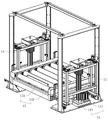
Fig. 1 is an overall configuration diagram of the present embodiment;
FIG. 2 is a schematic structural diagram of a first elevating and transferring mechanism of the present embodiment;
FIG. 3 is a schematic structural diagram of a second elevating and transferring mechanism of the present embodiment;
FIG. 4 is a schematic structural view of a discharge table of the present embodiment;
FIG. 5 is an enlarged schematic view of portion A of FIG. 1;
FIG. 6 is an enlarged schematic view of portion B of FIG. 4;
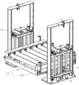
fig. 7 is a partial schematic view of the conveying track and the storage track of the present embodiment;
FIG. 8 is a schematic structural view of a storage track of the present embodiment;
FIG. 9 is an enlarged schematic view of portion C of FIG. 8;
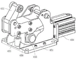
fig. 10 is a schematic structural view of the barrier assembly of the present embodiment.
Reference numerals: 1. a first lifting and conveying mechanism; 2. a second lifting and conveying mechanism; 3. a conveying track; 4. storing the track; 5. a discharge platform; 6. a controller; 7. a material conveying box; 8. a base plate; 11. a drive assembly; 12. a lifting frame; 13. a transfer assembly; 14. a vertical slide bar; 15. lifting rollers; 21. a driving cylinder; 31. a conveying roller set; 32. a signal detector; 41. storing the guide rail; 42. a transfer wheel; 43. a drive motor; 44. an in-place sensor; 45. a blocking component; 46. a frame; 51. a discharging roller; 52. a discharging support frame; 54. a discharging motor; 55. a gear cover; 111. a lifting motor; 112. driving the lifting rod; 131. a transfer drum; 132. a support frame; 311. a conveying roller; 312. double-row chain wheels; 314. a single row of sprockets; 441. an arm lever; 451. a fixing plate; 452. a blocking block; 453. a connecting rod; 454. a blocking cylinder; 455. a rotating wheel; 456. and (6) a bump.
Detailed Description
The present invention will be described in further detail with reference to the accompanying drawings.
Example (b):
referring to fig. 1, an efficient sorting and conveying apparatus includes a material conveying box 7, a first lifting and conveying mechanism 1, a second lifting and conveying mechanism 2, a conveying rail 3, a storage rail 4, a discharging table 5 and a controller 6; the first lifting and conveying mechanism 1, the second lifting and conveying mechanism 2, the storage track 4 and the discharging platform 5 are fixed on the ground; the conveying track 3 is welded and fixed above the storage track 4; the first lifting transmission mechanism 1 and the second lifting transmission mechanism 2 are respectively arranged at two ends of the conveying track 3 and the storage track 4; the discharging platform 5 is arranged on one side of the first lifting and conveying mechanism 1, which is far away from the conveying track 3 and the storage track 4; the controller 6 is fixed on the ground.
Referring to fig. 4, the discharging table 5 includes a plurality of discharging rollers 51, a discharging support frame 52, and a signal detector 32; the discharging support frame 52 is fixed on the bottom plate 8, and the discharging roller 51 is rotationally connected to the discharging support frame 52; the signal detector 32 is fixed on the discharging support frame 52, is in electric signal connection with the controller 6, and is used for transmitting information to the controller 6 through electric signals when the material conveying frame enters or exits the discharging platform 5, and the controller 6 sends a signal of further command to the equipment.
Referring to fig. 4 and 6, the plurality of discharging rollers 51 arranged on the discharging table 5 are driven by a discharging motor 54, the discharging motor 54 is fixed on a discharging support frame 52, the discharging motor 54 is connected with a single-row chain wheel 314 through a gear set, and the discharging motor 54 drives the single-row chain wheel 314 to rotate; the discharging roller 51 is connected with double-row chain wheels 312 in an interference manner, one gear tooth of one double-row chain wheel 312 is connected with a single-row chain wheel 314 through a chain, the single-row chain wheel 314 rotates to drive the chain to rotate, and the chain further drives the double-row chain wheel 312 to rotate; the other teeth of the duplex chain wheels 312 are connected by a chain, so that the rotation of one duplex chain wheel 312 drives all the duplex chain wheels 312 to rotate, and further drives all the discharging rollers 51 to rotate, so as to drive the material conveying box 7 to move on the discharging platform 5.
Referring to fig. 2, the first elevation transport mechanism 1 includes a driving assembly 11, a transport assembly 13, an elevation frame 12, and a vertical slide 14; the vertical sliding rod 14 is vertically fixed on the bottom plate 8; the lifting frame 12 is a rectangular frame body, the eight vertex angles are rotatably connected with lifting rollers 15, the axial included angle of the rotating shafts of the two adjacent lifting rollers 15 is a right angle, the axial is parallel to the bottom plate 8, and the lifting frame 12 is connected with the vertical sliding rod 14 in a sliding manner through the lifting rollers 15; the conveying assembly 13 comprises a conveying roller 131 and a supporting frame 132, the supporting frame 132 is a rectangular frame, and the supporting frame 132 is welded and fixed on the lifting frame 12 and is parallel to the bottom plate 8; the transmission rollers are rotatably connected to the supporting frame 132, a plurality of transmission rollers 131 are uniformly laid along the length direction of the supporting frame 132, and the transmission rollers are driven in the same manner as the discharging rollers.
The driving assembly 11 comprises a driving lifting rod 112 and a lifting motor 111, wherein the driving lifting rod 112 comprises an outer rod and an inner rod connected inside the outer rod in a sliding manner; the outer rod and the inner rod are connected in a sliding mode, one end of the inner rod is fixedly connected with the bottom plate 8, the end, far away from the outer rod, of the inner rod is in interference fit with the lifting frame 12, the lifting motor 111 drives the inner rod to stretch up and down to drive the lifting frame 12 to move up and down, and then the conveying roller 131 is driven to move up and down.
The lifting motor 111 has an electromagnetic braking function, and can be started and stopped at any time in the up-and-down moving process in order to control the conveying roller 131, and the height of the discharging platform 5 can be matched, so that the material conveying frame can be conveyed back and forth between the discharging platform 5 and the first lifting conveying mechanism 1.
Referring to fig. 1 and 5, the conveying rail 3 is fixed on the bottom plate 8 through a frame 46, the conveying rail 3 is provided with a plurality of groups of conveying roller groups 31 and a plurality of signal detectors 32, and the plurality of signal detectors 32 are uniformly fixed on the conveying rail 3 and used for detecting the moving position of the transport box 7 on the conveying rail 3.
Each conveying roller set 31 comprises a plurality of conveying rollers 311, a single row of chain wheels 314 and a driving motor 43; the single-row chain wheel 314 is in interference fit with the driving motor 43, and the driving motor 43 drives the single-row chain wheel 314 to rotate; the end of each conveying roller 311 is connected with a double-row chain wheel 312 in an interference manner, one gear tooth of one double-row chain wheel 312 is connected with a single-row chain wheel 314 through a chain, the single-row chain wheel 314 rotates to drive the chain to rotate, and the chain further drives the double-row chain wheel 312 to rotate; the other wheel teeth of the duplex sprocket 312 are connected by a chain, so that the rotation of one duplex sprocket 312 drives all the duplex sprockets 312 to rotate, thereby driving all the conveying rollers 311 of each conveying roller group 31 to rotate. Each group of conveying roller sets 31 are driven by an independent driving motor 43, so that each group of conveying roller sets 31 can be started and stopped as required, and the material conveying box 7 can be systematically conveyed on the conveying track 3.
Referring to fig. 8 and 9, the storage track 4 includes a frame 46, a transfer wheel 42, a storage rail 41, a driving motor 43, a position sensor 44 and a blocking assembly 45, the storage rail 41 is welded and fixed on the frame 46 in parallel with the bottom plate 8, and the length direction of the storage rail 41 is the same as that of the upper storage rail 41; the conveying wheels 42 are densely paved in the storage guide rail 41 and are used for driving the transportation box 7 to move on the storage guide rail 41; the driving motor 43 is fixed at the end of the storage rail 41, and the driving motor 43 is connected to a gear train which drives each of the transfer wheels 42 to rotate.
The in-place sensor 44 is fixed on the frame 46 and is electrically connected with the controller 6, the in-place sensor 44 is provided with a rotatable arm 441, and when the arm 441 is deflected to a certain angle, an electric signal can be sent to the controller 6; during the transportation of the material box 7, the material box 7 passing the position sensor 44 deflects the arm 441 of the position sensor 44, so that the controller 6 knows the position where the material box 7 passes.
Referring to fig. 8 and 10, the blocking assembly 45 includes a fixing plate 451, a blocking block 452, a connecting rod 453, a rotating wheel 455, and a blocking cylinder 454; the fixed plate 451 is in threaded connection with the frame 46, and two connecting plates are vertically arranged on the fixed plate 451; one end of the connecting rod 453 is rotatably connected between the two connecting plates through a rotating shaft, and the blocking block 452 is in bolted connection with one end of the connecting rod 453 far away from the connecting plates; the end of the stopper 452 remote from the connecting rod 453 is rotatably connected with a rotating wheel, and the stopper 452 and the rotating wheel are used for clamping the transportation box 7 and stopping the transportation box 7 from continuously moving on the storage track 4.
The blocking cylinder 454 is welded and fixed on the fixing plate 451, the end of the piston rod of the blocking cylinder 454 is rotatably connected with a rotating wheel 455, the lower end of the connecting rod 453 is integrally formed with a projection 456 which abuts against the rotating wheel 455, one surface of the projection 456 which abuts against the rotating wheel 455 comprises a flat surface and an inclined surface, the blocking cylinder 454 drives the rotating wheel 455 to move on the flat surface and the inclined surface, when the rotating wheel 455 moves on the inclined surface, the height of the blocking block 452 is increased or decreased, and when the rotating wheel 455 moves on the flat surface, the blocking block 452 is at the best position to block the further movement of the transportation box 7.
Referring to fig. 3, the second elevation transport mechanism 2 is different from the first elevation transport mechanism 1 in that a driving cylinder 21 is used in the driving unit 11 of the second elevation transport mechanism 2, a piston rod of the driving cylinder 21 is in interference fit with the elevation frame 12, and the cylinder drives the piston rod to move up and down, thereby driving the transport roller 131 to move between the transport rail 3 and the storage rail 4.
The using process is briefly described as follows: before the apparatus is started, the storage track 4 is filled with the transport containers 7, the stop block 452 is raised to the maximum height, and each transport container 7 is fixed at a predetermined position; after the equipment is started, the controller 6 sends a signal to the blocking assembly 45, the blocking blocks 452 descend in sequence, so that the material conveying boxes 7 move sequentially according to the distance sequence from the second lifting conveying mechanism 2, when the first material conveying box 7 reaches the second lifting conveying mechanism 2, the second material conveying box 7 touches the in-place sensor 44 at the position of the first material conveying box 7, the in-place sensor 44 sends a signal to the controller 6, and the controller 6 controls the blocking blocks 452 to ascend to fix the material conveying boxes 7 on the storage track 4; the driving assembly 11 of the second lifting and conveying mechanism 2 drives the conveying roller 131 to move upwards, so as to drive the material conveying box 7 to move upwards, and the material conveying box 7 is conveyed to the conveying rail 3.
After the material conveying box 7 reaches the same height as the conveying track 3, the conveying rollers 131 rotate to convey the material conveying box 7 to the first group of conveying roller sets 31 of the conveying track 3, then the material conveying box is conveyed to the subsequent group of conveying rollers 31 continuously through the first group of conveying roller sets 31, and after the material conveying box reaches a preset position, the conveying roller sets 31 bearing the material conveying box 7 stop rotating, so that the material conveying box 7 stops on the conveying track 3; when the first material conveying box 7 is conveyed, the subsequent material conveying box 7 is conveyed, after the same material conveying box reaches a preset position, sorted articles are placed on different material conveying boxes 7 respectively, after the material conveying box 7 is placed, the first lifting conveying mechanism 1 is moved to the first lifting conveying mechanism 7, the first lifting conveying mechanism 1 drives the material conveying box 7 to enter the discharging table 5, the material is discharged through the discharging table 5 and then reaches the storage rail 4 through the first lifting conveying mechanism 1 to be stored, and then the material conveying box is moved to the second lifting conveying mechanism 2 in sequence, so that the conveying work after the sorting is finished in a circulating and efficient mode.
The present embodiment is only for explaining the present invention, and it is not limited to the present invention, and those skilled in the art can make modifications to the present embodiment without inventive contribution as required after reading the present specification, but all of them are protected by patent laws within the scope of the claims of the present invention.
Claims (8)
1. An efficient sorting and conveying device comprises a rack (46) and a conveying track (3) arranged on the rack (46);
the device is characterized by also comprising a storage track (4) arranged below the conveying track (3) and a discharge platform (5) used for discharging the goods;
the first lifting and conveying mechanism (1) is used for conveying goods among the conveying track (3), the storage track (4) and the unloading platform (5);
the second lifting and conveying mechanism (2) is used for conveying goods between the conveying track (3) and the storage track (4);
the storage rail (4) comprises a storage guide rail (41) arranged on the rack (46), an in-position sensor (44) and a blocking assembly (45) used for limiting the position of goods on the storage rail (4), and the storage guide rail (41) is parallel to the conveying rail (3);
the in-place sensors (44) and the blocking assemblies (45) are uniformly arranged on the storage track (4).
2. An efficient sorting and conveying apparatus according to claim 1, characterized in that the blocking assembly (45) comprises a fixed plate (451) provided on a frame (46) and a blocking block (452) rotatably connected to the fixed plate (451); the fixed plate (451) is provided with a swing driving assembly for driving the stop block (452) to rotate.
3. An efficient sorting conveyor device according to claim 1, characterized in that said discharge table (5) comprises discharge rollers (51), a drive mechanism and a discharge support frame (52);
the driving mechanism comprises a plurality of double-row chain wheels (312), a single-row chain wheel (314) and a driving motor (43);
the double-row chain wheel (312) is fixed at the end part of the discharging roller (51);
the single-row chain wheel (314) is fixedly connected with the driving motor (43);
the double-row chain wheel (312) is connected with the single-row chain wheel (314) through a chain;
the plurality of double-row chain wheels (312) are connected through chains.
4. A high-efficiency sorting and conveying device according to claim 3, wherein the first lifting and conveying mechanism (1) and the second lifting and conveying mechanism (2) comprise a driving assembly (11) for driving the lifting frame (12) to move up and down, a conveying assembly (13) and a vertical sliding rod (14);
the conveying assembly (13) comprises a conveying roller (131) and a supporting frame (132);
the driving mode of the conveying roller (131) is the same as that of the discharging roller (51);
the supporting frame (132) is connected to the vertical sliding rod (14) in a sliding manner;
the conveying roller (131) is rotatably connected to the supporting frame (132).
5. The efficient sortation conveyor of claim 4, wherein said drive assembly (11) comprises a drive motor (43) and a drive lift rod (112);
two ends of the driving lifting rod (112) are respectively and fixedly connected with the bottom plate (8) and the supporting frame (132);
the driving lifting rod (112) can be stretched up and down;
the driving motor (43) is electrically connected with the driving lifting rod (112);
the drive motor (43) has an electromagnetic braking function.
6. An efficient sorting conveyor device according to claim 5, characterized in that the driving assembly (11) of the second lifting and transferring mechanism (2) can be a driving cylinder (21);
the end part of the cylinder body of the driving cylinder (21) is fixedly connected with the ground, and the end part of the piston rod of the driving cylinder (21) is fixedly connected with the supporting frame (132).
7. An efficient sorting and conveying apparatus according to claim 1, wherein the storage track (4) is further provided with a conveying wheel (42) and a driving motor (43) for driving the conveying wheel (42) to rotate;
the conveying wheels (42) are densely paved on the storage guide rail (41).
8. An efficient sorting conveyor apparatus according to claim 1, wherein said position sensor (44) has a rotatable arm (441), and a plurality of said position sensors (44) are uniformly arranged on the end of the storage track (4) near the second lifting conveyor (2).
Priority Applications (1)
| Application Number | Priority Date | Filing Date | Title |
|---|---|---|---|
| CN202220325776.0U CN217436930U (en) | 2022-02-18 | 2022-02-18 | Efficient letter sorting conveying equipment |
Applications Claiming Priority (1)
| Application Number | Priority Date | Filing Date | Title |
|---|---|---|---|
| CN202220325776.0U CN217436930U (en) | 2022-02-18 | 2022-02-18 | Efficient letter sorting conveying equipment |
Publications (1)
| Publication Number | Publication Date |
|---|---|
| CN217436930U true CN217436930U (en) | 2022-09-16 |
Family
ID=83214091
Family Applications (1)
| Application Number | Title | Priority Date | Filing Date |
|---|---|---|---|
| CN202220325776.0U Active CN217436930U (en) | 2022-02-18 | 2022-02-18 | Efficient letter sorting conveying equipment |
Country Status (1)
| Country | Link |
|---|---|
| CN (1) | CN217436930U (en) |
-
2022
- 2022-02-18 CN CN202220325776.0U patent/CN217436930U/en active Active
Similar Documents
| Publication | Publication Date | Title |
|---|---|---|
| CN108499884B (en) | Sweep post-arranged commodity circulation letter sorting system of sign indicating number | |
| CN106892276B (en) | Section steel stacker crane and automatic grouping and stacking method thereof | |
| CN108480221B (en) | Logistics sorting system comprising equidistant separation, slow flow separation and fast flow combination | |
| CN108499883B (en) | Package sorting method based on independent address code scanning sorter | |
| CN108453062B (en) | Package sorting method based on speed matching principle | |
| CN207479012U (en) | A kind of double sheets sorting device | |
| CN113200373A (en) | Automatic loading device | |
| CN109775286A (en) | A kind of loading system and loading method | |
| US3325021A (en) | Stack handling apparatus | |
| CN108453048B (en) | Package sorting method based on vertical stacking type sorter | |
| CN213386544U (en) | Thing networking intelligent gas table production material loading transfer chain | |
| CN217436930U (en) | Efficient letter sorting conveying equipment | |
| CN116216341B (en) | Automatic doffing stacking system for production line of twisting machine | |
| CN112693819A (en) | Electric automobile battery package is changed and is used digital lift | |
| CN111570290A (en) | Interval overturning type sorting system for intelligent logistics packages | |
| CN109178746B (en) | Three-dimensional warehousing system | |
| CN217534671U (en) | Automatic egg tart skin stacking device | |
| CN215159357U (en) | Automatic loading device | |
| CN115783789A (en) | Automatic container stacking robot matched with logistics conveying and working method thereof | |
| CN214455123U (en) | Gravure roller storage transfer platform of veneer material printing machine | |
| CN212821174U (en) | Interval overturning type sorting system for intelligent logistics packages | |
| CN214059263U (en) | Bagged cargo unstacking and loading system | |
| CN210312329U (en) | Box turning device | |
| CN209956893U (en) | Conveying rotating table | |
| EP3950157A1 (en) | Sorter |
Legal Events
| Date | Code | Title | Description |
|---|---|---|---|
| GR01 | Patent grant | ||
| GR01 | Patent grant |