CN216338977U - Bridge is with striding rebuilding device and bridge - Google Patents
Bridge is with striding rebuilding device and bridge Download PDFInfo
- Publication number
- CN216338977U CN216338977U CN202120839129.7U CN202120839129U CN216338977U CN 216338977 U CN216338977 U CN 216338977U CN 202120839129 U CN202120839129 U CN 202120839129U CN 216338977 U CN216338977 U CN 216338977U
- Authority
- CN
- China
- Prior art keywords
- bridge
- cushion cap
- pile foundation
- former
- rebuilding
- Prior art date
- Legal status (The legal status is an assumption and is not a legal conclusion. Google has not performed a legal analysis and makes no representation as to the accuracy of the status listed.)
- Active
Links
Images


Abstract
The application relates to a bridge is with striding rebuilding device and bridge belongs to bridge engineering technical field. The application provides a bridge adds strides rebuilding device, include former bridge deck, former bridge platform pile foundation, steel-pipe pile, add and stride bridge deck, cushion cap structure, bearing structure and newly-increased pile foundation, the steel-pipe pile former bridge platform pile foundation with newly-increased pile foundation is configured to support jointly the cushion cap structure, bearing structure's lower extreme support in the cushion cap structure, bearing structure's upper end is configured to support former bridge deck with add the junction of striding the bridge deck. The application also provides a bridge, which comprises the bridge span reconstruction device. This bridge adds to stride rebuilding device and bridge can make full use of the pile foundation of former abutment structure carry out the jacking with stride the rebuilding construction, the position of arranging of pier structure is not limited to the position of arranging of former abutment structure, substructure is unified with other pier structure outward appearances after the rebuilding.
Description
Technical Field
The application relates to the technical field of bridge engineering, in particular to a bridge span adding reconstruction device and a bridge.
Background
In the process of bridge reconstruction, due to the reasons of municipal overhead extension, span bridge clearance lifting and the like, the existing road bridge needs to be wholly lifted, the bridge span is extended at the end point of the original bridge, the bridge abutment structure needs to be reconstructed to be a pier structure at the end point of the original bridge, and how to temporarily support the bridge deck and how to keep the resultant force center line of the upper structure after the span reconstruction unchanged needs to be considered.
In the conventional reconstruction process, a temporary support system is usually used for temporarily jacking the bridge deck, the original bridge deck structure is dismantled after the bridge deck is jacked in place, and structures such as pile foundations, upright columns, cover beams and the like are reset according to the resultant force central line of the upper structure after reconstruction. However, the construction method cannot fully utilize the pile foundation of the original abutment structure, and the original abutment pile foundation often limits the position of the rebuilt pier, so that the problems that the position of the rebuilt pier is shifted outwards, the appearance of the lower part structure of the rebuilt pier is different from that of other piers and the like are caused.
SUMMERY OF THE UTILITY MODEL
For this reason, this application provides a bridge adds strides rebuilding device and bridge, and the pile foundation that can make full use of former abutment structure carries out the jacking and adds strides the rebuilding construction, and the position of arranging of pier structure is not limited to the position of arranging of former abutment structure, and substructure is unified with other pier structure outward appearances after the rebuilding.
The embodiment of the application provides a bridge adds strides rebuilding device, include former bridge deck, former bridge platform pile foundation, steel-pipe pile, add and stride bridge deck, cushion cap structure, bearing structure and newly-increased pile foundation, the steel-pipe pile former bridge platform pile foundation with newly-increased pile foundation is configured into jointly to support the cushion cap structure, bearing structure's lower extreme support in the cushion cap structure, bearing structure's upper end is configured into the support former bridge deck with add the junction of striding the bridge deck.
In the bridge of this application embodiment adds strides rebuilding device, used the former abutment pile foundation among the former abutment structure to carry out the jacking and add and stride the rebuilding construction, used former abutment pile foundation to combine the steel-pipe pile, newly-increased pile foundation to support the cushion cap structure jointly, set up bearing structure on the cushion cap structure, use bearing structure as the substructure after the rebuilding to support former bridge plate and add the junction of striding the bridge plate. Through this kind of form, the position of bearing structure and newly-increased pile foundation is not restricted to the occupation of land position of former abutment pile foundation, and substructure after the reconstruction is unified with other pier structure outward appearances.
In addition, the bridge span-adding reconstruction device according to the embodiment of the application also has the following additional technical characteristics:
according to some embodiments of the application, the cap structure comprises: the lower end of the first bearing platform is connected with the steel pipe pile; the second cushion cap, first cushion cap with the second cushion cap links to each other, the lower extreme of second cushion cap with former bridge platform pile foundation with newly-increased pile foundation links to each other, the upper end of second cushion cap with bearing structure links to each other.
Through setting the cushion cap structure to the form including first cushion cap and second cushion cap, can be through the first cushion cap of cast moulding earlier, utilize first cushion cap as supporting, combine following interim jacking system with former bridge deck jack-up to demarcation height, dodge out sufficient space behind the pile head of demolising former bridge abutment structure, then add newly-increased pile foundation, continue cast moulding second cushion cap again, utilize the second cushion cap further to arrange bearing structure, be convenient for construct, easily realize.
According to some embodiments of the application, the first bearing platform is integrally connected with the steel reinforcement framework of the second bearing platform.
Through this kind of form, can increase the fastness of linking to each other of first cushion cap and second cushion cap, make full use of the first framework of steel reinforcement of first cushion cap after the construction finishes to increase the bearing capacity of second cushion cap, bear bearing structure more reliably.
According to some embodiments of the present application, the steel reinforcement framework of the second bearing platform is connected with the steel reinforcement framework of the support structure into a whole to enhance the connection strength between the second bearing platform and the support structure.
According to some embodiments of the application, the bridge span-adding rebuilding device further comprises: a temporary jacking system configured to be placed on the first bearing platform and jack the original bridge deck to a calibrated height prior to deployment of the support structure, and to be removed from the first bearing platform after supporting the original bridge deck using the support structure.
Set up in first cushion cap through interim jacking system, can use first cushion cap to support interim jacking system, avoid in the jacking operation process because the ground subsides cause former bridge plate jacking back altitude error great and take place the skew.
According to some embodiments of the application, the bridge span-adding rebuilding device further comprises: and the joist structure is arranged between the output end of the temporary jacking system and the bottom side of the original bridge plate.
Because the joist structure has higher strength and large contact area with the original bridge plate, the bottom surface of the original bridge plate can be prevented from being damaged in the jacking process.
According to some embodiments of the application, the upper surface of the cap structure is flush with or below the ground line.
Through this kind of form, can be convenient for bury underground or use earthing etc. to bury the cushion cap structure with the rubble, reduce the corruption of external environment to the cushion cap structure to and leave the space above the ground line and arrange other facilities.
According to some embodiments of the application, the bridge span-adding rebuilding device further comprises: and the support is arranged at the top of the supporting structure and is used for supporting the joint of the original bridge plate and the spanning bridge plate.
The support can further adapt to the gap between the top of the supporting structure and the original bridge plate and the gap between the top of the supporting structure and the bridge plate, and the levelness of the original bridge plate and the gap between the top of the supporting structure and the bridge plate is ensured to meet the requirements.
The embodiment of the application further provides a bridge, which comprises the bridge span reconstruction device.
Additional aspects and advantages of the present application will be set forth in part in the description which follows and, in part, will be obvious from the description, or may be learned by practice of the present application.
Drawings
In order to more clearly illustrate the technical solutions of the embodiments of the present application, the drawings that are required to be used in the embodiments will be briefly described below, it should be understood that the following drawings only illustrate some embodiments of the present application and therefore should not be considered as limiting the scope, and for those skilled in the art, other related drawings can be obtained from the drawings without inventive effort.
Fig. 1 is a schematic structural diagram of a front view of a bridge span reconstruction device according to an embodiment of the present application;
FIG. 2 is a schematic structural diagram of a top side view of a bridge span reconstruction device according to an embodiment of the present disclosure;
FIG. 3 is an enlarged view of a portion of FIG. 1 at A;
FIG. 4 is a schematic structural diagram of an original bridge deck structure;
fig. 5 is a first schematic view of a construction process of the bridge span-adding rebuilding device provided by the embodiment of the application;
fig. 6 is a schematic view of a second construction process of the bridge span-adding rebuilding device provided by the embodiment of the application;
fig. 7 is a third schematic view of a construction process of the bridge span-adding rebuilding device provided by the embodiment of the application;
fig. 8 is a fourth schematic view of a construction process of the bridge span-adding rebuilding device provided by the embodiment of the application.
Icon: 100-bridge span-adding reconstruction device; 10-original bridge abutment structure; 11-original bridge plate; 111-a first engagement; 112-a first bottom surface; 12-original bridge abutment pile foundation; 13-pile head; 20-rebuilding a structure; 21-steel pipe piles; 22-adding a span bridge plate; 221-a second engagement portion; 222-a second bottom surface; 23-a platform structure; 231-a first cushion cap; 2311-a first surface; 2312-a third surface; 232-a second cushion cap; 2321-a second surface; 2322-fourth surface; 233-first steel reinforcement framework; 2331-first connecting bar; 234-a second steel reinforcement cage; 2341-second connecting bar; 235-a sleeve; 24-a support structure; 25-newly adding a pile foundation; 26-a support; 30-temporary jacking system; 40-joist structure; 510-ground line; 520-foundation pit.
Detailed Description
In order to make the objects, technical solutions and advantages of the embodiments of the present application clearer, the technical solutions in the embodiments of the present application will be clearly and completely described below with reference to the drawings in the embodiments of the present application, and it is obvious that the described embodiments are some embodiments of the present application, but not all embodiments. The components of the embodiments of the present application, generally described and illustrated in the figures herein, can be arranged and designed in a wide variety of different configurations.
Thus, the following detailed description of the embodiments of the present application, presented in the accompanying drawings, is not intended to limit the scope of the claimed application, but is merely representative of selected embodiments of the application. All other embodiments, which can be derived by a person skilled in the art from the embodiments given herein without making any creative effort, shall fall within the protection scope of the present application.
In the correlation technique, former bridge abutment structure includes former bridge plate, former bridge abutment pile foundation and pile head, and former bridge abutment pile foundation buries underground, and former bridge abutment pile foundation passes through the tip that the former bridge plate was supported to the pile head.
When the span-adding reconstruction construction is carried out, the original bridge deck is required to be jacked to the calibrated height, then the bridge abutment pile foundation and the pile head of the original bridge abutment structure are dismantled, and new structures such as the pile foundation, the upright post and the cover beam are reset. The construction method cannot fully utilize the original abutment pile foundation, and the original abutment pile foundation often limits the pile position of the reconstructed pier, so that the problems that the pile position of the reconstructed pier moves outwards, the appearance of the reconstructed lower structure is different from that of other piers and the like are caused.
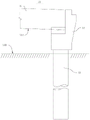
Referring to fig. 1 and fig. 2, in view of the above problems, an embodiment of the present invention provides a bridge span-adding reconstruction device 100, which includes an original bridge platform structure 10 and a reconstruction structure 20. Former bridge platform structure 10 includes former bridge plate 11 and former bridge platform pile foundation 12, rebuilds structure 20 and includes steel-pipe pile 21, adds and strides bridge plate 22, cushion cap structure 23, bearing structure 24 and newly-increased pile foundation 25. The steel pipe pile 21, the original bridge deck pile foundation 12 and the newly added pile foundation 25 are configured to support a bearing platform structure 23 together, the lower end of the support structure 24 is supported by the bearing platform structure 23, and the upper end of the support structure 24 is configured to support the joint of the original bridge deck 11 and the added bridge deck 22.
In the bridge adds to stride reconstruction device 100 of the embodiment of this application, the former abutment pile foundation 12 that has used in former abutment structure 10 carries out the jacking and adds to stride the reconstruction construction, use former abutment pile foundation 12 to combine steel-pipe pile 21, newly-increased pile foundation 25 supports cushion cap structure 23 jointly, set up bearing structure 24 on cushion cap structure 23, use bearing structure 24 as the substructure after rebuilding, with the junction of supporting former bridge plate 11 and adding bridge plate 22. Through this kind of form, the position of bearing structure 24 and newly-increased pile foundation 25 is not restricted to the occupation of land position of former abutment pile foundation 12, and the substructure after the reconstruction is unified with other pier structure outward appearance.
Referring to fig. 1, 2 and 3, the following structures and interconnection relationships of the components of the bridge span erecting device 100 according to the embodiment of the present application are described.
The original bridge plate 11 includes a first joint portion 111 and a first bottom surface 112, the spanning bridge plate 22 includes a second joint portion 221 and a second bottom surface 222, and the first joint portion 111 is used as an end portion of the original bridge plate 11 and is combined with the second joint portion 221, so that the spanning is extended.
In some embodiments of the present application, the bearing platform structure 23 includes a first bearing platform 231 and a second bearing platform 232, the lower end of the first bearing platform 231 is connected to the steel pipe pile 21, the first bearing platform 231 is connected to the second bearing platform 232, the lower end of the second bearing platform 232 is connected to the original bridge platform pile foundation 12 and the newly added pile foundation 25, and the upper end of the second bearing platform 232 is connected to the support structure 24. The first bearing platform 231 comprises a first surface 2311, the second bearing platform 232 comprises a second surface 2321, the normal directions of the first surface 2311 and the second surface 2321 extend along the horizontal direction, the first surface 2311 and the second surface 2321 are butted, and the first bearing platform 231 and the second bearing platform 232 are connected into a whole along the horizontal direction.
By setting the bearing platform structure 23 to include the first bearing platform 231 and the second bearing platform 232, the first bearing platform 231 can be molded by casting first, the first bearing platform 231 is used as a support, the following temporary jacking system 30 is combined to jack the original bridge deck 11 upwards to a calibrated height, a sufficient space is avoided after the pile head 13 of the original bridge platform structure 10 is removed, a newly added pile foundation 25 is arranged, the second bearing platform 232 is molded by casting continuously, and the second bearing platform 232 is used for further arranging the support structure 24, so that construction is facilitated, and implementation is easy.
In other embodiments, the platform structure 23 may be cast at one time.
A foundation pit 520 is excavated around the original bridge abutment pile foundation 12, and the steel pipe pile 21 is driven into the foundation pit 520 by a static pressure process and is used for supporting the first bearing platform 231 of the bearing platform structure 23.
For example, five steel-pipe piles 21 are provided, and the five steel-pipe piles 21 are supported at the lower end of the first bearing platform 231 in a balanced manner.
In some embodiments of the present application, the first bearing platform 231 includes a first steel reinforcement framework 233, the second bearing platform 232 includes a second steel reinforcement framework 234, and the first steel reinforcement framework 233 and the second steel reinforcement framework 234 are integrally connected.
Through this kind of form, can increase the fastness of linking to each other of first cushion cap 231 and second cushion cap 232, make full use of first framework of steel reinforcement 233 of first cushion cap 231 after the construction finishes to increase the bearing capacity of second cushion cap 232, bear bearing structure 24 more reliably.
Referring to fig. 3, in detail, the first steel bar framework 233 includes a plurality of first connecting steel bars 2331, the plurality of first connecting steel bars 2331 protrude from the first surface 2311 in a horizontal direction, the second steel bar framework 234 includes a plurality of second connecting steel bars 2341, the second connecting steel bars 2341 correspond to the first connecting steel bars 2331 one by one, the first connecting steel bars 2331 are connected to the corresponding second connecting steel bars 2341 by using sleeves 235, the sleeves 235 are provided with internal threads, and each connecting steel bar is inserted into one end of the sleeve 235 and is threadedly engaged with the sleeve 235, so that the first steel bar framework 233 and the second steel bar framework 234 are connected into a whole. Further alternatively, the first connecting bar 2331 and the second connecting bar 2341 may be welded together.
In other embodiments, the first reinforcement cage 233 and the second reinforcement cage 234 may be arranged independently of each other, so as to make reasonable use of the construction space in the site and flexibly determine the arrangement positions of the temporary jacking system 30 and the support structure 24 described below.
Optionally, the second steel reinforcement cage 234 is integrally connected to the steel reinforcement cage of the support structure 24 to reinforce the connection strength between the second bearing platform 232 and the support structure 24.
Optionally, the bridge spanning rebuilding apparatus 100 further comprises a temporary jacking system 30, the temporary jacking system 30 being configured to be placed on the first bearing platform 231 and jack the original bridge deck 11 up to the nominal height before the support structure 24 is arranged, and to be removed from the first bearing platform 231 after the support structure 24 is used to support the original bridge deck 11.
Set up in first cushion cap 231 through interim jacking system 30, can use first cushion cap 231 to support interim jacking system 30, avoid in jacking operation process because the foundation subsides to cause former bridge plate 11 jacking back height error great and take place the skew.
For example, the temporary jacking system 30 may be a set of hydraulic jacks or other forms of jacking mechanisms.
In the description of the present application, the position corresponding to the "calibration height" refers to a position slightly higher than the position corresponding to the preset "jacking height" of the original bridge deck 11.
Further, the bridge span-adding reconstruction device 100 further includes a joist structure 40 disposed between the output end of the temporary jacking system 30 and the bottom side (i.e., the first bottom surface 112) of the original bridge deck 11.
Through setting up joist structure 40, the output application of force in the downside of joist structure 40 of interim jacking system 30, the upside of joist structure 40 acts on the first bottom surface 112 of former decking 11, because the intensity of joist structure 40 is higher, and is big with first bottom surface 112 area of contact, can avoid in the jacking process that the first bottom surface 112 of former decking 11 takes place to damage.
Preferably, the gap between the joist structure 40 and the first bottom surface 112 is filled with high-strength cement grout, so as to ensure that the joist structure 40 is entirely horizontal and closely attached to the original bridge deck 11 at the upper part.
The upper surface of the first platform 231 is a third surface 2312, and the upper surface of the second platform 232 is a fourth surface 2322.
In some embodiments of the present application, the third surface 2312 and the fourth surface 2322 are flush with the ground line 510 or are located below the ground line 510.
With this form, it is possible to facilitate burying the bearing platform structure 23 with crushed stones or with earth, etc., reduce corrosion of the bearing platform structure 23 by the external environment, and leave a space above the ground line 510 for arranging other facilities.
In other embodiments, the third surface 2312 and the fourth surface 2322 may also be slightly raised above the ground line 510.
Optionally, the bridge span-adding reconstruction device 100 further comprises a support 26, the support 26 is arranged on the top of the support structure 24, and the support 26 is used for supporting the joint of the original bridge plate 11 and the span-adding bridge plate 22.
The support 26 can further adapt to the gap between the top of the support structure 24 and the original bridge plate 11 and the gap between the top of the support structure and the bridge plate 22, so that the levelness of the original bridge plate 11 and the gap between the top of the support structure and the bridge plate 22 meets the requirement.
For example, the support comprises two bolsters, one supporting the original bridge deck 11 and the other supporting the bridge deck 22.
The embodiment of the present application further provides a bridge, which includes the bridge span rebuilding device 100 in the embodiment of the present application.
The bridge span adding reconstruction device 100 comprises the following reconstruction steps:
referring to fig. 4, the original bridge abutment structure 10 includes an original bridge deck 11, an original bridge abutment pile foundation 12 and a pile head 13;
referring to fig. 5, the bridge site is leveled, a front cone slope of the platform is excavated, a foundation pit 520 is excavated, and the steel pipe pile 21 is statically pressed and welded in the foundation pit 520 in a segmented mode in the vertical direction;
binding a first steel reinforcement framework 233, using a high-strength cement pouring material to pour and mold the first bearing platform 231, and exposing the end of the first connecting steel reinforcement 2331 to the outer side of the first surface 2311 of the first bearing platform 231;
after the first cushion cap 231 is cured and the strength meets the requirement, placing the temporary jacking system 30 on the third surface 2312 of the first cushion cap 231, arranging the joist structure 40 between the output end of the temporary jacking system 30 and the first bottom surface 112 of the original bridge deck 11, and filling a gap between the first bottom surface 112 and the joist structure 40 with high-strength cement grouting material;
referring to fig. 6, the temporary jacking system 30 is used to act on the first bottom surface 112 of the original bridge deck 11 to jack the original bridge deck 11 to a calibrated height, and the temporary jacking system 30 is locked;
removing a capping back wall (not shown in the figure) of the original abutment structure 10, chiseling off a pile head 13 of the original abutment structure 10, avoiding a space for pouring a second bearing platform 232, wherein the height of a longitudinal main rib of an original abutment pile foundation 12 extending out of a pile top is more than or equal to 1m so as to ensure the anchoring length and complete partial removal of the original abutment structure 10;
referring to fig. 7, a newly added pile foundation 25 is erected, a second steel reinforcement framework 234 of a second bearing platform 232 is further bound on the basis of steel reinforcements of the newly added pile foundation 25, and the second steel reinforcement framework 234 and the first steel reinforcement framework 233 are connected into a whole;
pouring the second bearing platform 232, and connecting the steel pipe pile 21, the original bridge platform pile foundation 12, the first bearing platform 231 and the second bearing platform 232 into a whole;
after the strength of the second bearing platform 232 meets the requirement, the supporting structure 24 is cast, and the reconstruction from the bridge abutment structure to the bridge pier structure is completed;
installing a support 26 on the top of the support structure 24, and lowering a temporary jacking system 30 to drop the original bridge plate 11 to a jacking height and support the original bridge plate on the support 26;
the span-added bridge plate 22 is installed in place under the support of an external jacking mechanism, and the span-added bridge plate 22 falls back to the support 26;
referring to fig. 8, the temporary jacking system 30 is removed to complete the span-adding reconstruction;
the foundation pit 520 is backfilled with crushed stone or earth.
The bridge span-adding reconstruction device 100 in the embodiment of the application can further assume that the bridge span plate 22 is added at the end part of the original bridge plate 11, the arrangement positions of the supporting structure 24 and the newly added pile foundation 25 in the reconstruction structure 20 are not limited by the occupied place of the original bridge abutment pile foundation 12, and the reconstructed substructure is uniform in appearance with other bridge pier structures.
It should be noted that the features of the embodiments in the present application may be combined with each other without conflict.
The above description is only a preferred embodiment of the present application and is not intended to limit the present application, and various modifications and changes may be made by those skilled in the art. Any modification, equivalent replacement, improvement and the like made within the spirit and principle of the present application shall be included in the protection scope of the present application.
Claims (9)
1. The utility model provides a bridge adds strides rebuilding device which characterized in that, includes former bridge deck, former bridge platform pile foundation, steel-pipe pile, adds strides the bridge deck, cushion cap structure, bearing structure and newly-increased pile foundation, the steel-pipe pile, former bridge platform pile foundation and newly-increased pile foundation are configured as jointly supporting the cushion cap structure, bearing structure's lower extreme supports in the cushion cap structure, bearing structure's upper end is configured as to support the junction of former bridge deck with add strides the bridge deck.
2. The bridge span-adding rebuilding apparatus of claim 1, wherein the cap structure comprises:
the lower end of the first bearing platform is connected with the steel pipe pile;
the second cushion cap, first cushion cap with the second cushion cap links to each other, the lower extreme of second cushion cap with former bridge platform pile foundation with newly-increased pile foundation links to each other, the upper end of second cushion cap with bearing structure links to each other.
3. The bridge span-adding reconstruction device of claim 2, wherein the first bearing platform and the reinforcement cage of the second bearing platform are connected into a whole.
4. The bridge span-adding reconstruction device of claim 2, wherein the steel reinforcement framework of the second bearing platform is connected with the steel reinforcement framework of the support structure into a whole.
5. The bridge span-adding rebuilding device of claim 2, wherein said bridge span-adding rebuilding device further comprises:
a temporary jacking system configured to be placed on the first bearing platform and jack the original bridge deck to a calibrated height prior to deployment of the support structure, and to be removed from the first bearing platform after supporting the original bridge deck using the support structure.
6. The bridge span-adding rebuilding device of claim 5, wherein said bridge span-adding rebuilding device further comprises:
and the joist structure is arranged between the output end of the temporary jacking system and the bottom side of the original bridge plate.
7. The bridge spanning rebuilding apparatus of claim 1 wherein an upper surface of said cap structure is flush with or below a ground line.
8. The bridge span-adding reconstruction device of claim 1, further comprising:
and the support is arranged at the top of the supporting structure and is used for supporting the joint of the original bridge plate and the spanning bridge plate.
9. A bridge comprising a bridge span reconstruction device according to any one of claims 1 to 8.
Priority Applications (1)
| Application Number | Priority Date | Filing Date | Title |
|---|---|---|---|
| CN202120839129.7U CN216338977U (en) | 2021-04-22 | 2021-04-22 | Bridge is with striding rebuilding device and bridge |
Applications Claiming Priority (1)
| Application Number | Priority Date | Filing Date | Title |
|---|---|---|---|
| CN202120839129.7U CN216338977U (en) | 2021-04-22 | 2021-04-22 | Bridge is with striding rebuilding device and bridge |
Publications (1)
| Publication Number | Publication Date |
|---|---|
| CN216338977U true CN216338977U (en) | 2022-04-19 |
Family
ID=81129257
Family Applications (1)
| Application Number | Title | Priority Date | Filing Date |
|---|---|---|---|
| CN202120839129.7U Active CN216338977U (en) | 2021-04-22 | 2021-04-22 | Bridge is with striding rebuilding device and bridge |
Country Status (1)
| Country | Link |
|---|---|
| CN (1) | CN216338977U (en) |
-
2021
- 2021-04-22 CN CN202120839129.7U patent/CN216338977U/en active Active
Similar Documents
| Publication | Publication Date | Title |
|---|---|---|
| CN102352590B (en) | Method for splicing highfill roadbed by adopting pile-sheet retaining wall | |
| CN109356173A (en) | A kind of pin-connected panel anchor bolt frame girder construction and its construction method | |
| CN108265618B (en) | Underground reverse storey-adding construction method for viaduct pier foundation | |
| CN112095495A (en) | Bridge underpinning support structure and construction method | |
| CN112942147A (en) | Bridge pile active underpinning method | |
| CN104674645A (en) | Integral plate type small bridge and culvert combination applicable to soft soil foundations | |
| CN110158602A (en) | A kind of Soft Clay deep foundation pit support excavation construction structure and construction method | |
| CN106812359B (en) | A kind of assembled underground garage and its method of construction | |
| CN213062136U (en) | Independent foundation underpinning system for storey-adding building | |
| CN216338977U (en) | Bridge is with striding rebuilding device and bridge | |
| CN111705576A (en) | Steep slope high-filling roadbed structure adopting high-density EPS filler | |
| CN116289979A (en) | Deep foundation pit supporting construction method for underground forward and reverse synchronous construction | |
| CN115506382A (en) | Construction method for pile plate wall of island building platform | |
| CN213571600U (en) | Bridge underpins bearing structure | |
| JP4094416B2 (en) | Construction method of multilevel intersection | |
| CN212052780U (en) | Oblique supporting type deep foundation pit supporting structure | |
| CN113266038A (en) | Construction method for excavating underground building in foundation pit | |
| CN110820583B (en) | Cast-in-place box girder support heightening foundation and construction method thereof | |
| CN110777844A (en) | Wall supporting structure based on waste guardrail stand columns and construction method thereof | |
| CN219653491U (en) | Steel construction abutment suitable for steel trestle | |
| CN115404901B (en) | Assembled slurry stirring station foundation and construction method | |
| Marchand | A DEEP BASEMENT IN ALDERSGATE STREET, LONDON. PART 1: CONTRACTOR'S DESIGN AND PLANNING. | |
| CN218713225U (en) | High and steep slope attached platform device | |
| CN217810546U (en) | Bridge foundation lifting type construction platform | |
| CN220433704U (en) | Steel sleeve box device for reinforcing bridge foundation pile lifting |
Legal Events
| Date | Code | Title | Description |
|---|---|---|---|
| GR01 | Patent grant | ||
| GR01 | Patent grant |