CN111705576A - Steep slope high-filling roadbed structure adopting high-density EPS filler - Google Patents
Steep slope high-filling roadbed structure adopting high-density EPS filler Download PDFInfo
- Publication number
- CN111705576A CN111705576A CN202010625499.0A CN202010625499A CN111705576A CN 111705576 A CN111705576 A CN 111705576A CN 202010625499 A CN202010625499 A CN 202010625499A CN 111705576 A CN111705576 A CN 111705576A
- Authority
- CN
- China
- Prior art keywords
- filler
- steep slope
- density eps
- roadbed
- retaining
- Prior art date
- Legal status (The legal status is an assumption and is not a legal conclusion. Google has not performed a legal analysis and makes no representation as to the accuracy of the status listed.)
- Pending
Links
- 239000000945 filler Substances 0.000 title claims abstract description 38
- 239000002689 soil Substances 0.000 claims abstract description 26
- 239000000463 material Substances 0.000 claims abstract description 17
- 239000004576 sand Substances 0.000 claims abstract description 9
- 239000011150 reinforced concrete Substances 0.000 claims description 18
- 239000004567 concrete Substances 0.000 claims description 9
- 230000005484 gravity Effects 0.000 claims description 7
- 238000011065 in-situ storage Methods 0.000 claims description 3
- XLYOFNOQVPJJNP-UHFFFAOYSA-N water Substances O XLYOFNOQVPJJNP-UHFFFAOYSA-N 0.000 claims description 3
- 229920006248 expandable polystyrene Polymers 0.000 abstract description 26
- 238000010276 construction Methods 0.000 abstract description 14
- 230000007613 environmental effect Effects 0.000 abstract 1
- 238000009412 basement excavation Methods 0.000 description 4
- 238000000034 method Methods 0.000 description 3
- 230000003014 reinforcing effect Effects 0.000 description 2
- 239000004575 stone Substances 0.000 description 2
- 241000196324 Embryophyta Species 0.000 description 1
- 238000006424 Flood reaction Methods 0.000 description 1
- 238000004873 anchoring Methods 0.000 description 1
- 238000005452 bending Methods 0.000 description 1
- 239000004566 building material Substances 0.000 description 1
- 230000006835 compression Effects 0.000 description 1
- 238000007906 compression Methods 0.000 description 1
- 230000007547 defect Effects 0.000 description 1
- 238000010586 diagram Methods 0.000 description 1
- 230000000694 effects Effects 0.000 description 1
- 238000009415 formwork Methods 0.000 description 1
- 239000002440 industrial waste Substances 0.000 description 1
- 238000002955 isolation Methods 0.000 description 1
- 238000004519 manufacturing process Methods 0.000 description 1
- 210000003205 muscle Anatomy 0.000 description 1
- 230000002787 reinforcement Effects 0.000 description 1
- 238000000926 separation method Methods 0.000 description 1
- 238000010008 shearing Methods 0.000 description 1
Images


Classifications
-
- E—FIXED CONSTRUCTIONS
- E01—CONSTRUCTION OF ROADS, RAILWAYS, OR BRIDGES
- E01C—CONSTRUCTION OF, OR SURFACES FOR, ROADS, SPORTS GROUNDS, OR THE LIKE; MACHINES OR AUXILIARY TOOLS FOR CONSTRUCTION OR REPAIR
- E01C3/00—Foundations for pavings
-
- E—FIXED CONSTRUCTIONS
- E01—CONSTRUCTION OF ROADS, RAILWAYS, OR BRIDGES
- E01C—CONSTRUCTION OF, OR SURFACES FOR, ROADS, SPORTS GROUNDS, OR THE LIKE; MACHINES OR AUXILIARY TOOLS FOR CONSTRUCTION OR REPAIR
- E01C11/00—Details of pavings
- E01C11/22—Gutters; Kerbs ; Surface drainage of streets, roads or like traffic areas
-
- E—FIXED CONSTRUCTIONS
- E01—CONSTRUCTION OF ROADS, RAILWAYS, OR BRIDGES
- E01C—CONSTRUCTION OF, OR SURFACES FOR, ROADS, SPORTS GROUNDS, OR THE LIKE; MACHINES OR AUXILIARY TOOLS FOR CONSTRUCTION OR REPAIR
- E01C5/00—Pavings made of prefabricated single units
-
- E—FIXED CONSTRUCTIONS
- E01—CONSTRUCTION OF ROADS, RAILWAYS, OR BRIDGES
- E01F—ADDITIONAL WORK, SUCH AS EQUIPPING ROADS OR THE CONSTRUCTION OF PLATFORMS, HELICOPTER LANDING STAGES, SIGNS, SNOW FENCES, OR THE LIKE
- E01F15/00—Safety arrangements for slowing, redirecting or stopping errant vehicles, e.g. guard posts or bollards; Arrangements for reducing damage to roadside structures due to vehicular impact
- E01F15/02—Continuous barriers extending along roads or between traffic lanes
-
- E—FIXED CONSTRUCTIONS
- E02—HYDRAULIC ENGINEERING; FOUNDATIONS; SOIL SHIFTING
- E02D—FOUNDATIONS; EXCAVATIONS; EMBANKMENTS; UNDERGROUND OR UNDERWATER STRUCTURES
- E02D29/00—Independent underground or underwater structures; Retaining walls
- E02D29/02—Retaining or protecting walls
-
- Y—GENERAL TAGGING OF NEW TECHNOLOGICAL DEVELOPMENTS; GENERAL TAGGING OF CROSS-SECTIONAL TECHNOLOGIES SPANNING OVER SEVERAL SECTIONS OF THE IPC; TECHNICAL SUBJECTS COVERED BY FORMER USPC CROSS-REFERENCE ART COLLECTIONS [XRACs] AND DIGESTS
- Y02—TECHNOLOGIES OR APPLICATIONS FOR MITIGATION OR ADAPTATION AGAINST CLIMATE CHANGE
- Y02A—TECHNOLOGIES FOR ADAPTATION TO CLIMATE CHANGE
- Y02A30/00—Adapting or protecting infrastructure or their operation
- Y02A30/60—Planning or developing urban green infrastructure
Abstract
The invention discloses a steep slope high-fill roadbed structure adopting high-density EPS (expandable polystyrene) filler, which comprises short piles, cross beams, upright columns, enlarged foundations, longitudinal connecting beams, bearing plates, soil retaining plates, light filler, sand cushion layers, road surface plates, anti-collision guardrails and side ditches. The invention improves the utilization efficiency of the supporting structure material by reducing the self weight and the soil side pressure of the roadbed filling material, so that the roadbed structure is stressed more reasonably, the structural stability is obviously improved, the volume of the supporting structure is effectively reduced, and the difficult problem of roadbed structure design mainly based on filling in a steep slope high-filling roadbed is effectively solved to a certain extent. The invention has better adaptability to the steep slope terrain in mountainous areas, safe and reliable structure, moderate construction difficulty and good environmental and economic benefits , provides great convenience for the engineering construction in mountainous areas and has popularization and application values in the technical field of highway engineering.
Description
Technical Field
The invention relates to a steep slope high filling roadbed structure, in particular to a roadbed structure which mainly uses filling in a steep slope high filling roadbed and adopts light materials as roadbed filling, and belongs to the technical field of highway engineering.
Background
With the continuous promotion of the construction of the national traffic infrastructure, the construction of the highway continuously extends to the western region, and more high fill roadbed is constructed on the steep slope terrain in the mountainous region. The high fill abrupt slope high fill roadbed not only has poor stability and large construction difficulty, but also has serious influence on the ecological environment.
In order to avoid filling the roadbed at a high steep slope, the bridge-tunnel ratio is generally improved in engineering. Under the same engineering conditions, the construction cost of bridges and tunnels with the same mileage is generally more than 2-3 times of that of roadbeds, so that greater pressure is brought to the construction of traffic lines in western regions which are underdeveloped in economic cost; and the standard requirement of bridge and tunnel specification is very high, and the strict linear requirement and the maximum longitudinal slope limitation are required to be met, so that the construction difficulty is invisibly increased. Therefore, the high subgrade form on the slope of the mountainous area still exists.
For a high-fill roadbed on a slope, at present, a gravity retaining wall, a pile-plate retaining wall, a reinforced retaining wall and the like are mainly adopted in engineering. The supporting scheme has great limitation in treating steep-slope high-fill roadbed. The gravity type retaining wall is mainly guaranteed by the dead weight of the wall body, so that the wall body has a larger section and occupies more land, and the strength performance of the building material cannot be fully exerted; the pile plate type retaining wall is of a cantilever type structure, when the earth is filled in the back of the wall greatly, the cantilever end of the pile is too long, and the shearing force and the bending moment at the boundary of the earth and the stone are large, so the required anchoring section length is longer, the construction has large disturbance to the mountain and the manufacturing cost is higher; the reinforced retaining wall has small self gravity and low cost, but has poor stability, and the instability damage can be caused to the reinforced earth of the abrupt slope subgrade in the mountain area due to the insufficient stability of the reinforced retaining wall, so that the application range of the reinforced retaining wall is limited.
The commonly used roadbed filling material comprises earth stone materials or industrial waste residues, but the application of EPS as the roadbed filling material in a high-filling roadbed or a roadbed structure is not seen in engineering. However, the larger the filling height or the steeper the ground cross slope, the larger the lateral pressure provided by the soil, and the larger the structural section size is required to support the lateral pressure of the soil, resulting in a decrease in the structural efficiency. In addition, the stability and reliability of the retaining structure can be reduced when the soil pressure is too high, and the roadbed instability can even occur under the action of special loads such as earthquakes or floods. The density of the EPS material is only 1% -2% of that of the common road filler, the provided lateral force and dead load are small, the lateral pressure of the filler acting on the supporting structure can be well reduced, and the EPS material has good stability when being used as a roadbed filler.
Disclosure of Invention
The invention aims to solve the defects of the background art, and provides a lightweight structure suitable for a steep slope high filling roadbed by using high-density EPS (expandable polystyrene) as roadbed filling material, so as to solve the problems of overlarge lateral pressure, insufficient structural strength exertion, easy instability of the structure and the like of the traditional roadbed filling material.
In order to achieve the purpose, the invention adopts the technical scheme that:
the utility model provides an adopt abrupt slope height of high density EPS filler to fill roadbed structure which characterized in that: the structure comprises short piles (1), cross beams (2), upright columns (3), an enlarged foundation (4), longitudinal connecting beams (5), bearing plates (6), soil retaining plates (7), light fillers (8), a sand cushion layer (9), road slabs (10), anti-collision guardrails (11) and side ditches (12); the enlarged foundation (4) is buried into a soil body, an upright post (3) is correspondingly arranged on the enlarged foundation (4), the top end of the enlarged foundation (4) is fixedly connected with the bottom end of the corresponding upright post (3), the short pile (1) is obliquely embedded and fixed into a mountain body (13), one end of the cross beam (2) is fixedly connected with the short pile (1), the other end of the cross beam is fixedly connected with the upright post (3), and the short pile (1), the cross beam (2), the upright post (3) and the enlarged foundation (4) form a 'support-retaining' structure in the transverse direction; the supporting-retaining structures are arranged at equal intervals along the longitudinal direction, a longitudinal connecting beam (5) is arranged at the connecting part of the upright post (3) and the cross beam (2), and the supporting-retaining structures are longitudinally connected into a whole by the longitudinal connecting beam (5); the bearing plate (6) is arranged on the cross beam (2), the bearing plate (6) is horizontally aligned with the edge of the cross beam (2), the soil retaining plate (7) is arranged on the inner side of the upright post (3), the bottom end of the soil retaining plate is fixed on the longitudinal connecting beam (5), and the top end of the soil retaining plate is aligned with the top of the upright post (3); the light filler (8) is filled in the space formed by the bearing plate (6), the retaining plate (7) and the slope of the mountain body (13), and the gravity is borne by the lower bearing plate (6); the upper surface of the light filler (8) is provided with a sand cushion layer (9), a pavement slab (10), an anti-collision guardrail (11) and a side ditch (12).
The light filler (8) is made of high-density EPS material, and the density of the high-density EPS material is 50-80kg/m3。
When the high-density EPS building blocks are paved, staggered joints are paved layer by layer from bottom to top, so that continuous joints are avoided.
The short piles (1), the cross beams (2), the upright columns (3) and the longitudinal connecting beams (5) are reinforced concrete structural members with rectangular or circular sections, and the concrete strength grade is not less than C30; the bearing plate (6), the retaining plate (7), the road surface plate (10) and the side ditch (12) are reinforced concrete structural components with rectangular cross sections, and the concrete strength grade is not less than C30; the enlarged foundation (4) and the anti-collision guardrail (11) are reinforced concrete structural members with polygonal cross sections, and the concrete strength grade is not less than C30.
The length of the beam (2) is not more than 8 meters; the longitudinal distance between the upright posts (3) is preferably 4-7 m.
The included angle between the short pile (1) and the cross beam (2) is more than 90 degrees, and the oblique embedding angle of the short pile (1) is perpendicular to the slope of the mountain as much as possible; the embedded depth of the short pile (1) is not less than 3 m, and the specific embedded depth is determined by the mountain soil pressure and the requirement calculation of the vertical bearing capacity of the structure.
And a chamfer is arranged at the junction of the lower parts of the cross beam (2) and the upright post (3) so as to reduce stress concentration of the junction area of the beam and the upright post.
The steep slope high fill subgrade structure adopting the high-density EPS filler is characterized in that: the bearing plates (6) are prefabricated or cast in situ by reinforced concrete, expansion joints are longitudinally arranged between the bearing plates (6), and the width of the expansion joints is not less than 0.02 meter.
The retaining plate (7) is prefabricated or cast in situ by adopting reinforced concrete, a water drainage hole is reserved in the retaining plate, a longitudinal expansion joint is arranged between the retaining plates (7), and the width of the joint is larger than or equal to 0.02 meter.
Due to the adoption of the technical scheme, the invention has the following advantages:
according to the steep slope high-filling roadbed structure adopting the high-density EPS filler, the roadbed structure design problem mainly based on filling in the steep slope high-filling roadbed is effectively solved, the utilization efficiency of the supporting structure is improved by reducing the soil side pressure generated by roadbed filling materials, the roadbed structure is more reasonable in stress, and the structural stability is improved.
The steep slope high-fill roadbed structure adopting the high-density EPS filler adopts the high-density EPS light filler, and has the advantages of ultralight weight, high compression strength, good self-standing property, small lateral deformation, good vibration reduction and isolation effect, simple and convenient construction and the like. The use of lightweight road bed filler can reduce soil lateral pressure and vertical pressure that supporting construction received by a wide margin, improves the stress state of structure, reduces structure cross-sectional dimension to the structure dead weight has been reduced. The adoption of the lightweight roadbed filling material can not only obviously improve the stability of the abrupt slope filling roadbed, but also effectively reduce the volume of the supporting structure.
The steep slope high-filling roadbed structure adopting the high-density EPS filler adopts a light supporting structure, the section of a wall body is smaller, and the stability of the wall is not completely maintained by the self weight, so that the structure is lighter, the masonry amount is saved, the occupied area is less, and the mechanical construction is facilitated.
According to the steep slope high-fill roadbed structure adopting the high-density EPS filler, the gravity center of a wall body is moved backwards by arranging the cross beam (2) in the supporting structure, and the filler on the cross beam (2) is utilized to increase the stability of the wall body, so that the stress distribution of a foundation is more uniform, the material consumption is less than that of a gravity-type retaining wall or a semi-gravity-type retaining wall, and the foundation excavation and backfilling square amount is also greatly reduced.
Drawings
FIG. 1 is a three-dimensional view of the roadbed structure of the invention
Fig. 2 is a side elevation view of the roadbed structure of the present invention
FIG. 3 is a three-dimensional view of the roadbed supporting structure of the present invention
FIG. 4 is a side elevation view of the roadbed supporting structure of the present invention
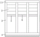
FIG. 5 is a front elevation view of the roadbed supporting structure of the present invention
FIG. 6 is a longitudinal section structure diagram of the roadbed of the present invention
In the figure: 1-short pile, 2-beam, 3-column, 4-enlarged foundation, 5-longitudinal connecting beam, 6-bearing plate, 7-earth retaining plate, 8-light filler, 9-sand cushion layer, 10-road plate, 11-anti-collision guardrail, 12-side ditch and 13-soil body.
Detailed Description
The following detailed description of the embodiments of the present invention will be given in conjunction with the accompanying drawings to make it clear to those skilled in the art how to practice the present invention. While the invention has been described in connection with preferred embodiments thereof, these embodiments are merely illustrative, and not restrictive, of the scope of the invention.
Referring to fig. 1, the steep slope high-fill roadbed structure adopting high-density EPS filler comprises short piles 1, cross beams 2, upright columns 3, an enlarged foundation 4, longitudinal connecting beams 5, a bearing plate 6, a soil retaining plate 7, light filler 8, a sand cushion layer 9, a pavement slab 10, an anti-collision guardrail 11 and a side ditch 12.
During construction, adopting a manual operation method to carry out pile hole excavation on the longitudinal short pile 1, laying a reinforcement cage and a support formwork, and pouring concrete; excavating and pouring the enlarged foundation 4, and placing the enlarged foundation 4 into a firm soil layer to ensure that the enlarged foundation 4 does not generate settlement deformation; the method comprises the following steps that an upright post 3, a cross beam 2 and a longitudinal connecting beam 5 are sequentially poured from bottom to top according to the structure, main ribs are arranged between an enlarged foundation 4 and the upright post 3, between the upright post 3 and the cross beam 2, and between the upright post 3 and the longitudinal connecting beam 5, and are communicated and integrally poured, a short pile 1, the cross beam 2, the upright post 3 and the enlarged foundation 4 transversely form a support-retaining structure, and the longitudinal connecting beam 5 is connected with two adjacent upright posts 3 to enhance the overall stability of the structure; installing a bearing plate 6 and a soil retaining plate 7, wherein the bearing plate 6 and the soil retaining plate 7 respectively bear the gravity and the lateral pressure generated by the upper structure and the filler, and connecting the two adjacent upright columns 3 and the cross beam 2 to enhance the overall stability of the structure; excavating steps along a mountain slope, and paving high-density EPS (expandable polystyrene) building blocks in a staggered joint manner layer by layer from bottom to top so as to avoid generating continuous joints; paving a sand cushion layer 9, pouring a pavement slab 10, an anti-collision guardrail 11 and a side ditch 12.
The above components are generally reinforced concrete structures, and the detailed design such as specific structure, size, reinforcing bars and the like of each component should be calculated and determined according to actual conditions.
One embodiment of the invention
A highway in a certain mountain area is built on a steep slope, the soil body of the slope is a steep slope with the angle of 40 degrees, the height is more than 15 meters, the allowable bearing capacity of a soil foundation is between 250 and 300kpa, and the steep slope high-filling roadbed structure adopting the high-density EPS filler is planned to be adopted.
The embodiment adopts the oblique piles 1 with the rectangular cross sections of 900 multiplied by 900mm according to the scheme of the roadbed structure, the vertical slope surfaces of the oblique piles 1 are embedded and fixed in a mountain, the embedding depth is 4 meters, and the pile hole excavation mode is adopted for the excavation of human working industry.
The enlarged foundation 4 is a strip foundation with the width of 2.4m and the buried depth of 2.8m, the strip foundation is a cast-in-place reinforced concrete member with the strength grade of C40, bears the load transmitted by the superstructure, transmits the load and the dead weight to a firm soil foundation, and cannot generate settlement deformation.
Crossbeam 2, stand 3 is 900 x 900mm rectangular section reinforced concrete component, 3 high 14m of stand, 3 longitudinal separation of stand are 5m, 3 bottom and the bar foundation top fixed connection of stand, 2 one end of crossbeam and the 1 fixed connection of batter pile that long is 7m, the other end and 3 fixed connection of stand, crossbeam 2 sets up the chamfer with the handing-over department of stand 3, the junction of adjacent stand 3 and crossbeam 2 sets up 500 x 500mm rectangular section reinforced concrete vertical tie beam 5, wherein bar foundation 4 and stand 3, stand 3 and crossbeam 2, be the owner muscle to link up and the monolithic concreting between stand 3 and the vertical tie beam 5, vertical tie beam 5 connects the overall stability of adjacent two-upright 3 reinforcing structure.
The bearing plates 6 are arranged on the two adjacent cross beams 2, the bearing plates 6 are horizontally aligned with the edges of the cross beams 2, the bearing plates 6 are cast-in-place reinforced concrete members with the strength grade of C40, seams are longitudinally arranged between the bearing plates, and the seam width is 0.02 m.
The earth-retaining plate is arranged between two adjacent upright posts 3, the bottom of the earth-retaining plate is fixed on the longitudinal connecting beam 2, the top of the earth-retaining plate is parallel and level with the top ends of the upright posts 3, the earth-retaining plate 6 adopts a cast-in-place reinforced concrete member with the strength grade of C40, a water drainage hole is reserved on the plate, a longitudinal expansion joint is arranged between the earth-retaining plates 7, and the width of the joint is 0.02 m.
When the steps are excavated along the mountain slope, weeds on the slope are firstly removed, the steps are excavated along the slope, the height of the steps is 60cm, and a coarse sand cushion layer with the thickness of 10cm is arranged at the contact part of the steps and the EPS block body in consideration of the requirements of construction leveling and drainage.
The density is 50kg/m3The high-density EPS blocks are filled in a space formed by the bearing plate 6, the retaining plate 7 and the slope surface of the mountain 13, and the high-density EPS blocks are paved layer by layer from bottom to top in a staggered manner so as to avoid producing continuous seams.
The method comprises the steps of paving a sand cushion layer 9 on the upper portion of a high-density EPS filler, pouring a pavement slab 10, a side ditch 12 and an anti-collision guardrail 11, wherein the pavement slab 10 and the side ditch 12 are reinforced concrete members with rectangular sections, the concrete strength grade is C40, the anti-collision guardrail 11 is a reinforced concrete member with a polygonal section, and the concrete strength grade is C40.
Claims (9)
1. The utility model provides an adopt abrupt slope height of high density EPS filler to fill roadbed structure which characterized in that: the enlarged foundation (4) is buried in a soil body, an upright post (3) is correspondingly arranged on the enlarged foundation (4), the top end of the enlarged foundation (4) is fixedly connected with the bottom end of the corresponding upright post (3), the short pile (1) is obliquely embedded and fixed in a mountain body (13), one end of the cross beam (2) is fixedly connected with the short pile (1), and the other end of the cross beam is fixedly connected with the upright post (3); the short piles (1), the cross beams (2), the upright posts (3) and the enlarged foundations (4) form a support-retaining structure in the transverse direction; the supporting-retaining structures are arranged at equal intervals along the longitudinal direction; a longitudinal connecting beam (5) is arranged at the joint of the upright column (3) and the cross beam (2), and the longitudinal connecting beam (5) connects the support-retaining structure into a whole in the longitudinal direction; the bearing plate (6) is arranged on the cross beam (2), the bearing plate (6) is horizontally aligned with the edge of the cross beam (2), the soil retaining plate (7) is arranged on the inner side of the upright post (3), the bottom end of the soil retaining plate is fixed on the longitudinal connecting beam (5), and the top end of the soil retaining plate is aligned with the top of the upright post (3); the light filler (8) is filled in the space formed by the bearing plate (6), the retaining plate (7) and the slope of the mountain body (13), and the gravity is borne by the lower bearing plate (6); the upper surface of the light filler (8) is provided with a sand cushion layer (9), a pavement slab (10), an anti-collision guardrail (11) and a side ditch (12).
2. The steep slope high fill structure using high density EPS filler of claim 1, wherein: the light filler(8) Adopts high-density EPS material, the density of the high-density EPS material is 50-80kg/m3。
3. The steep slope high fill subgrade structure adopting the high-density EPS filler is characterized in that: when the high-density EPS building blocks are paved, staggered joints are paved layer by layer from bottom to top, so that continuous joints are avoided.
4. The steep slope high fill subgrade structure adopting the high-density EPS filler is characterized in that: the short piles (1), the cross beams (2), the upright posts (3) and the longitudinal connecting beams (5) are reinforced concrete structural members with rectangular or circular cross sections, and the concrete strength grade is not less than C30; the bearing plate (6), the retaining plate (7), the road surface plate (10) and the side ditch (12) are reinforced concrete structural components with rectangular cross sections, and the concrete strength grade is not less than C30; the enlarged foundation (4) and the anti-collision guardrail (11) are reinforced concrete structural members with polygonal cross sections, and the concrete strength grade is not less than C30.
5. The steep slope high fill subgrade structure adopting the high-density EPS filler is characterized in that: the length of the beam (2) is not more than 8 m; the longitudinal distance between the upright posts (3) is 4-7 m.
6. The steep slope high fill subgrade structure adopting the high-density EPS filler is characterized in that: the included angle between the short pile (1) and the cross beam (2) is more than 90 degrees, and the oblique embedding angle of the short pile (1) is vertical to the slope of the mountain; the embedded depth of the short pile (1) is not less than 3 m, and the specific embedded depth is determined by the mountain soil pressure and the requirement calculation of the vertical bearing capacity of the structure.
7. The steep slope high fill subgrade structure adopting the high-density EPS filler is characterized in that: and a chamfer is arranged at the junction of the lower parts of the cross beam (2) and the upright post (3) so as to reduce stress concentration of the junction area of the beam and the upright post.
8. The steep slope high fill subgrade structure adopting the high-density EPS filler is characterized in that: the bearing plates (6) are prefabricated or cast in situ by reinforced concrete, expansion joints are longitudinally arranged between the bearing plates (6), and the width of the expansion joints is not less than 0.02 meter.
9. The steep slope high fill subgrade structure adopting the high-density EPS filler is characterized in that: the retaining plates (7) are prefabricated or cast in place by adopting reinforced concrete, water drainage holes are reserved in the retaining plates (7), longitudinal expansion joints are arranged between the retaining plates (7), and the joint width is not less than 0.02 meter.
Priority Applications (1)
| Application Number | Priority Date | Filing Date | Title |
|---|---|---|---|
| CN202010625499.0A CN111705576A (en) | 2020-07-01 | 2020-07-01 | Steep slope high-filling roadbed structure adopting high-density EPS filler |
Applications Claiming Priority (1)
| Application Number | Priority Date | Filing Date | Title |
|---|---|---|---|
| CN202010625499.0A CN111705576A (en) | 2020-07-01 | 2020-07-01 | Steep slope high-filling roadbed structure adopting high-density EPS filler |
Publications (1)
| Publication Number | Publication Date |
|---|---|
| CN111705576A true CN111705576A (en) | 2020-09-25 |
Family
ID=72545616
Family Applications (1)
| Application Number | Title | Priority Date | Filing Date |
|---|---|---|---|
| CN202010625499.0A Pending CN111705576A (en) | 2020-07-01 | 2020-07-01 | Steep slope high-filling roadbed structure adopting high-density EPS filler |
Country Status (1)
| Country | Link |
|---|---|
| CN (1) | CN111705576A (en) |
Cited By (2)
| Publication number | Priority date | Publication date | Assignee | Title |
|---|---|---|---|---|
| CN113373750A (en) * | 2021-06-30 | 2021-09-10 | 中铁二院工程集团有限责任公司 | Steep slope high-fill-section roadbed structure and construction method thereof |
| CN115075076A (en) * | 2022-07-20 | 2022-09-20 | 中交第二公路勘察设计研究院有限公司 | High-fill less-soil composite roadbed structure and construction method |
Citations (7)
| Publication number | Priority date | Publication date | Assignee | Title |
|---|---|---|---|---|
| CN203296038U (en) * | 2013-06-05 | 2013-11-20 | 中铁二院重庆勘察设计研究院有限责任公司 | High embankment chair-type sheet-pile retaining wall structure |
| CN203807904U (en) * | 2014-04-02 | 2014-09-03 | 广东省冶金建筑设计研究院 | Lightweight bridgehead roadbed of bubble-mixed lightweight soil and expandable polystyrene (EPS) combined block |
| CN104018405A (en) * | 2014-06-04 | 2014-09-03 | 北京工业大学 | Pile-anchor-frame composite double-layer roadbed structure |
| CN109440558A (en) * | 2018-11-08 | 2019-03-08 | 中铁二院工程集团有限责任公司 | A kind of column foundation anchoring type pallet road structure and its construction method |
| CN110106758A (en) * | 2019-04-15 | 2019-08-09 | 湖北省交通规划设计院股份有限公司 | A kind of prestress type EPS roadbed widening structure and construction method |
| CN110185021A (en) * | 2019-07-10 | 2019-08-30 | 中铁二局第一工程有限公司 | A kind of the compensation subgrade construction structure and method of plastic draining board and CFG soft base changeover portions |
| CN209482075U (en) * | 2019-01-23 | 2019-10-11 | 南京友邦节能材料有限公司 | A kind of embankment structure filled using EPS roadbed plate |
-
2020
- 2020-07-01 CN CN202010625499.0A patent/CN111705576A/en active Pending
Patent Citations (7)
| Publication number | Priority date | Publication date | Assignee | Title |
|---|---|---|---|---|
| CN203296038U (en) * | 2013-06-05 | 2013-11-20 | 中铁二院重庆勘察设计研究院有限责任公司 | High embankment chair-type sheet-pile retaining wall structure |
| CN203807904U (en) * | 2014-04-02 | 2014-09-03 | 广东省冶金建筑设计研究院 | Lightweight bridgehead roadbed of bubble-mixed lightweight soil and expandable polystyrene (EPS) combined block |
| CN104018405A (en) * | 2014-06-04 | 2014-09-03 | 北京工业大学 | Pile-anchor-frame composite double-layer roadbed structure |
| CN109440558A (en) * | 2018-11-08 | 2019-03-08 | 中铁二院工程集团有限责任公司 | A kind of column foundation anchoring type pallet road structure and its construction method |
| CN209482075U (en) * | 2019-01-23 | 2019-10-11 | 南京友邦节能材料有限公司 | A kind of embankment structure filled using EPS roadbed plate |
| CN110106758A (en) * | 2019-04-15 | 2019-08-09 | 湖北省交通规划设计院股份有限公司 | A kind of prestress type EPS roadbed widening structure and construction method |
| CN110185021A (en) * | 2019-07-10 | 2019-08-30 | 中铁二局第一工程有限公司 | A kind of the compensation subgrade construction structure and method of plastic draining board and CFG soft base changeover portions |
Non-Patent Citations (1)
| Title |
|---|
| 金井道夫等: "陡坡上的EPS填筑方法——桩板式面墙法的施工报导", 《路基工程》, 31 October 1992 (1992-10-31), pages 76 - 81 * |
Cited By (3)
| Publication number | Priority date | Publication date | Assignee | Title |
|---|---|---|---|---|
| CN113373750A (en) * | 2021-06-30 | 2021-09-10 | 中铁二院工程集团有限责任公司 | Steep slope high-fill-section roadbed structure and construction method thereof |
| CN113373750B (en) * | 2021-06-30 | 2022-05-24 | 中铁二院工程集团有限责任公司 | Steep slope high-fill-section roadbed structure and construction method thereof |
| CN115075076A (en) * | 2022-07-20 | 2022-09-20 | 中交第二公路勘察设计研究院有限公司 | High-fill less-soil composite roadbed structure and construction method |
Similar Documents
| Publication | Publication Date | Title |
|---|---|---|
| CN105155558A (en) | Combined retaining structure and construction method thereof | |
| CN111305027B (en) | Rapid repairing construction method and repairing structure for subsidence of karst area pavement | |
| CN109403170B (en) | Steep slope road and construction method thereof | |
| CN109750571B (en) | Road collapse emergency and permanent retaining integrated structure and construction method | |
| CN109371989B (en) | A kind of combined type retaining structure and its construction method suitable for stability of slope supporting | |
| CN111705576A (en) | Steep slope high-filling roadbed structure adopting high-density EPS filler | |
| CN114575208A (en) | Abrupt slope roadbed structure convenient to prefabricated installation | |
| CN203334154U (en) | Embankment structure for preventing bearing platform of pile foundation from stretching in roadbed under viaduct | |
| CN111304988A (en) | Light embankment structure built on high and steep hillside and construction method | |
| CN108487234B (en) | Construction method of cast-in-situ pile plate type platform wall | |
| CN112049011B (en) | Reverse construction method for large-span prestressed cast-in-place bridge | |
| CN211922133U (en) | Large cantilever structure suitable for widening old road of cliff road section | |
| CN115506382A (en) | Construction method for pile plate wall of island building platform | |
| CN214882662U (en) | Special roadbed structure above subway | |
| CN212670237U (en) | Repairing structure for subsidence of karst area pavement | |
| CN204940310U (en) | A kind of combination retaining structure | |
| CN113430870A (en) | Roadbed structure for green reinforcement treatment of newly-built railway karst foundation and construction method thereof | |
| CN217324788U (en) | Abrupt slope roadbed structure convenient to prefabrication installation | |
| CN111622035A (en) | Existing road widening and transformation method for reservoir area based on symmetrical integral type overhanging structure | |
| CN114922017B (en) | Newly-built cantilever type retaining wall-existing stake board wall roadbed group wide integrated configuration | |
| CN219793986U (en) | High side slope barricade combination reinforced structure | |
| CN215857760U (en) | Open cut tunnel extension foam concrete backfill structure | |
| CN113308956B (en) | Construction method of pile-supported anchor rod foam concrete embankment structure | |
| CN110424452B (en) | Backfill ceramsite prefabricated reinforced retaining wall structure and construction method | |
| CN219410378U (en) | Rock slope overhanging type road structure |
Legal Events
| Date | Code | Title | Description |
|---|---|---|---|
| PB01 | Publication | ||
| PB01 | Publication | ||
| SE01 | Entry into force of request for substantive examination | ||
| SE01 | Entry into force of request for substantive examination | ||
| RJ01 | Rejection of invention patent application after publication | ||
| RJ01 | Rejection of invention patent application after publication |
Application publication date: 20200925 |