CN216298939U - Polishing treatment device for air spindle of grinding machine - Google Patents
Polishing treatment device for air spindle of grinding machine Download PDFInfo
- Publication number
- CN216298939U CN216298939U CN202122301171.6U CN202122301171U CN216298939U CN 216298939 U CN216298939 U CN 216298939U CN 202122301171 U CN202122301171 U CN 202122301171U CN 216298939 U CN216298939 U CN 216298939U
- Authority
- CN
- China
- Prior art keywords
- polishing
- rectangular
- shaft
- inverted
- shaped
- Prior art date
- Legal status (The legal status is an assumption and is not a legal conclusion. Google has not performed a legal analysis and makes no representation as to the accuracy of the status listed.)
- Active
Links
Images


Abstract
The utility model discloses a polishing treatment device of an air spindle of a grinding machine, which comprises an operating platform, wherein the top of the operating platform is provided with a rotating machine tool chuck, an arc surface polishing device and a plane polishing device which are matched with a fixed shaft, the fixed shaft comprises a shaft rod and a shaft head, the arc surface polishing device comprises a rectangular fixed seat, a rectangular mounting groove, a servo speed reduction motor, a rotating shaft, an I-shaped polishing wheel, a transverse rectangular plate, an inverted L-shaped supporting plate, a hydraulic cylinder, an inverted U-shaped supporting plate and an upper polishing roller, and the plane polishing device comprises a rectangular support, a rectangular concave surface groove in transmission connection with a longitudinal screw rod, a fixed seat, an inverted L-shaped fixed plate, a speed reduction motor, a longitudinal polishing connecting shaft fixedly connected with an output shaft of the speed reduction motor, a polishing cylinder and a motor. The utility model combines the two processes of polishing the outer cambered surface and the front side surface of the upper shaft head of the air spindle into a whole, and polishes the shaft head at one time, thereby effectively improving the polishing efficiency.
Description
Technical Field
The utility model belongs to the technical field of grinding machines, and particularly relates to a polishing treatment device for an air spindle of a grinding machine.
Background
The grinding machine is a grinding machine that grinds the surface of a workpiece with a grinder coated with or embedded with an abrasive. The grinding machine is mainly used for grinding high-precision planes, inner and outer cylindrical surfaces, conical surfaces, spherical surfaces, threaded surfaces and other molded surfaces in workpieces. In the process of processing and producing the air spindle for the grinding machine, in order to improve the appearance and quality of products, a spindle head on a fixed shaft on the air spindle is ground and polished.
When prior art polishes to the epaxial fixed axle of air spindle, the burnishing device who uses has certain limitation, the limitation that polishes to the fixed axle lies in, need divide two processes of polishing to polish the spindle nose, two processes to spindle nose polishing are the extrados polishing and the leading flank polishing of spindle nose, extrados polishing and the leading flank polishing of spindle nose divide into two processes and operate, because can not disposable unite two into one two processes, the direct polishing of spindle nose, not only the inefficiency of polishing, and to the spindle nose conversion, need the manual work, complex operation is in addition, the labour has still been increased.
Therefore, the polishing treatment device of the air spindle of the grinding machine can combine the outer arc surface polishing process and the front side surface polishing process of the spindle head on the air spindle into a whole, directly and once polish the spindle head, effectively improve the polishing efficiency and simplify the operation process.
SUMMERY OF THE UTILITY MODEL
The present invention is directed to a polishing device for an air spindle of a grinding machine, which solves the above problems.
In order to achieve the purpose, the utility model provides the following technical scheme: the utility model provides a grind polishing processing apparatus of machine air spindle, includes the operation panel, the top of operation panel is from the front to the back fixed rotatory lathe chuck, cambered surface burnishing device and the plane burnishing device that is equipped with and air spindle on fixed axle matched with in proper order, the fixed axle includes axostylus axostyle and spindle nose, cambered surface burnishing device includes the rectangle fixing base that fixedly locates the operation panel top and have U-shaped through-hole groove, two rectangle mounting grooves of fixedly locating the rectangle fixing base left and right sides, respectively fix the servo gear motor who locates two inside just of rectangle mounting grooves, respectively with two servo gear motor's output fixed connection and with two pivot that the rectangle fixing base transmission is connected, respectively with two pivot fixed connection and locate two shape polishing wheels of rectangle fixing base leading flank, the symmetry fix in front and back U-shaped through-hole groove top and with two horizontal rectangular plate of rectangle fixing base fixed connection, The plane polishing device comprises a rectangular support fixedly arranged at the top of the operating platform, a rectangular concave groove fixedly arranged at the top of the rectangular support and in transmission connection with a longitudinal screw rod, a fixed seat in transmission connection with the longitudinal screw rod through a screw nut, an inverted L-shaped fixed plate fixedly arranged at the top of the fixed seat, a motor seat fixedly arranged at the top of the inverted L-shaped fixed plate, a speed reducing motor fixedly arranged at the top of the motor seat, and a longitudinal polishing connecting shaft fixedly connected with an output shaft of the speed reducing motor, The polishing cylinder is fixedly connected with the longitudinal polishing connecting shaft, and the motor is fixedly arranged on the rear side face of the rectangular concave groove and is in transmission connection with the input end of the longitudinal screw rod.
Preferably, the rotary machine tool chuck is matched with one end of the shaft lever, which is far away from the shaft head, to be clamped and fixed.
Preferably, the servo motor is fixedly arranged on the rear side surface of the inverted U-shaped support plate.
Preferably, the top of the transverse rectangular plate positioned on the front side is provided with a reinforcing plate fixedly connected with the transverse rectangular plate and the inverted L-shaped support plate.
Preferably, the two I-shaped polishing wheels and one upper polishing roller are matched with the outer arc surface of the shaft head for polishing.
Preferably, the top of the fixed seat is provided with a reinforcing block fixedly connected with the inverted L-shaped fixed plate.
Preferably, the polishing cylinder is matched with the front side surface of the shaft head for polishing.
The utility model has the technical effects and advantages that: the polishing treatment device of the air spindle of the grinding machine comprises a fixed shaft, a shaft lever, a shaft head, a hydraulic cylinder, a motor, a longitudinal lead screw, a fixing seat and a polishing cylinder, wherein the fixed shaft is fixedly clamped on a rotary machine tool chuck, the shaft lever penetrates through a U-shaped through hole groove, the shaft head is attached to the tops of two I-shaped polishing wheels, the rotary machine tool chuck drives the fixed shaft to rotate, a hydraulic rod of the hydraulic cylinder extends to push the upper polishing roller to move downwards to be attached to the shaft head, the upper polishing roller polishes the position, which cannot be polished, of the I-shaped polishing wheels, the upper polishing rollers are matched with the upper polishing rollers to polish the outer arc surface of the shaft head, the motor drives the longitudinal lead screw to transmit, so that the fixing seat and the polishing cylinder are driven to move backwards, the polishing cylinder moves backwards to be attached to the front side surface of the shaft head, the reduction motor drives the polishing cylinder to rotate, the outer side surface of the shaft head is polished in cooperation with the outer arc surface polishing process of the front side surface of the shaft head, the operation process is simplified.
Drawings
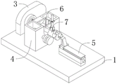
FIG. 1 is a schematic structural view of the present invention;
FIG. 2 is a schematic view of a stationary shaft according to the present invention in a polished state;
FIG. 3 is a schematic view of the fixed shaft of the chuck of the rotary machine tool according to the present invention;
FIG. 4 is a schematic structural diagram of the cambered surface polishing device of the present invention;
FIG. 5 is a schematic view showing the structure of the flat polishing apparatus according to the present invention.
In the figure: 1. an operation table; 2. a fixed shaft; 3. rotating the machine tool chuck; 4. a cambered surface polishing device; 5. a plane polishing device; 6. a shaft lever; 7. a shaft head; 8. a U-shaped through-hole slot; 9. a rectangular fixed seat; 10. a rectangular mounting groove; 11. a servo deceleration motor; 12. a rotating shaft; 13. an I-shaped polishing wheel; 14. a transverse rectangular plate; 15. an inverted L-shaped support plate; 16. a hydraulic cylinder; 17. an inverted U-shaped support plate; 18. a servo motor; 19. an upper polishing roll; 20. a reinforcing plate; 21. a rectangular support; 22. a longitudinal screw rod; 23. a rectangular concave groove; 24. a fixed seat; 25. an inverted L-shaped fixing plate; 26. a motor base; 27. a reduction motor; 28. longitudinally polishing the connecting shaft; 29. polishing the cylinder; 30. a motor; 31. and a reinforcing block.
Detailed Description
The technical solutions in the embodiments of the present invention will be clearly and completely described below with reference to the drawings in the embodiments of the present invention, and it is obvious that the described embodiments are only a part of the embodiments of the present invention, and not all of the embodiments. All other embodiments, which can be derived by a person skilled in the art from the embodiments given herein without making any creative effort, shall fall within the protection scope of the present invention.
The utility model provides a polishing treatment device of an air spindle of a grinding machine, which comprises an operating table 1, wherein a rotary machine tool chuck 3, an arc surface polishing device 4 and a plane polishing device 5 which are matched with a fixed shaft 2 on the air spindle are sequentially and fixedly arranged at the top of the operating table 1 from front to back, the fixed shaft 2 comprises a shaft lever 6 and a shaft head 7, and the rotary machine tool chuck 3 is matched with one end of the shaft lever 6, which is far away from the shaft head 7, to be clamped and fixed;
the shaft lever 6 is clamped and fixed by the rotary machine tool chuck 3, and when the fixed shaft 2 is polished, the fixed shaft 2 can be driven to rotate under the action of the rotary machine tool chuck 3;
the cambered surface polishing device 4 comprises a rectangular fixed seat 9 which is fixedly arranged at the top of the operating platform 1 and is provided with a U-shaped through hole groove 8, two rectangular mounting grooves 10 which are fixedly arranged at the left side and the right side of the rectangular fixed seat 9, servo reducing motors 11 which are respectively and fixedly arranged in the two rectangular mounting grooves 10, two rotating shafts 12 which are respectively and fixedly connected with the output ends of the two servo reducing motors 11 and are in transmission connection with the rectangular fixed seat 9, two I-shaped polishing wheels 13 which are respectively and fixedly connected with the two rotating shafts 12 and are arranged at the front side of the rectangular fixed seat 9, two transverse rectangular plates 14 which are symmetrically and fixedly arranged at the top of the U-shaped through hole groove 8 in the front-back direction and are fixedly connected with the rectangular fixed seat 9, an inverted L-shaped support plate 15 which is fixedly connected with the transverse rectangular plate 14 positioned at the front side, a hydraulic cylinder 16 which is fixedly arranged at the top of the inverted L-shaped support plate 15, an inverted U-shaped support plate 17 which is fixedly connected with a hydraulic rod on the hydraulic cylinder 16 and is arranged below the inverted L-shaped support plate 15, The upper polishing roller 19 is arranged on the inner side of the inverted U-shaped support plate 17 in a transmission mode, the output end of the servo motor 18 is connected with the upper polishing roller 19 in a transmission mode, the spindle nose 7 is arranged above the two I-shaped polishing wheels 13 and limited at the bottom of the upper polishing roller 19, the servo motor 18 is fixedly arranged on the rear side face of the inverted U-shaped support plate 17, a reinforcing plate 20 fixedly connected with the transverse rectangular plate 14 and the inverted L-shaped support plate 15 is arranged at the top of the transverse rectangular plate 14 located on the front side, and the two I-shaped polishing wheels 13 and one upper polishing roller 19 are matched with the outer arc face of the spindle nose 7 for polishing;
after the fixed shaft 2 is fixedly clamped on a chuck 3 of a rotary machine tool, the shaft lever 6 penetrates through the U-shaped through hole groove, the shaft head 7 is attached to the tops of two I-shaped polishing wheels 13, a hydraulic rod of a hydraulic cylinder 16 extends to push an upper polishing roller 19 to move downwards to be attached to the shaft head 7, the upper polishing roller 19 is used for polishing positions, which cannot be polished, on the I-shaped polishing wheels 13, and the I-shaped polishing wheels 13 and the upper polishing roller 19 are matched to polish and polish the outer arc surfaces of the shaft head 7;
the plane polishing device 5 comprises a rectangular support 21 fixedly arranged at the top of the operating platform 1, a rectangular concave groove 23 fixedly arranged at the top of the rectangular support 21 and in transmission connection with a longitudinal screw rod 22, a fixed seat 24 in transmission connection with the longitudinal screw rod 22 through a screw nut, an inverted L-shaped fixed plate 25 fixedly arranged at the top of the fixed seat 24, a motor seat 26 fixedly arranged at the top of the inverted L-shaped fixed plate 25, a speed reducing motor 27 fixedly arranged at the top of the motor seat 26, a longitudinal polishing connecting shaft 28 fixedly connected with an output shaft of the speed reducing motor 27, a polishing cylinder 29 fixedly connected with the longitudinal polishing connecting shaft 28 and a motor 30 fixedly arranged on the rear side surface of the rectangular concave groove 23 and in transmission connection with an input end of the longitudinal screw rod 22, the top of the fixed seat 24 is provided with a reinforcing block 31 fixedly connected with the fixed seat and the inverted L-shaped fixing plate 25, and the polishing cylinder 29 is matched with the front side surface of the shaft head 7 for polishing;
the motor 30 drives the longitudinal screw rod 22 to drive, so that the fixing seat 24 and the polishing cylinder 29 are driven to move backwards, the polishing cylinder 29 moves backwards to be attached to the front side face of the spindle head 7 and the front side face of the spindle head 7, the speed reduction motor 27 drives the polishing cylinder 29 to rotate, and the outer side face of the spindle head 7 is polished in cooperation with the rotating spindle head 7;
the two processes of polishing the outer arc surface of the shaft head 7 and polishing the front side surface of the shaft head 7 can be combined into one, the shaft head 7 is directly polished at one time, the polishing efficiency can be effectively improved, the operation process is simplified, and the machining efficiency of the air spindle is improved.
Finally, it should be noted that: although the present invention has been described in detail with reference to the foregoing embodiments, it will be apparent to those skilled in the art that modifications may be made to the embodiments or portions thereof without departing from the spirit and scope of the utility model.
Claims (7)
1. A polishing treatment device of an air spindle of a grinding machine comprises an operation table (1), and is characterized in that: the top of the operating platform (1) is fixedly provided with a rotary machine tool chuck (3), an arc surface polishing device (4) and a plane polishing device (5) which are matched with the fixed shaft (2) on the air spindle from front to back, and the fixed shaft (2) comprises a shaft lever (6) and a shaft head (7);
the cambered surface polishing device (4) comprises a rectangular fixing seat (9) which is fixedly arranged at the top of an operation table (1) and is provided with a U-shaped through hole groove (8), two rectangular mounting grooves (10) which are fixedly arranged at the left side and the right side of the rectangular fixing seat (9), servo reducing motors (11) which are respectively and fixedly arranged inside the two rectangular mounting grooves (10), two rotating shafts (12) which are respectively and fixedly connected with the output ends of the two servo reducing motors (11) and are in transmission connection with the rectangular fixing seat (9), two I-shaped polishing wheels (13) which are respectively and fixedly connected with the two rotating shafts (12) and are arranged at the front side of the rectangular fixing seat (9), two transverse rectangular plates (14) which are symmetrically and fixedly arranged at the top of the U-shaped through hole groove (8) and are fixedly connected with the rectangular fixing seat (9) in the front and back direction, and an inverted L-shaped support plate (15) which is fixedly connected with the transverse rectangular plate (14) positioned at the front side, The polishing machine comprises a hydraulic cylinder (16) fixedly arranged at the top of an inverted L-shaped support plate (15), an inverted U-shaped support plate (17) fixedly connected with a hydraulic rod on the hydraulic cylinder (16) and arranged below the inverted L-shaped support plate (15), and an upper polishing roller (19) which is arranged on the inner side of the inverted U-shaped support plate (17) in a transmission manner and is in transmission connection with the output end of a servo motor (18), wherein a shaft head (7) is arranged above two I-shaped polishing wheels (13) and is limited at the bottom of the upper polishing roller (19);
the plane polishing device (5) comprises a rectangular support (21) fixedly arranged at the top of the operating platform (1), a rectangular concave groove (23) fixedly arranged at the top of the rectangular support (21) and in transmission connection with a longitudinal screw rod (22), a fixing seat (24) in transmission connection with the longitudinal screw rod (22) through a screw nut, an inverted L-shaped fixing plate (25) fixedly arranged at the top of the fixing seat (24), a motor seat (26) fixedly arranged at the top of the inverted L-shaped fixing plate (25), a speed reducing motor (27) fixedly arranged at the top of the motor seat (26), a longitudinal polishing connecting shaft (28) fixedly connected with an output shaft of the speed reducing motor (27), a polishing cylinder (29) fixedly connected with the longitudinal polishing connecting shaft (28) and a motor (30) fixedly arranged at the rear side face of the rectangular concave groove (23) and in transmission connection with an input end of the longitudinal screw rod (22).
2. A polishing treatment device of an air spindle of a grinder according to claim 1, characterized in that: the rotary machine tool chuck (3) is matched with one end of the shaft lever (6) far away from the shaft head (7) to be clamped and fixed.
3. A polishing treatment device of an air spindle of a grinder according to claim 1, characterized in that: the servo motor (18) is fixedly arranged on the rear side surface of the inverted U-shaped support plate (17).
4. A polishing treatment device of an air spindle of a grinder according to claim 1, characterized in that: and a reinforcing plate (20) fixedly connected with the transverse rectangular plate (14) and the inverted L-shaped support plate (15) is arranged at the top of the transverse rectangular plate (14) on the front side.
5. A polishing treatment device of an air spindle of a grinder according to claim 1, characterized in that: the two I-shaped polishing wheels (13) and an upper polishing roller (19) are matched with the outer arc surface of the shaft head (7) for polishing.
6. A polishing treatment device of an air spindle of a grinder according to claim 1, characterized in that: the top of the fixed seat (24) is provided with a reinforcing block (31) fixedly connected with the inverted L-shaped fixed plate (25).
7. A polishing treatment device of an air spindle of a grinder according to claim 1, characterized in that: the polishing cylinder (29) is matched with the front side surface of the shaft head (7) for polishing.
Priority Applications (1)
| Application Number | Priority Date | Filing Date | Title |
|---|---|---|---|
| CN202122301171.6U CN216298939U (en) | 2021-09-23 | 2021-09-23 | Polishing treatment device for air spindle of grinding machine |
Applications Claiming Priority (1)
| Application Number | Priority Date | Filing Date | Title |
|---|---|---|---|
| CN202122301171.6U CN216298939U (en) | 2021-09-23 | 2021-09-23 | Polishing treatment device for air spindle of grinding machine |
Publications (1)
| Publication Number | Publication Date |
|---|---|
| CN216298939U true CN216298939U (en) | 2022-04-15 |
Family
ID=81111536
Family Applications (1)
| Application Number | Title | Priority Date | Filing Date |
|---|---|---|---|
| CN202122301171.6U Active CN216298939U (en) | 2021-09-23 | 2021-09-23 | Polishing treatment device for air spindle of grinding machine |
Country Status (1)
| Country | Link |
|---|---|
| CN (1) | CN216298939U (en) |
-
2021
- 2021-09-23 CN CN202122301171.6U patent/CN216298939U/en active Active
Similar Documents
| Publication | Publication Date | Title |
|---|---|---|
| CN216179344U (en) | Polishing equipment based on mechanical polishing | |
| CN215357869U (en) | Piston rod excircle polishing machine | |
| CN216298939U (en) | Polishing treatment device for air spindle of grinding machine | |
| CN2920538Y (en) | Automatic reseator of hobbing cutter precision grinding abrasive disk | |
| CN210588647U (en) | Multi-station multi-degree-of-freedom workpiece polishing device | |
| CN114603445B (en) | Automatic control type grinding integrated device based on shaft side machining | |
| CN207983040U (en) | A kind of tank body sanding and polishing equipment | |
| CN110539234A (en) | slender shaft polishing device | |
| CN2843743Y (en) | Four main cone double-ended grinding machine | |
| CN215547269U (en) | Cylindrical grinder capable of automatically feeding and discharging | |
| CN206123343U (en) | Two grindstone head cylindrical grinders | |
| CN214025036U (en) | Jade polisher | |
| CN210818845U (en) | Casting polishing device | |
| CN113635189A (en) | Surface polishing and grinding system for forging and casting and machining process | |
| CN208409254U (en) | A kind of CNC milling machine batch clamping mechanism easy to use | |
| CN110340760A (en) | A kind of construction sanding and polishing equipment | |
| CN219599034U (en) | Multi-station five-axis numerical control grinding and polishing machine | |
| CN212265468U (en) | Polisher with powerful grinding function | |
| CN114012517B (en) | High efficiency cylindrical grinder auxiliary device | |
| CN210732050U (en) | Double-grinding-head shaft abrasive belt machine | |
| CN211305826U (en) | Edge bonding machine mills device in advance | |
| CN208744493U (en) | A kind of reciprocating sander | |
| CN213673190U (en) | Diamond edging machine side edging mechanism | |
| CN213673402U (en) | Double-end abrasive band machine is used in die-casting machine tooling | |
| CN211615208U (en) | Grinding wheel grinding tool of high-precision grinding machine |
Legal Events
| Date | Code | Title | Description |
|---|---|---|---|
| GR01 | Patent grant | ||
| GR01 | Patent grant |