CN216133508U - Overspeed snapshot device - Google Patents
Overspeed snapshot device Download PDFInfo
- Publication number
- CN216133508U CN216133508U CN202121182695.1U CN202121182695U CN216133508U CN 216133508 U CN216133508 U CN 216133508U CN 202121182695 U CN202121182695 U CN 202121182695U CN 216133508 U CN216133508 U CN 216133508U
- Authority
- CN
- China
- Prior art keywords
- probe
- overspeed
- radar
- camera
- shell
- Prior art date
- Legal status (The legal status is an assumption and is not a legal conclusion. Google has not performed a legal analysis and makes no representation as to the accuracy of the status listed.)
- Active
Links
Images


Abstract
The utility model relates to the field of traffic management and discloses an overspeed snapshot device which comprises a first probe, a second probe, an angle adjusting structure, a shell, a camera, a radar velocimeter, a night light supplement lamp and a controller, wherein the first probe is connected with the second probe through a cable; the angle adjusting structure is arranged in the shell, the first probe and the second probe are arranged on the angle adjusting structure, and two openings are formed in the side surface of the shell; the one end that angle modulation structure was kept away from to first probe and second probe all is provided with camera and night light filling lamp, sets up on the radar tachymeter on first probe. Through the arrangement of the technical scheme, the first probe and the second probe face the coming direction and the going direction of a road respectively, and the cameras can shoot from the front direction and the rear direction of a vehicle at the same time, so that the situation that the motorcycle and the vehicle with the front license plate shielded are difficult to obtain evidence is avoided; the angle adjusting structure can adjust the included angle between the first probe and the second probe, and ensures that a shooting picture of the camera contains more road information as far as possible.
Description
Technical Field
The utility model relates to the field of traffic management, in particular to an overspeed snapshot device.
Background
With the increasing living standard of people, more and more people already have private cars, and great convenience is provided for going out and going far away. However, the number of deaths caused by traffic accidents is continuously increased every year, and according to the incomplete statistics of relevant departments on the traffic accidents on expressways, more than 80% of traffic accidents are caused by overspeed driving.
In order to effectively restrain the violation and overspeed behaviors of vehicles on roads, traffic management departments in various regions increase the attack force on the violation and overspeed vehicles, and rely on advanced high-tech means to carry out speed measurement, evidence obtaining and registration on the overspeed vehicles and heavily penalize the violation and overspeed vehicles. At present, in the actual law enforcement process, the front license plate of a part of vehicles is covered by dust, the license plate number cannot be seen clearly, or the motorcycle is hung on the tail of the vehicle for taking a picture, and the current vehicle velometer widely used on the highway comprises an LED vehicle speed display screen and a fixed high-definition snapshot system, wherein the fixed high-definition snapshot system is provided with a camera and a flash lamp which are oriented towards the vehicle direction, the vehicle velometer can only take a picture and obtain evidence in front of the vehicle in the road coming direction, and the rear license plate number of the vehicle cannot be shot clearly, so that the traffic law enforcement difficulty is caused.
SUMMERY OF THE UTILITY MODEL
The utility model aims to provide an overspeed snapshot device, which can solve the problem that the prior art can not shoot and obtain evidence for vehicles with unclear or no front license plates.
In order to achieve the purpose, the utility model provides an overspeed snapshot device, which comprises a first probe, a second probe, an angle adjusting structure, a shell, a camera, a radar velocimeter, a night light supplement lamp and a controller, wherein the first probe is connected with the second probe; the shell is of an internal hollow structure, the angle adjusting structure is arranged in the shell, the first probe and the second probe are rotatably arranged on the angle adjusting structure, two openings which are respectively suitable for the rotation actions of the first probe and the second probe are arranged on the side surface of the shell, and the first probe and the second probe respectively penetrate through the openings and face towards two different angles; first probe and second probe are kept away from the one end of angle modulation structure all is provided with camera and light filling lamp at night, set up on the radar tachymeter on first probe, camera, radar tachymeter, light filling lamp at night are connected with the controller electricity.
Through the arrangement of the technical scheme, the first probe and the second probe face the coming direction and the going direction of a road respectively, and the cameras can shoot from the front direction and the rear direction of a vehicle at the same time, so that the situation that the motorcycle and the vehicle with the front license plate shielded are difficult to obtain evidence is avoided; the angle adjusting structure can adjust the included angle between the first probe and the second probe, and ensures that a shooting picture of the camera contains more road information as far as possible.
Further, angle modulation structure includes center pin, two sleeves, two fixed arms, the center pin is fixed to be set up in the shell, the sleeve rotatably overlaps to be established on the center pin, two fixed arm one end respectively with two telescopic circumference surface fixed connection, two the other end of fixed arm respectively with first probe, second probe fixed connection.
Further, the overspeed snapshot device further comprises a dustproof structure, the dustproof structure comprises sliding grooves, two baffles and rubber connecting blocks, the sliding grooves are formed in two sides of the opening, the baffles are movably arranged in the sliding grooves, and the baffles are fixedly connected with the first probe through the rubber connecting blocks.
Further, the surface of shell is provided with the display screen, the display screen is connected with the controller electricity.
Further, the radar velocimeter comprises:
the radar beam transmitter is used for transmitting radar beams to the direction of the coming vehicles on the road;
the radar beam receiver is used for receiving the echo reflected by the motor vehicle;
and the radar beam analyzer is used for analyzing the reflected echo, measuring the speed of the vehicle, and starting a photographing instruction when detecting that the overspeed of the vehicle exceeds the limited maximum speed.
Further, the controller includes:
the video processing module is used for processing the images shot by the camera;
the storage module is used for storing the processed image;
the remote communication module is used for transmitting the image in the storage module to a monitoring center so as to record the motor vehicle violating the regulations;
the power module is used for providing power for the camera, the radar speed measuring instrument and the night light supplementing lamp, and the power module is connected with a mains supply plug through a wire.
Further, the overspeed snapshot device further comprises a support structure, and the support structure is connected with the bottom surface of the shell.
Furthermore, the supporting structure comprises a supporting column and a supporting chassis, the supporting column is fixedly connected with the bottom surface of the shell, and the supporting chassis is fixedly connected with the bottom surface of the supporting column.
Further, the support structure is a tripod.
Additional features and advantages of the utility model will be set forth in the detailed description which follows.
Drawings
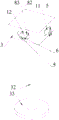
FIG. 1 is a schematic structural diagram of an embodiment of the present invention;
FIG. 2 is a schematic diagram of another perspective of an embodiment of the present invention;
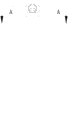
FIG. 3 is a front view of the present invention;
FIG. 4 is a cross-sectional view taken along A-A of FIG. 3;
fig. 5 is a schematic structural view of the angle adjusting structure.
Description of the reference numerals
11 first probe 22 sleeve
12 second Probe 23 fixed arm
3 sliding groove of housing 81
4 camera 82 baffle
82 rubber connecting block of 5 radar speed measuring instrument
6 light filling lamp 9 display screen at night
7 controller 32 support column
31 opening 33 support chassis
21 center shaft
Detailed Description
The following describes in detail specific embodiments of the present invention. It should be understood that the detailed description and specific examples, while indicating the present invention, are given by way of illustration and explanation only, not limitation.
In the present invention, the use of the terms of orientation such as "upper and lower" in the case where no description is made to the contrary generally means the orientation in the assembled and used state. "inner and outer" refer to the inner and outer contours of the respective component itself.
The utility model provides an overspeed snapshot device, which comprises a first probe 11, a second probe 12, an angle adjusting structure, a shell 3, a camera 4, a radar velocimeter 5, a night light supplement lamp 6 and a controller 7, wherein the first probe and the second probe are respectively connected with the first probe and the second probe through a connecting rod; the shell 3 is a hollow structure, the angle adjusting structure is arranged in the shell 3, the first probe 11 and the second probe 12 are rotatably mounted on the angle adjusting structure, two openings 31 which are respectively adapted to the rotation of the first probe 11 and the second probe 12 are arranged on the side surface of the shell 3, and the first probe 11 and the second probe 12 respectively pass through the openings 31 and face two different angles; first probe 11 and second probe 12 are kept away from the one end of angle modulation structure all is provided with camera 4 and night light filling lamp 6, set up on first probe 11 on radar tachymeter 5, camera 4, radar tachymeter 5, night light filling lamp 6 are connected with controller 6 electricity.
Through the arrangement of the technical scheme, the first probe 11 and the second probe 12 respectively face the direction of the coming vehicle and the direction of the going vehicle on the road, and the camera 4 can shoot from the front and back directions of the vehicle at the same time, so that the situation that the motorcycle and the vehicle with the front license plate shielded are difficult to obtain evidence is avoided; the angle adjusting structure can adjust the included angle between the first probe 11 and the second probe 12, and ensure that the shot picture of the camera 4 contains more road information as much as possible.
It should be noted that the radar velocimeter 5 detects an overspeed signal by the shooting of the camera 4 and the turning on of the night light supplement lamp 6. Wherein, in order to confirm the scene that light filling lamp 6 carries out the light filling at night need be opened, still there is light sensor on the shell 3, light sensor with controller 7 electricity is connected.
In order to enable the angle of the first probe 11 and the second probe 12 to be adjusted, preferably, as shown in fig. 5, the angle adjusting structure 2 includes a central shaft 21, two sleeves 22, and two fixing arms 23, wherein the central shaft 21 is fixedly disposed in the housing 3, the two sleeves 22 are rotatably sleeved on the central shaft 21 one above the other, one end of each of the two fixing arms 23 is fixedly connected to the circumferential surface of each of the two sleeves 22, and the other end of each of the two fixing arms 23 is fixedly connected to the first probe 11 and the second probe 12. Preferably, the sleeve 22 is bearing-connected to the central shaft 21.
Because the dust is more rolled up by the vehicle on the road, and road environment is also comparatively complicated, in order to ensure the cleanness of spare part in the shell 3, block the dust and get into, under preferred circumstances, overspeed snapshot device still includes dustproof construction, dustproof construction includes sliding tray 81, two baffles 82, rubber connecting block 83, sliding tray 81 sets up the both sides of opening 31, baffle 82 is movably set up in affiliated sliding tray 81, baffle 82 pass through rubber connecting block 83 with first probe 81 fixed connection. Through the arrangement of the technical scheme, the baffle 82 and the rubber connecting block 83 have the effect of preventing dust from entering the shell 3; the movable baffle 82 can move along with the first probe 11 and the second probe 12 under the condition that the angles of the two probes are adjusted; the rubber connecting block 83 can be bent to prevent the interference of the circular motion of the first and second probes 11 and 12 and the linear motion of the shutter 82.
In order to observe the image shot by the camera 4 as the basis for adjusting the angles of the first probe 11 and the second probe 12, a display 9 is preferably arranged on the outer surface of the housing 3, and the display 9 is electrically connected with the controller 7. The display screen 9 displays a picture shot by the camera 4. Preferably, the display screen 9 is arranged on the side surface of the shell 3 opposite to the first probe 11, so that an operator can observe vehicles in the direction of the coming vehicle at the same time when observing a picture, and the accidental accident is prevented from injuring the operator.
Further, the radar velocimeter comprises:
the radar beam transmitter is used for transmitting radar beams to the direction of the coming vehicles on the road;
the radar beam receiver is used for receiving the echo reflected by the motor vehicle;
and the radar beam analyzer is used for analyzing the reflected echo, measuring the speed of the vehicle, and starting a photographing instruction when detecting that the overspeed of the vehicle exceeds the limited maximum speed.
Wherein the controller 7 includes:
the video processing module is used for processing the images shot by the camera 4;
the storage module is used for storing the processed image;
the remote communication module is used for transmitting the image in the storage module to a monitoring center so as to record the motor vehicle violating the regulations;
the power module is used for providing power for the camera 4, the radar speed measuring instrument 5 and the night light supplementing lamp 6, and the power module is connected with a mains supply plug through a wire.
In order to increase the height of the first probe 11 and the second probe 12, the overspeed snap shot apparatus preferably further comprises a support structure connected to the bottom surface of the housing 3.
As a first embodiment, the supporting structure includes a supporting column 32 and a supporting chassis 33, the supporting column 32 is fixedly connected with the bottom surface of the housing 1, and the supporting chassis 33 is fixedly connected with the bottom surface of the supporting column 32. In this embodiment, the support structure has a large mass and a stable support effect.
As a second embodiment, the support structure is a tripod. In this embodiment, the support structure can be applied to a wide range of terrain and can be adapted to uneven road surfaces.
The preferred embodiments of the present invention have been described in detail, however, the present invention is not limited to the specific details of the above embodiments, and various simple modifications may be made to the technical solution of the present invention within the technical idea of the present invention, and these simple modifications are within the protective scope of the present invention.
It should be noted that the various features described in the above embodiments may be combined in any suitable manner without departing from the scope of the utility model. The utility model is not described in detail in order to avoid unnecessary repetition.
In addition, any combination of the various embodiments of the present invention is also possible, and the same should be considered as the disclosure of the present invention as long as it does not depart from the spirit of the present invention.
Claims (9)
1. An overspeed snapshot device is characterized by comprising a first probe (11), a second probe (12), an angle adjusting structure, a shell (3), a camera (4), a radar velocimeter (5), a night light supplement lamp (6) and a controller (7); the shell (3) is of an internal hollow structure, the angle adjusting structure is arranged in the shell (3), the first probe (11) and the second probe (12) are rotatably mounted on the angle adjusting structure, two openings (31) which are respectively suitable for the rotation action of the first probe (11) and the second probe (12) are formed in the side surface of the shell (3), and the first probe (11) and the second probe (12) respectively penetrate through the openings (31) and face towards two different angles; keep away from first probe (11) and second probe (12) the one end of angle modulation structure all is provided with camera (4) and night light filling lamp (6), set up on radar tachymeter (5) on first probe (11), camera (4), radar tachymeter (5), night light filling lamp (6) are connected with controller (7) electricity.
2. The overspeed snapshot device of claim 1, wherein the angle adjustment structure (2) comprises a central shaft (21), two sleeves (22), and two fixing arms (23), the central shaft (21) is fixedly disposed in the housing (3), the sleeves (22) are rotatably sleeved on the central shaft (21), one end of each of the two fixing arms (23) is fixedly connected to the circumferential surfaces of the two sleeves (22), and the other end of each of the two fixing arms (23) is fixedly connected to the first probe (11) and the second probe (12).
3. The overspeed snapshot apparatus of claim 1, further comprising a dustproof structure, wherein the dustproof structure comprises a sliding groove (81), two baffles (82) and a rubber connecting block (83), the sliding groove (81) is arranged on two sides of the opening (31), the baffles (82) are movably arranged in the sliding groove (81), and the baffles (82) are fixedly connected with the first probe (11) through the rubber connecting block (83).
4. Overspeed snapshot arrangement in accordance with claim 1, characterized in that the outer surface of the housing (3) is provided with a display screen (9), which display screen (9) is electrically connected to the controller (7).
5. The overspeed snapshot apparatus of claim 1 wherein said radar velocimeter comprises:
the radar beam transmitter is used for transmitting radar beams to the direction of the coming vehicles on the road;
the radar beam receiver is used for receiving the echo reflected by the motor vehicle;
and the radar beam analyzer is used for analyzing the reflected echo, measuring the speed of the vehicle, and starting a photographing instruction when detecting that the overspeed of the vehicle exceeds the limited maximum speed.
6. The overspeed snapping arrangement of claim 1 wherein said controller (7) comprises:
the video processing module is used for processing the images shot by the camera (4);
the storage module is used for storing the processed image;
the remote communication module is used for transmitting the image in the storage module to a monitoring center so as to record the motor vehicle violating the regulations;
the power module is used for providing power for the camera (4), the radar speed measuring instrument (5) and the night light supplement lamp (6), and the power module is connected with a mains supply plug through a wire.
7. The overspeed device snap-shot of claim 1 characterized in that it further comprises a support structure connected with the bottom surface of the housing (3).
8. The overspeed snapshot apparatus of claim 7, wherein the support structure comprises a support column (32), a support chassis (33), the support column (32) being fixedly connected to a bottom surface of the housing (3), the support chassis (33) being fixedly connected to a bottom surface of the support column (32).
9. The overspeed snapshot apparatus of claim 7 wherein said support structure is a tripod.
Priority Applications (1)
| Application Number | Priority Date | Filing Date | Title |
|---|---|---|---|
| CN202121182695.1U CN216133508U (en) | 2021-05-28 | 2021-05-28 | Overspeed snapshot device |
Applications Claiming Priority (1)
| Application Number | Priority Date | Filing Date | Title |
|---|---|---|---|
| CN202121182695.1U CN216133508U (en) | 2021-05-28 | 2021-05-28 | Overspeed snapshot device |
Publications (1)
| Publication Number | Publication Date |
|---|---|
| CN216133508U true CN216133508U (en) | 2022-03-25 |
Family
ID=80765909
Family Applications (1)
| Application Number | Title | Priority Date | Filing Date |
|---|---|---|---|
| CN202121182695.1U Active CN216133508U (en) | 2021-05-28 | 2021-05-28 | Overspeed snapshot device |
Country Status (1)
| Country | Link |
|---|---|
| CN (1) | CN216133508U (en) |
Cited By (1)
| Publication number | Priority date | Publication date | Assignee | Title |
|---|---|---|---|---|
| CN115019519A (en) * | 2022-06-22 | 2022-09-06 | 深圳市分米互联科技有限公司 | Intelligent traffic management device and cloud platform |
-
2021
- 2021-05-28 CN CN202121182695.1U patent/CN216133508U/en active Active
Cited By (1)
| Publication number | Priority date | Publication date | Assignee | Title |
|---|---|---|---|---|
| CN115019519A (en) * | 2022-06-22 | 2022-09-06 | 深圳市分米互联科技有限公司 | Intelligent traffic management device and cloud platform |
Similar Documents
| Publication | Publication Date | Title |
|---|---|---|
| KR20200091951A (en) | Multiple operating modes to extend dynamic range | |
| JP4494983B2 (en) | Portable vehicle number recognition device and vehicle number recognition method using portable vehicle number recognition device | |
| CN210139816U (en) | Vehicle vision blind area monitoring system and vehicle | |
| CN110853185A (en) | Vehicle panoramic all-round looking recording system and method | |
| CN216133508U (en) | Overspeed snapshot device | |
| CN210081719U (en) | Road inspection robot | |
| WO2010005171A2 (en) | Vehicular device for displaying front blind spots | |
| CN210061154U (en) | Highway emergency lane inspection robot | |
| CN207319461U (en) | Support to realize that road vehicle is broken rules and regulations the constructional device of monitoring function | |
| CN115116269A (en) | Radar early warning device and adjusting method thereof | |
| CN105006037A (en) | Airphibian automobile data recorder | |
| CN207718449U (en) | A kind of automobile data recorder | |
| CN210793082U (en) | Electric vehicle with collision accident alarm function | |
| KR100866774B1 (en) | Camera Apparatus for Support Driver | |
| CN112309128A (en) | Close-range image traffic violation and road condition photogrammetry system based on Wifi signal | |
| CN111976604A (en) | Car roof camera system | |
| CN210927782U (en) | Vehicle-mounted industrial camera automatic focusing control system | |
| CN213582566U (en) | Remove bayonet socket with radar function of testing speed | |
| US20240051634A1 (en) | Rearview mirror-type front/rear integrated simultaneous image recording apparatus for motorcycles | |
| CN214381181U (en) | Vehicle-mounted electronic periscope system | |
| KR20110049531A (en) | Around view system vehicle | |
| CN110610609A (en) | Traffic information acquisition and processing system based on road monitoring | |
| CN217178016U (en) | License plate recognition device | |
| CN219115362U (en) | Foreign matter detection system and vehicle | |
| CN215867971U (en) | Vehicle-mounted remote patrol instrument with automatic distance measuring function |
Legal Events
| Date | Code | Title | Description |
|---|---|---|---|
| GR01 | Patent grant | ||
| GR01 | Patent grant |