CN216109354U - Conversion layer steel column mounting structure - Google Patents
Conversion layer steel column mounting structure Download PDFInfo
- Publication number
- CN216109354U CN216109354U CN202121991071.4U CN202121991071U CN216109354U CN 216109354 U CN216109354 U CN 216109354U CN 202121991071 U CN202121991071 U CN 202121991071U CN 216109354 U CN216109354 U CN 216109354U
- Authority
- CN
- China
- Prior art keywords
- concrete layer
- cast
- crab
- column
- bottom plate
- Prior art date
- Legal status (The legal status is an assumption and is not a legal conclusion. Google has not performed a legal analysis and makes no representation as to the accuracy of the status listed.)
- Active
Links
Images


Abstract
The utility model relates to a conversion layer steel column mounting structure relates to construction's technical field, and it includes cast-in-place concrete layer and steel column of building, and the bottom fixedly connected with column bottom plate of steel column has seted up the anchor bolt hole on the column bottom plate, and cast-in-place concrete layer is buried underground and is had the crab-bolt support, fixedly connected with crab-bolt on the crab-bolt support, and the tip of crab-bolt stretches out and appears pouring concrete layer, and the crab-bolt passes anchor bolt hole and column bottom plate fixed connection. This application is through burying the crab-bolt support underground in cast-in-place concrete layer, utilizes the crab-bolt support to fix the crab-bolt, utilizes the crab-bolt to the fixed connection of column bottom plate, has realized the fixed connection to the steel column, has improved the joint strength of steel column and cast-in-place concrete layer of building, has improved the unstable problem of being connected of steel column and cast-in-place concrete layer of building.
Description
Technical Field
The application relates to the technical field of building construction, in particular to a steel column mounting structure of a conversion layer.
Background
In high-rise buildings and super high-rise buildings, the use functions of all floors of the buildings are different, generally, the lower half part of the floor is divided into a commercial district and a parking lot, and the type of area is large column net layout; the upper half part of the floor is generally an office building or a hotel, and the type area is in a small column net layout so as to achieve higher space utilization rate. Because the upper part and the lower part have different structure types, a conversion layer is required to be arranged at the joint of the upper part and the lower part so as to realize the conversion processing of the column network layout structure and the layout mode. Common configurations for transfer decks include open web truss, sway brace truss, and batter post transfer.
In the related technology, the oblique column conversion type installation and construction method includes welding a plurality of reinforcing steel bars perpendicular to the length direction of the oblique steel column at the bottom of the oblique steel column, and then pouring and embedding the bottom of the steel column in a cast-in-place concrete layer to realize supporting and fixing of the steel column, wherein the reinforcing steel bars improve the stability of the steel column in the cast-in-place concrete layer. Aiming at the related technologies, the inventor thinks that the steel column is directly poured and embedded in a cast-in-place concrete layer of a building, so that the connection strength between the steel column and the cast-in-place concrete layer is poor, the steel column is easily separated from the concrete cast-in-place concrete layer, and the connection between the steel column and the cast-in-place concrete layer is unstable.
SUMMERY OF THE UTILITY MODEL
In order to improve the steel column and cast-in-place concrete layer and be connected unstable problem, this application provides a conversion layer steel column mounting structure.
The application provides a conversion layer steel column mounting structure adopts following technical scheme:
the utility model provides a conversion layer steel column mounting structure, includes cast-in-place concrete layer and steel column of building, the bottom fixedly connected with column bottom plate of steel column, the anchor bolt hole has been seted up on the column bottom plate, the crab-bolt support has been buried underground in the cast-in-place concrete layer, fixedly connected with crab-bolt on the crab-bolt support, the tip of crab-bolt stretches out cast-in-place concrete layer, the crab-bolt passes anchor bolt hole and column bottom plate fixed connection.
Through adopting above-mentioned technical scheme, when utilizing the crab-bolt to carry out fixed mounting to the steel column, pass the crab-bolt hole to can with steel column fixed connection's column bottom plate fixed connection. Through bury the crab-bolt support underground in cast-in-place concrete layer, utilize the crab-bolt support to fix the crab-bolt, utilize the crab-bolt to the fixed connection of column bottom plate, realized the fixed connection to the steel column, improved the joint strength of steel column and cast-in-place concrete layer of building, improved the unstable problem of being connected of steel column and cast-in-place concrete layer of building.
Optionally, the anchor bolt support is fixedly connected with a positioning plate, the positioning plate is provided with a positioning hole, the positioning hole corresponds to the anchor bolt hole, and the anchor bolt sequentially passes through the positioning hole and the anchor bolt hole and is fixedly connected with the positioning plate and the column bottom plate.
Through adopting above-mentioned technical scheme, utilize the locating plate to fix spacingly to the crab-bolt of fixed mounting on the crab-bolt support, guarantee the cooperation precision of later stage crab-bolt and anchor bolt hole, make things convenient for the cooperation installation of steel column and crab-bolt.
Optionally, a pouring hole is further formed in the positioning plate in a penetrating mode.
Through adopting above-mentioned technical scheme, pour the hole and realized the concrete connection of locating plate both sides, improve the locating plate and reduce the problem of cast-in-place concrete layer effective cross sectional strength of building, improved cast-in-place concrete layer's bulk strength of building.
Optionally, the number of the positioning plates is set to be a plurality of, and along the vertical direction with the anchor bolt bracket is fixedly connected.
Through adopting above-mentioned technical scheme, set up the locating plate into a plurality ofly, a plurality of locating plates guarantee the locating plate to the fixed stability of crab-bolt to the crab-bolt combined action, reduce the risk that the in-process crab-bolt of pouring takes place the displacement, improve the cooperation precision of crab-bolt and anchor bolt hole, make things convenient for the cooperation installation of crab-bolt and column bottom plate.
Optionally, a rib plate is fixedly connected to a joint of the steel column and the column bottom plate.
Through adopting above-mentioned technical scheme, the floor has improved the joint strength of steel column and column bottom plate, makes being connected of steel column and column bottom plate more stable.
Optionally, a bottom plate steel bar is embedded in the cast-in-place concrete layer, and the anchor bolt support is fixedly connected with the bottom plate steel bar.
Through adopting above-mentioned technical scheme, the bottom plate reinforcing bar is buried underground in the concrete layer of pouring now, has improved cast in situ concrete layer's tensile strength.
Optionally, surface layer reinforcing steel bars are embedded in the cast-in-place concrete layer, and the anchor bolts are fixedly connected with the surface layer reinforcing steel bars.
By adopting the technical scheme, the surface layer reinforcing steel bars are embedded in the cast-in-place concrete layer, so that the compressive strength of the cast-in-place concrete layer is improved, and the shearing resistance and the cracking resistance of the cast-in-place concrete layer are improved.
Optionally, a temperature rib is embedded in the cast-in-place concrete layer, and the anchor bolt support is fixedly connected with the temperature rib.
Through adopting above-mentioned technical scheme, the temperature muscle reduces cast-in-place concrete layer and produces cracked risk because of temperature variation.
Optionally, a reinforced concrete layer is secondarily grouted between the cast-in-place concrete layer and the column bottom plate, and the reinforced concrete layer is poured by using a high-strength grouting material.
By adopting the technical scheme, the reinforced concrete layer supports the steel column through supporting the column bottom plate, so that the risk of damage to the anchor bolt caused by overlarge acting force of the steel column on the anchor bolt is reduced; the reinforced concrete layer has higher strength, and the risk that the steel column damages the cast-in-place concrete layer due to overlarge acting force of the steel column on the cast-in-place concrete layer is reduced.
In summary, the present application includes at least one of the following beneficial technical effects:
the anchor bolt support is embedded in the cast-in-place concrete layer, the anchor bolt is fixed by the anchor bolt support, and the column bottom plate is fixedly connected by the anchor bolt, so that the fixed connection of the steel column is realized, the connection strength of the steel column and the cast-in-place concrete layer is improved, and the problem of unstable connection of the steel column and the cast-in-place concrete layer is solved;
the positioning plate is arranged on the anchor bolt bracket, and the anchor bolt fixedly arranged on the anchor bolt bracket is fixed and limited by the positioning plate, so that the matching precision of the anchor bolt and the anchor bolt hole at the later stage is ensured, and the steel column and the anchor bolt are conveniently matched and arranged;
the pouring holes are formed in the positioning plate in a penetrating mode, concrete connection of the two sides of the positioning plate is achieved through the pouring holes, the problem that the effective section strength of the cast-in-place concrete layer is reduced by the positioning plate is solved, and the overall strength of the cast-in-place concrete layer is improved.
Drawings
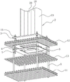
Fig. 1 is a schematic view of the overall structure of embodiment 1 of the present application.
Fig. 2 is a schematic structural view showing a steel bar of a facing layer in embodiment 1 of the present application.
Fig. 3 is a schematic view of the overall structure of embodiment 2 of the present application.
Fig. 4 is a schematic structural diagram of the casting hole in embodiment 2 of the present application.
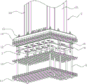
Fig. 5 is a schematic view of the overall structure of embodiment 3 of the present application.
Fig. 6 is a schematic structural view illustrating a positioning plate according to embodiment 3 of the present application.
Description of reference numerals: 1. pouring a concrete layer in situ; 2. a steel column; 3. a column base plate; 4. an anchor bolt hole; 5. an anchor bolt bracket; 6. an anchor bolt; 7. positioning a plate; 8. positioning holes; 9. pouring holes; 10. a rib plate; 11. a bottom plate steel bar; 12. surface layer reinforcing steel bars; 13. a temperature rib; 14. reinforcing the concrete layer; 15. a nut; 16. a cross-shaped column; 17. a first end plate; 18. a connecting plate; 19. a second end plate; 20. a side plate; 21. steel plate walls; 22. a third end plate.
Detailed Description
The present application is described in further detail below with reference to figures 1-6.
The embodiment of the application discloses conversion layer steel column mounting structure.
Example 1:
referring to fig. 1 and 2, a conversion layer steel column mounting structure includes cast-in-place concrete layer 1, steel column 2 and anchor bolt support 5 buried underground in cast-in-place concrete layer 1, fixedly connected with anchor bolt 6 on anchor bolt support 5, the tip of anchor bolt 6 stretches out from cast-in-place concrete layer 1 and is connected with steel column 2.
The position of the cast-in-place concrete layer 1 close to the bottom of the cast-in-place concrete layer is pre-embedded with a plurality of bottom plate reinforcing steel bars 11 which are arranged vertically and horizontally, the middle position of the cast-in-place concrete layer 1 is pre-embedded with a plurality of temperature bars 13 which are arranged vertically and horizontally, and the position of the cast-in-place concrete layer 1 close to the top of the cast-in-place concrete layer is pre-embedded with a plurality of surface layer reinforcing steel bars 12 which are arranged vertically and horizontally.
Bottom plate reinforcing bar 11 and temperature muscle 13 all with crab-bolt support 5 welded connection, have improved the stability that crab-bolt support 5 and cast-in-place concrete layer 1 are connected to the stability of steel column 2 has been improved. The bottom plate reinforcing steel bars 11, the temperature ribs 13 and the surface layer reinforcing steel bars 12 act on the cast-in-place concrete layer 1 together, and the pulling resistance, the crack resistance and the shearing resistance of the cast-in-place concrete layer 1 are improved.
A plurality of positioning plates 7 are welded on the anchor bolt bracket 5, preferably, the number of the positioning plates 7 is 2, and the positioning plates are arranged along the vertical direction. A plurality of positioning holes 8 are formed in the positioning plates 7, preferably, the number of the positioning holes 8 is set to be 4, corresponding anchor bolt holes 4 in the two positioning plates 7 are coaxially arranged, and anchor bolts 6 penetrate through the anchor bolt holes 4 and are fixed on the two positioning plates 7 in a welding mode. Still seted up on locating plate 7 and pour hole 9, pour hole 9 and realized the concrete connection of locating plate 7 both sides, improved cast in situ concrete layer 1's bulk strength.
Utilize crab-bolt support 5 and locating plate 7 to carry out fixed mounting to crab-bolt 6, improved the joint strength of crab-bolt 6 with the concrete support seat, reduced the risk that crab-bolt 6 extracted from the concrete support seat, locating plate 7 carries on spacingly to crab-bolt 6, reduces the risk that 6 emergence displacements of in-process crab-bolt of pouring, makes things convenient for follow-up crab-bolt 6 and steel column 2's cooperation installation.
The steel column 2 comprises a cross column 16 with a cross-shaped horizontal section and first end plates 17 vertically welded to four end portions of the cross column 16 along the length direction of the cross column 16, a rectangular column bottom plate 3 is welded and fixed to the bottom of the steel column 2, and the bottom of the cross column 16 and the bottom of the first end plates 17 are all fixedly connected with the column bottom plate 3 in a welding mode. The cross section of the steel column 2 is set to be cross-shaped, and the end part of the cross column 16 is provided with the first end plate 17, so that the steel column 2 has strong bending resistance, and the overall strength of the steel column 2 is improved.
A plurality of anchor bolt holes 4 are formed in the column bottom plate 3, the anchor bolt holes 4 correspond to the positioning holes 8, and anchor bolts 6 penetrate through the anchor bolt holes 4 and are fixedly connected with the column bottom plate 3 through bolts. The tip threaded connection that crab-bolt 6 stretches out concrete layer has a plurality of nuts 15, and is preferred, and the quantity of nut 15 sets up to 3, and a nut 15 is located the 3 below of column bottom plate for fix a position column bottom plate 3, and two 15 combined action of nut compress tightly column bottom plate 3 on concrete layer's top terminal surface, and the centre gripping has the gasket between nut 15 and the column bottom plate 3, and the gasket has improved the bolt and to column bottom plate 3's active area, improves the stability of connecting. Double nut 15 has reduced nut 15 and has produced not hard up risk, guarantees that nut 15 compresses tightly steel column 2 and fixes at crab-bolt 6.
The secondary grout has reinforced concrete layer 14 between cast-in-place concrete layer 1 and the column bottom plate 3, and reinforced concrete layer 14 uses the high strength grout material to pour the shaping, and concrete layer has higher intensity, reduces because of steel column 2 is too big to cast-in-place concrete layer 1 effort, the cast-in-place concrete layer 1 damaged risk that leads to.
The implementation principle of the embodiment 1 is as follows: when carrying out the installation of steel column 2, erect bottom plate reinforcing bar 11, temperature muscle 13 and surface course reinforcing bar 12 in corresponding position, then with crab-bolt support 5 respectively rather than welded fastening, then pour, it is spacing to pour in-process locating plate 7 to crab-bolt 6, prevent that crab-bolt 6 from taking place the displacement, pass crab-bolt hole 4 with crab-bolt 6, and use the bolt to compress tightly steel column 2 and fix on the support column, then use the high strength grout material to carry out the secondary and pour, it can to wait to strengthen concrete layer 14 and solidify. Utilize crab-bolt support 5 to carry out fixed connection to crab-bolt 6, utilize crab-bolt 6 to the fixed connection of column bottom plate 3, realized having improved steel column 2 and cast-in-place concrete layer 1's joint strength, improved steel column 2 and cast-in-place unstable problem of being connected of building concrete layer 1.
Example 2:
referring to fig. 3 and 4, the embodiment of the present application differs from embodiment 1 in that the horizontal cross-sectional shape of the steel column 2 is H-shaped, the steel column 2 includes a connecting plate 18, second end plates 19 integrally formed at both ends of the connecting plate 18, and side plates 20 welded to the side walls of the connecting plate 18, the number of the side plates 20 is two and parallel to the second end plates 19, and the connecting plate 18, the second end plates 19, and the side plates 20 are all welded to the column bottom plate.
The implementation principle of the embodiment 2 is as follows: set up the cross sectional shape of steel column 2 into H shape to set up curb plate 20 at the lateral wall of connecting plate 18, steel column 2 and the second end plate 19 combined action of shaping on steel column 2 have improved the anti bending capability of steel column 2, make the difficult emergence of steel column 2 warp, have higher intensity.
Example 3:
referring to fig. 5 and 6, the embodiment of the present application is different from embodiment 1 in that the steel column 2 includes a steel plate wall 21 having an L-shaped horizontal section, a plurality of third end plates 22 welded to an end portion and a side wall of the steel plate wall 21, and a plurality of ribs 10 welded and fixed between the steel plate wall 21 and the column bottom plate 3. The steel plate wall 21 is formed by welding a plurality of steel plates, and the steel plate wall 21, the third end plate 22 and the rib plate 10 are all connected with the column bottom plate 3 in a welding way. The column bottom plate 3 and the positioning plate 7 are both L-shaped, the number of anchor bolt holes 4 formed in the column bottom plate 3 and the number of positioning holes 8 formed in the positioning plate 7 are set to be 6, the number of pouring holes 9 formed in the positioning plate 7 is set to be 4, and the shape of the positioning plate is rectangular.
The implementation principle of the embodiment 3 is as follows: set up the shape of steel column 2 into L shape to set up the shape of column bottom plate 3 and locating plate 7 into L shape, make steel sheet wall steel column 2 have more connection crab-bolts 6, it builds concrete layer 1 with cast-in-place promptly has higher joint strength, makes steel column 2 difficult with cast-in-place 1 emergence of building concrete layer break away from, guarantees the stability that steel column 2 connects. And this steel sheet wall 21 steel column 2 can be used to the corner, saves the space of conversion layer more, improves space utilization.
The above embodiments are preferred embodiments of the present application, and the protection scope of the present application is not limited by the above embodiments, so: all equivalent changes made according to the structure, shape and principle of the present application shall be covered by the protection scope of the present application.
Claims (9)
1. The utility model provides a conversion layer steel column mounting structure, includes cast in situ concrete layer (1) and steel column (2), its characterized in that: the bottom fixedly connected with column bottom plate (3) of steel column (2), anchor bolt hole (4) have been seted up on column bottom plate (3), anchor bolt support (5) have been buried underground in cast-in-place concrete layer (1), fixedly connected with anchor bolt (6) on anchor bolt support (5), the tip of anchor bolt (6) stretches out cast-in-place concrete layer (1), anchor bolt (6) pass anchor bolt hole (4) and column bottom plate (3) fixed connection.
2. The installation structure for the steel columns of the conversion layer according to claim 1, wherein: fixedly connected with locating plate (7) on crab-bolt support (5), locating hole (8) have been seted up on locating plate (7), locating hole (8) with anchor bolt hole (4) correspond the setting, crab-bolt (6) pass locating hole (8) and anchor bolt hole (4) in proper order to with locating plate (7) and column bottom plate (3) fixed connection.
3. The steel column mounting structure for the conversion layer as claimed in claim 2, wherein: and a pouring hole (9) is also formed in the positioning plate (7) in a penetrating manner.
4. The steel column mounting structure for the conversion layer as claimed in claim 2, wherein: the quantity of locating plate (7) sets up to a plurality ofly, and along vertical direction with crab-bolt support (5) fixed connection.
5. The installation structure for the steel columns of the conversion layer according to claim 1, wherein: and a rib plate (10) is fixedly connected at the joint of the steel column (2) and the column bottom plate (3).
6. The installation structure for the steel columns of the conversion layer according to claim 1, wherein: bottom plate reinforcing bars (11) are buried in the cast-in-place concrete layer (1), and the anchor bolt support (5) is fixedly connected with the bottom plate reinforcing bars (11).
7. The installation structure for the steel columns of the conversion layer according to claim 1, wherein: surface layer reinforcing steel bars (12) are buried in the cast-in-place concrete layer (1), and the anchor bolts (6) are fixedly connected with the surface layer reinforcing steel bars (12).
8. The installation structure for the steel columns of the conversion layer according to claim 1, wherein: temperature muscle (13) are buried underground in cast-in-place concrete layer (1), crab-bolt support (5) with temperature muscle (13) fixed connection.
9. The installation structure for the steel columns of the conversion layer according to claim 1, wherein: and a reinforced concrete layer (14) is secondarily grouted between the cast-in-place concrete layer (1) and the column bottom plate (3), and the reinforced concrete layer (14) is poured by adopting high-strength grouting material.
Priority Applications (1)
| Application Number | Priority Date | Filing Date | Title |
|---|---|---|---|
| CN202121991071.4U CN216109354U (en) | 2021-08-23 | 2021-08-23 | Conversion layer steel column mounting structure |
Applications Claiming Priority (1)
| Application Number | Priority Date | Filing Date | Title |
|---|---|---|---|
| CN202121991071.4U CN216109354U (en) | 2021-08-23 | 2021-08-23 | Conversion layer steel column mounting structure |
Publications (1)
| Publication Number | Publication Date |
|---|---|
| CN216109354U true CN216109354U (en) | 2022-03-22 |
Family
ID=80727925
Family Applications (1)
| Application Number | Title | Priority Date | Filing Date |
|---|---|---|---|
| CN202121991071.4U Active CN216109354U (en) | 2021-08-23 | 2021-08-23 | Conversion layer steel column mounting structure |
Country Status (1)
| Country | Link |
|---|---|
| CN (1) | CN216109354U (en) |
Cited By (1)
| Publication number | Priority date | Publication date | Assignee | Title |
|---|---|---|---|---|
| CN115434513A (en) * | 2022-09-29 | 2022-12-06 | 上海宝冶冶金工程有限公司 | Construction method for embedding anchor bolt |
-
2021
- 2021-08-23 CN CN202121991071.4U patent/CN216109354U/en active Active
Cited By (2)
| Publication number | Priority date | Publication date | Assignee | Title |
|---|---|---|---|---|
| CN115434513A (en) * | 2022-09-29 | 2022-12-06 | 上海宝冶冶金工程有限公司 | Construction method for embedding anchor bolt |
| CN115434513B (en) * | 2022-09-29 | 2023-11-21 | 上海宝冶冶金工程有限公司 | Construction method for embedding anchor bolts |
Similar Documents
| Publication | Publication Date | Title |
|---|---|---|
| CN103924505B (en) | Use prefabricated steel-concrete combination T beam and the construction method of Wavelike steel webplate | |
| CN216109354U (en) | Conversion layer steel column mounting structure | |
| CN111188457A (en) | Edge sealing beam structure of super high-rise steel structure building and construction method | |
| CN113202185B (en) | Energy-saving building steel structure system and installation process thereof | |
| CN207812307U (en) | The construction system of Cable stayed Bridge Main Tower and steel anchor beam | |
| CN106498973A (en) | A kind of assembled type base for power transmission line iron tower and its installation method | |
| CN206829461U (en) | After pour teeth groove and be linked and packed formula precast slab | |
| CN213268587U (en) | Concrete column's antidetonation strengthening mechanism | |
| CN209873809U (en) | Foundation pit limb platform system | |
| CN110185182A (en) | Concrete folding plate construction is with being stably connected with structure and construction method | |
| CN202610695U (en) | Corrugated steel web type pre-tensioned prestressed concrete I-type beam | |
| CN206554385U (en) | Combining structure for assembled architecture | |
| CN215165648U (en) | Vertical bearing device of reverse construction area structure that can retrieve | |
| CN213203667U (en) | Supporting structure for post-cast strip-striding temporary lane of top plate of ground depot | |
| CN212026598U (en) | Structure system suitable for assembled steel structure building | |
| CN212026317U (en) | Connection structure based on piled raft foundation sets up tower crane foundation | |
| CN211874127U (en) | Prefabricated enclosure and mounting structure thereof | |
| CN211735010U (en) | Assembled earthing corrugated steel plate-prestressed concrete combination arched bridge | |
| CN113417459A (en) | Cantilever structure formwork support system and construction method | |
| CN112227580A (en) | Steel pipe truss prestressed hollow superimposed sheet | |
| CN113279423A (en) | Prefabricated column pier and post-cast strip foundation beam assembly integral construction method | |
| CN215858253U (en) | Concrete floor stand node connection structure | |
| CN217758906U (en) | Assembled anti-settlement beam slab foundation structure | |
| CN217630795U (en) | Connecting structure of prefabricated plate and structural beam | |
| CN216157151U (en) | Structure template support system encorbelments |
Legal Events
| Date | Code | Title | Description |
|---|---|---|---|
| GR01 | Patent grant | ||
| GR01 | Patent grant |