Flexible balance machine for electronic components
Technical Field
The utility model relates to a 3C electronic components equipment technique specifically is a flexible balance machine of electronic components.
Background
The chip and the 3C electronic component are various in types, various in types and large in size range difference of 0.8-16 mm, and the products need to be subjected to electrical performance test before being mounted by a chip mounter, and are in a bulk material state after the test is finished. According to investigation, the bulk cargo that the test was accomplished needs the manual work to put into the corresponding charging tray, carries out next process. Artifical balance is adopted in traditional 3C trade, and its defect lies in: the electronic components are small, the front and back of partial components are not obvious, the precision requirement is high, the manual speed is low, the efficiency is low, and the requirement for large-batch production cannot be met. In recent years, automatic tray placing machines have appeared along with the development of technology, but the compatibility is poor, only a few kinds of electronic components can be placed, and although vision and robots are combined, most of vision is arranged at a discharge port and used for detecting the defects of the assembled components.
SUMMERY OF THE UTILITY MODEL
The utility model overcomes prior art's is not enough, provides a flexible balance machine of electronic components. The problem of traditional balance material singleness, the flexibility is poor, the uniformity is poor, balance inefficiency scheduling shortcoming is solved.
In order to achieve the above purpose, the present invention is achieved by the following technical solutions.
A flexible electronic component tray placing machine comprises a working platform and a control system, wherein a robot is fixed on the working platform, and the control system controls the tray placing action of the robot; the robot is provided with a suction nozzle, and a conveying line, a carrying disc and a material distributing device are fixed on the working platform; the device comprises a carrying disc, a first visual capture device and a second visual capture device, wherein the first visual capture device is arranged above the carrying disc and used for capturing the image of the placing position of the electronic component on the carrying disc; the second visual capture device is arranged on one side of the suction nozzle and is used for capturing an image of the action of the suction nozzle; the first visual capture device and the second visual capture device are respectively in signal connection with the control system.
Furthermore, the material distribution device comprises a vibration feeding device and a flat vibration material distribution device, the vibration feeding device comprises a straight vibration device, the upper end of the straight vibration device is fixedly connected with a support frame, and the upper end of the support frame is fixedly connected with a material loading disc; the flat vibration material distributing device comprises a flat vibration device and a material distributing disc arranged on the flat vibration device, and a material outlet of the material feeding disc is arranged above the material distributing disc.
Furthermore, a light source is arranged at the bottom of the distributing disc.
Further, the first visual capture device and the second visual capture device are respectively provided with a light source.
Further, the light source of the first visual capture device is a three-color lamp.
Furthermore, the periphery of the carrying disc is provided with a flange.
Further, the first and second visual capture devices are industrial cameras.
The utility model discloses produced beneficial effect does for prior art.
The utility model captures the placing action of the robot from the upper part of the carrying disc and the side part of the suction nozzle by adding and changing the position of the vision device and matching with the light source, provides more accurate image support, and further adjusts the action of the robot in time through the control system to improve the refinement of the action; secondly, a material distributing device is combined to separate the feeding and the distributing, the feeding is carried out through vibration of a direct vibrator, then vibration of a flat vibrator is carried out to disperse parts, the parts are matched with a robot to clamp, a large number of materials can be loaded into a feeding tray at one time, and meanwhile, the device can be suitable for grabbing of various materials by combining a vision device, so that the flexibility of the device is increased, and the device is suitable for various materials; the addition of the visual fine positioning mechanism solves the defect that the existing material placing machine is inaccurate in placement.
Drawings
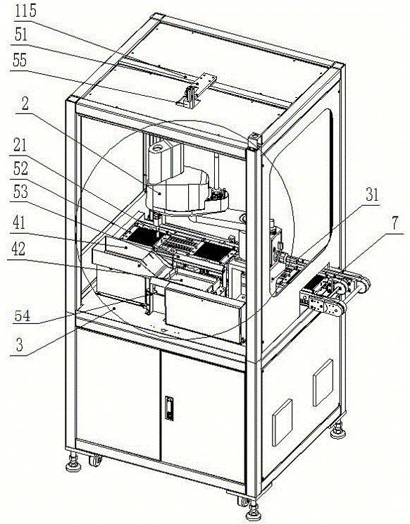
FIG. 1 is a schematic diagram of an external structure of a wobble plate machine according to an embodiment.
FIG. 2 is a schematic diagram of an internal structure of the wobble plate machine according to the embodiment.
Fig. 3 is a partially enlarged view of fig. 2.
Fig. 4 is a schematic structural diagram of the conveying line of the plate arranging machine according to the embodiment.
Fig. 5 is a schematic structural diagram of the material separating device according to the embodiment.
FIG. 6 is a schematic view of the connection between the load plate and the jacking device in the embodiment.
In the figure:
the display device comprises a shell 1, an upper shell 11, a lower shell 12, a display 111, an operation area 112, a door opening handle 113, a viewing window 114, a beam 115, a three-color lamp 116, a foot cup 121 and a caster 122.
The device comprises a robot 2, a vacuum suction nozzle 21, a working platform 3, a robot connecting plate 31, a threading device 33, a vibration feeding device 41, a flat vibration material separating device 42, a straight vibration device 411, a supporting frame 412, a material feeding tray 413, a flat vibration device 421 and a material separating tray 422.
Reference numeral 51 denotes a camera connecting plate, 52 denotes a bar light source, 53 denotes a second industrial camera module, 54 denotes a light source fixing plate, and 55 denotes a first industrial camera module.
7 is a conveying line, 71 is a stop cylinder, 72 is a conveying line guide strip, 75 is a blanking position stop strip, 76 is a positioning stop cylinder, 77 is a conveying line connecting plate, 78 is a positioning stop edge, 8 is a loading disc, 91 is a cylinder, 92 is a guide column, and 93 is a jacking plate.
Detailed Description
In order to make the technical problem, technical scheme and beneficial effect that the utility model will solve more clearly understand, combine embodiment and attached drawing, it is right to go on further detailed description the utility model discloses. It should be understood that the specific embodiments described herein are merely illustrative of the invention and are not intended to limit the invention. The technical solution of the present invention is described in detail below with reference to the embodiments and the drawings, but the scope of protection is not limited thereto.
As shown in fig. 1-4, the flexible tray arranging machine for electronic components includes a casing 1, where the casing 1 includes an upper casing 11 and a lower casing 12, the upper casing 11 is located at the top end of the lower casing 12, four corners of the bottom end of the lower casing 12 are respectively provided with a foot cup 121 and a caster 122, and the foot cup 121 and the caster 122 are connected in a bolt-nut connection manner; the front panel of casing 1 is fixed with display 111 through the buckle, there is operating area 112 display 111 below, there are door opening handle 113 and observation window 114 left front side of casing 1, casing 1 right side is equipped with feed opening 10, it fixes the outside at work platform 3 to go up casing 11 and lower casing 12, four-axis robot 2 is fixed through robot connecting plate 31 in work platform 3's top, there is vacuum suction nozzle 21 robot 2 end, it is fixed with first industry camera subassembly 55 through camera connecting plate 51 on the crossbeam 115 of last casing 11, first industry camera subassembly 55 is located the top position of year dish 8, be used for shooing the locating position image of electronic components on year dish 8, the top bolt fastening tristimulus lamp 116 of last casing 11, tristimulus lamp 116 and the cooperation of first industry camera subassembly 55 snatch the visual image.
The working platform 3 is provided with the carrying disc 8, the carrying disc 8 is accurately positioned through the flanges 78 on two sides, as shown in fig. 6, the carrying disc 8 is positioned through a pin control and a jacking plate 93, the jacking plate 93 is connected with a guide column 92 through a bolt, and the air cylinder 91 is connected with the working platform 3 through a bolt. The working platform 3 is further connected with a bar-shaped light source 52 through a light source fixing plate 54, one side of the bar-shaped light source 52 is provided with a second industrial camera component 53, the second industrial camera component 53 is connected with the working platform 3 through a bolt, the second industrial camera component 53 is arranged on one side of the vacuum suction nozzle 21, and the second industrial camera component 53 and the bar-shaped light source 52 are matched for capturing images of the action of the vacuum suction nozzle 21.
A material distribution device is arranged on one side of the carrier tray 8, the material distribution device comprises a vibration loading device 41 and a flat vibration material distribution device 42, as shown in fig. 5, the vibration loading device 41 comprises a straight vibrator 411, the upper end of the straight vibrator 411 is fixedly connected with a support frame 412, and the upper end of the support frame 412 is fixedly connected with a material loading tray 413; the flat vibration material distributing device 42 comprises a flat vibrator 421 and a material distributing disc 422 arranged thereon, the material outlet of the upper material disc 413 is arranged above the material distributing disc 422, and the bottom of the material distributing disc 422 is provided with a light source.
The transfer chain 7 is connected with work platform 3 through transfer chain connecting plate 77, and threader 33 is connected with work platform 3 through the bolt, and transfer chain gib block 72 passes through the bolt fastening on transfer chain 7, keeps off and stops cylinder 71 and pass through the bolt fastening of side on transfer chain 7, and the location keeps off and stops cylinder 76 and location flange 78 and pass through the bolt fastening on transfer chain 7, and unloading position blend stop 75 passes through the bolt fastening at transfer chain 7. The material of the blanking position barrier strip 75 is resin.
The flexible tray placing machine of the embodiment captures the placing action of the robot 2 from the upper part of the carrying tray 8 and the side part of the vacuum suction nozzle 21 by adding and changing the position of the visual device and matching with the light source, provides more accurate image support, provides data to the control system, and further performs fine adjustment and lifting action on the action of the robot through the control system; wherein the control system adopts a control system of the existing balance machine; secondly, a material distributing device is combined to separate the feeding and the distributing, the feeding is carried out through vibration of a direct vibrator, then vibration of a flat vibrator is carried out to disperse parts, the parts are matched with a robot to clamp, a large number of materials can be loaded into a feeding tray at one time, and meanwhile, the device can be suitable for grabbing of various materials by combining a vision device, so that the flexibility of the device is increased, and the device is suitable for various materials; the addition of the visual fine positioning mechanism solves the defect that the existing material placing machine is inaccurate in placement.
The above description is for further details of the present invention with reference to specific preferred embodiments, and it should not be understood that the embodiments of the present invention are limited thereto, and it will be apparent to those skilled in the art that the present invention can be implemented in a plurality of simple deductions or substitutions without departing from the scope of the present invention, and all such alterations and substitutions should be considered as belonging to the present invention, which is defined by the appended claims.