CN213462931U - Plant root topdressing device for agriculture based on solid fertilizer - Google Patents
Plant root topdressing device for agriculture based on solid fertilizer Download PDFInfo
- Publication number
- CN213462931U CN213462931U CN202021715469.0U CN202021715469U CN213462931U CN 213462931 U CN213462931 U CN 213462931U CN 202021715469 U CN202021715469 U CN 202021715469U CN 213462931 U CN213462931 U CN 213462931U
- Authority
- CN
- China
- Prior art keywords
- fertilizer
- box
- slide
- hole
- plate
- Prior art date
- Legal status (The legal status is an assumption and is not a legal conclusion. Google has not performed a legal analysis and makes no representation as to the accuracy of the status listed.)
- Active
Links
Images


Abstract
The utility model discloses a plant roots topdressing device is used to agricultural based on solid fertilizer, the power distribution box comprises a box body, the top of box is provided with fly leaf one. This plant root device that topdresses for agricultural based on solid fertilizer, through the box, dig the hole structure, the fertilization structure, fly leaf two, servo motor one, the feed cylinder, the standpipe, the can fertilizer, the rotation axis, spiral feeding blade, electric telescopic handle two, the diaphragm, servo motor two, the frame, installation axle and helical blade's cooperation is used, adopt earlier to dig the hole structure and carry out the excavation in fertilization hole, after the excavation is accomplished, promote the box and remove, make fertilization structure discharge end be located fertilization hole directly over and to the inside fertilizer that adds in of fertilization hole, meanwhile, dig the hole structure and carry out the excavation in another fertilization hole, mechanized hole and fertilization operation have been adopted, semi-automatization's topdressing operation has been realized, the part of manual work has been reduced, the effectual work load that has reduced the topdressing, time saving and labor saving.
Description
Technical Field
The utility model relates to an agricultural fertilizer field specifically is a plant roots topdressing device for agricultural based on solid fertilizer.
Background
The fertilizer is a substance which provides one or more nutrient elements necessary for plants, improves the soil property and improves the soil fertility level, and is one of the material bases of agricultural production. Mainly comprises ammonium phosphate fertilizer, macroelement water-soluble fertilizer, secondary element fertilizer, biological fertilizer, organic fertilizer, multi-dimensional field energy concentrated organic fertilizer and the like. Solid and fluid fertilizers can be classified according to the physical state of the fertilizer. Solid fertilizers are further classified into powdery and granular fertilizers. The fluid fertilizer is a fertilizer in a liquid state at normal temperature and normal pressure.
This application improves to prior art, when carrying out the root additional fertilizer among the prior art, often adopts the manual work to excavate the fertilization hole, then manual inside of scattering the fertilization hole with solid fertilizer, and because the planting area is wide, the work load of digging pit and fertilization is big, and it is inefficient to the additional fertilizer of plant, wastes time and energy.
SUMMERY OF THE UTILITY MODEL
An object of the utility model is to provide a plant roots topdressing device for agricultural based on solid fertilizer to solve the problem that proposes in the above-mentioned background art.
In order to achieve the above object, the utility model provides a following technical scheme:
a plant root topdressing device for agriculture based on solid fertilizer comprises a box body, wherein a first movable plate is arranged at the top of the box body, a hole digging structure is fixedly arranged at the top of the first movable plate, a fertilizer applying structure is arranged at the top of the first movable plate, the hole digging structure comprises a transverse plate, a second electric telescopic rod is fixedly arranged on one side of the top of the transverse plate, a frame is fixedly connected with the driving end of the second electric telescopic rod, a second servo motor is fixedly arranged inside the frame, a mounting shaft is fixedly connected with the driving end of the second servo motor, helical blades are sleeved on the outer wall of the mounting shaft, the fertilizer applying structure comprises a second movable plate, a charging barrel is welded and arranged at the top of the second movable plate, a first servo motor is fixedly arranged on one side of the charging barrel, a rotating shaft is fixedly connected with the driving end of the, the top of fly leaf two is passed through landing leg fixedly connected with fertilizer can, one side fixed mounting of fertilizer can bottom has the standpipe.
As a further aspect of the present invention: the top of box runs through and has seted up two slides, fixed mounting has two slide bars between the both sides of box inner wall, rotate through the bearing between the both sides of box inner wall and install the threaded rod, two be provided with the driving plate between slide bar and the threaded rod, the top fixed mounting of driving plate has two welded plates, and the bottom fixed connection of slide and fly leaf one is passed through at the top of welded plate, the bottom fixed mounting of box inner wall has the drive structure, and the transmission is connected between drive structure and the threaded rod.
As a further aspect of the present invention: the top fixed mounting of box has three slide two, slide two sliding connection have rather than the slider of looks adaptation, and the top of slider and the bottom fixed connection of fly leaf one.
As a further aspect of the present invention: the driving structure consists of a servo motor and a chain wheel transmission structure, the chain wheel transmission structure consists of two chain wheels and a chain, and the two chain wheels are connected through chain transmission.
As a further aspect of the present invention: two slide holes and threaded holes are respectively arranged on one side of the transmission plate in an inserting mode, the transmission plate is in transmission connection with the threaded rod through the threaded holes, the threaded rod is matched with the threaded holes, the transmission plate is in sliding connection with the sliding rod through the slide holes, and the sliding rod is matched with the slide holes.
As a further aspect of the present invention: the top fixed mounting of fly leaf one has two slide one, slide one sliding connection has the sliding block rather than the looks adaptation, and the top of sliding block and the bottom fixed connection of fly leaf two, the top of fly leaf one just is located and digs fixed mounting between hole structure and the fertilization structure has two electric telescopic handle one, and electric telescopic handle one's drive end and fly leaf two fixed connection.
Compared with the prior art, the beneficial effects of the utility model are that:
1. the utility model uses the cooperation of the box body, the hole digging structure, the fertilizing structure, the movable plate II, the servo motor I, the charging barrel, the vertical pipe, the fertilizer box, the rotating shaft, the spiral feeding blade, the electric telescopic rod II, the transverse plate, the servo motor II, the frame, the mounting shaft and the spiral blade, firstly adopts the hole digging structure to dig the fertilizer pit, after the digging is completed, the box body is pushed to move, the discharging end of the fertilizing structure is positioned right above the fertilizer pit and fertilizer is added into the fertilizer pit, meanwhile, the hole digging structure excavates another fertilizer pit, adopts the mechanized hole digging and fertilizer applying operations, realizes the semi-automatic fertilizer applying operation, reduces the parts of manual work, effectively reduces the workload of fertilizer applying, saves time and labor, and when fertilizer is guided into the fertilizer applying pit, the hole digging structure also excavates a new fertilizer applying pit, is beneficial to the synchronous fertilizing and digging pit, the top dressing effect is high.
2. The utility model discloses an electric telescopic handle one, slide one, the sliding block, the welded plate, slide two, the slide bar, the driving plate, the threaded rod, the cooperation of drive structure and fly leaf one is used, the welded plate drives fly leaf one and carries out horizontal removal regulation, and then row's material position to digging the position of digging the hole structure and fertilizing structure adjusts in step, make the device can be applicable to different operational environment, and electric telescopic handle one flexible can further drive fertilizing structure and rotate, and then realize adjusting digging the interval between hole structure and the fertilizing structure, make the device be applicable to the plant topdressing of different planting intervals, the extensive applicability of device, high durability and convenient use.
Drawings
FIG. 1 is a schematic structural diagram of a solid fertilizer-based agricultural plant root topdressing device;
FIG. 2 is a schematic structural diagram of a fertilizing structure in a solid fertilizer-based agricultural plant root topdressing device;
FIG. 3 is a schematic structural diagram of a hole digging structure in an agricultural plant root topdressing device based on solid fertilizer;
FIG. 4 is a top view of a box body of the plant root topdressing device for agriculture based on solid fertilizer;
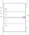
FIG. 5 is a top cross-sectional view of a housing of an agricultural plant root topdressing device based on solid fertilizer.
In the figure: the device comprises a box body 1, a first electric telescopic rod 2, a first sliding seat 3, a hole digging structure 4, a fertilizing structure 5, a sliding block 6, a second movable plate 7, a first servo motor 8, a charging barrel 9, a vertical pipe 10, a fertilizer box 11, a rotating shaft 12, a spiral feeding blade 13, a second electric telescopic rod 14, a transverse plate 15, a second servo motor 16, a frame 17, a mounting shaft 18, a spiral blade 19, a welding plate 20, a second sliding seat 21, a slide rail 22, a sliding rod 23, a transmission plate 24, a threaded rod 25, a driving structure 26 and a first movable plate 27.
Detailed Description
The technical solutions in the embodiments of the present invention will be described clearly and completely with reference to the accompanying drawings in the embodiments of the present invention, and it is obvious that the described embodiments are only some embodiments of the present invention, not all embodiments. Based on the embodiments in the present invention, all other embodiments obtained by a person skilled in the art without creative work belong to the protection scope of the present invention.
Referring to fig. 1 to 5, in an embodiment of the present invention, a solid fertilizer-based agricultural plant root topdressing device includes a box body 1 and a traveling wheel installed at the bottom of the box body 1, a first movable plate 27 is installed at the top of the box body 1, a hole digging structure 4 is fixedly installed at the top of the first movable plate 27, a fertilizer applying structure 5 is installed at the top of the first movable plate 27, the hole digging structure 4 includes a horizontal plate 15, a second electric telescopic rod 14 is fixedly installed at one side of the top of the horizontal plate 15, a driving end of the second electric telescopic rod 14 penetrates through the top of the horizontal plate 15 and extends to the lower side of the horizontal plate 15, a frame 17 is fixedly connected to a driving end of the second electric telescopic rod 14, a second servo motor 16 is fixedly installed inside the frame 17, a driving end of the second servo motor 16 penetrates through the inner wall of the frame 17 and extends to the, the outer wall of the mounting shaft 18 is sleeved with a helical blade 19, the fertilizing structure 5 comprises a second movable plate 7, the top of the second movable plate 7 is welded with a charging barrel 9, one side of the top of the charging barrel 9 is provided with a feed inlet in a penetrating manner, one side of the bottom of the charging barrel 9 is provided with a discharge pipe in a penetrating manner, one side of the charging barrel 9 is fixedly provided with a first servo motor 8, the driving end of the first servo motor 8 penetrates through one side of the charging barrel 9 and extends into the charging barrel 9, the driving end of the first servo motor 8 is fixedly connected with a rotating shaft 12, the outer part of the rotating shaft 12 is sleeved with a helical feeding blade 13, the top of the second movable plate 7 is fixedly connected with a fertilizer box 11 through a support leg, one side of the bottom of the fertilizer box 11 is fixedly provided with a vertical pipe 10, the bottom of the, two sliding rods 23 are fixedly installed between two sides of the inner wall of the box body 1, a threaded rod 25 is rotatably installed between two sides of the inner wall of the box body 1 through a bearing, a transmission plate 24 is arranged between the two sliding rods 23 and the threaded rod 25, two welding plates 20 are fixedly installed at the top of the transmission plate 24, the top of each welding plate 20 is fixedly connected with the bottom of the corresponding movable plate I27 through a slide rail 22, a driving structure 26 is fixedly installed at the bottom of the inner wall of the box body 1, the driving structure 26 is in transmission connection with the threaded rod 25, three sliding seats II 21 are fixedly installed at the top of the box body 1, the sliding seats II 21 are in sliding connection with sliding blocks matched with the sliding seats, the tops of the sliding blocks are fixedly connected with the bottoms of the corresponding movable plate I27, the driving structure 26 consists of a servo motor and a chain wheel transmission, two sliding holes and threaded holes are respectively penetrated and arranged on one side of the driving plate 24, the driving plate 24 is in transmission connection with the threaded rod 25 through the threaded holes, the threaded rod 25 is in adaptation with the threaded holes, the driving plate 24 is in sliding connection with the sliding rod 23 through the sliding holes, the sliding rod 23 is in adaptation with the sliding holes, two sliding seats I3 are fixedly mounted at the top of the movable plate I27, the sliding seats I3 are in sliding connection with the sliding blocks 6 in adaptation with the sliding seats, the top of the sliding blocks 6 is fixedly connected with the bottom of the movable plate II 7, the top of the movable plate I27 is fixedly mounted between the hole digging structure 4 and the fertilizing structure 5, two electric telescopic rods I2 are fixedly connected with the driving end of the electric telescopic rods I.
The utility model discloses a theory of operation is:
when the fertilizer hole digging machine is used, the servo motor II 16 drives the mounting shaft 18 to rotate and further drives the spiral blade 19 to rotate, meanwhile, the electric telescopic rod II 14 drives the frame 17 to descend, so that the digging operation of a fertilizer hole can be carried out, after the digging operation is finished, the electric telescopic rod II 14 resets, feed is stored in the fertilizer box 11 and enters the charging barrel 9 through the vertical pipe 10, the servo motor I8 drives the rotating shaft 12 to rotate and further drives the spiral feeding blade 13 to rotate, so that the direction of a fertilizer box discharging pipe in the charging barrel 9 can be transported and finally discharged into the fertilizer hole through the discharging pipe, the digging structure 4 is firstly adopted to dig the fertilizer, after the digging operation is finished, the box body 1 is pushed to move, the discharging end of the fertilizer structure 5 is positioned right above the fertilizer hole and fertilizer is added into the fertilizer hole, meanwhile, the hole digging structure 4 excavates another fertilizing pit, adopts mechanical hole digging and fertilizing operation, realizes semi-automatic fertilizing operation, reduces the part of manual work, effectively reduces the workload of fertilizing, saves time and labor, excavates a new fertilizing pit when fertilizer is introduced into the fertilizing pit, is beneficial to synchronous fertilization and digging, has high fertilizing effect, drives the threaded rod 25 to rotate by the driving structure 26, drives the movable plate 27 to transversely move and adjust by the welding plate 20 under the transverse transmission action of the threaded rod 25 and the transmission plate 24, further synchronously adjusts the digging position of the hole digging structure 4 and the discharging position of the fertilizing structure 5, enables the device to be suitable for different working environments, can further drive the fertilizing structure 5 to rotate by the extension of the electric telescopic rod one 2, and further realizes the adjustment of the distance between the hole digging structure 4 and the fertilizing structure 5, the device is suitable for plant topdressing at different planting intervals, and has wide applicability and convenient use.
Although the present invention has been described in detail with reference to the foregoing embodiments, it will be apparent to those skilled in the art that modifications may be made to the embodiments or portions thereof without departing from the spirit and scope of the invention.
Claims (6)
1. The utility model provides a plant roots topdressing device for agricultural based on solid fertilizer, includes box (1), its characterized in that: the top of the box body (1) is provided with a first movable plate (27), the top of the first movable plate (27) is fixedly provided with a hole digging structure (4), the top of the first movable plate (27) is provided with a fertilizing structure (5), the hole digging structure (4) comprises a transverse plate (15), one side of the top of the transverse plate (15) is fixedly provided with a second electric telescopic rod (14), the driving end of the second electric telescopic rod (14) is fixedly connected with a frame (17), the inside of the frame (17) is fixedly provided with a second servo motor (16), the driving end of the second servo motor (16) is fixedly connected with an installation shaft (18), the outer wall of the installation shaft (18) is sleeved with a helical blade (19), the fertilizing structure (5) comprises a second movable plate (7), the top of the second movable plate (7) is welded with a charging barrel (9), one side of the charging barrel (9) is fixedly provided, the drive end fixedly connected with rotation axis (12) of servo motor (8), spiral feeding blade (13) have been cup jointed to the outside of rotation axis (12), landing leg fixedly connected with fertilizer can (11) are passed through at the top of fly leaf two (7), one side fixed mounting of fertilizer can (11) bottom has standpipe (10).
2. The solid fertilizer-based agricultural plant root topdressing device according to claim 1, wherein: the top of box (1) runs through and has seted up two slide (22), fixed mounting has two slide bars (23) between the both sides of box (1) inner wall, rotate through the bearing between the both sides of box (1) inner wall and install threaded rod (25), two be provided with driving plate (24) between slide bar (23) and threaded rod (25), the top fixed mounting of driving plate (24) has two welded plates (20), and the bottom fixed connection of slide (22) and fly leaf (27) is passed through at the top of welded plate (20), the bottom fixed mounting of box (1) inner wall has drive structure (26), and the transmission is connected between drive structure (26) and threaded rod (25).
3. The solid fertilizer-based agricultural plant root topdressing device according to claim 2, characterized in that: the top fixed mounting of box (1) has three slide two (21), slide two (21) sliding connection have rather than the slider of looks adaptation, and the bottom fixed connection of the top of slider and fly leaf (27).
4. The solid fertilizer-based agricultural plant root topdressing device according to claim 2, characterized in that: the driving structure (26) is composed of a servo motor and a chain wheel transmission structure, the chain wheel transmission structure is composed of two chain wheels and a chain, and the two chain wheels are connected through chain transmission.
5. The solid fertilizer-based agricultural plant root topdressing device according to claim 2, characterized in that: two slide holes and threaded holes are respectively penetrated and arranged on one side of the transmission plate (24), the transmission plate (24) is in transmission connection with the threaded rod (25) through the threaded holes, the threaded rod (25) is matched with the threaded holes, the transmission plate (24) is in sliding connection with the sliding rod (23) through the slide holes, and the sliding rod (23) is matched with the slide holes.
6. The solid fertilizer-based agricultural plant root topdressing device according to claim 2, characterized in that: the top fixed mounting of fly leaf (27) has two slide (3), slide (3) sliding connection have rather than the sliding block (6) of looks adaptation, and the top of sliding block (6) and the bottom fixed connection of fly leaf two (7), the top of fly leaf (27) just is located and digs between hole structure (4) and fertilization structure (5) fixed mounting have two electric telescopic handle one (2), and the drive end and the fly leaf two (7) fixed connection of electric telescopic handle one (2).
Priority Applications (1)
| Application Number | Priority Date | Filing Date | Title |
|---|---|---|---|
| CN202021715469.0U CN213462931U (en) | 2020-08-18 | 2020-08-18 | Plant root topdressing device for agriculture based on solid fertilizer |
Applications Claiming Priority (1)
| Application Number | Priority Date | Filing Date | Title |
|---|---|---|---|
| CN202021715469.0U CN213462931U (en) | 2020-08-18 | 2020-08-18 | Plant root topdressing device for agriculture based on solid fertilizer |
Publications (1)
| Publication Number | Publication Date |
|---|---|
| CN213462931U true CN213462931U (en) | 2021-06-18 |
Family
ID=76362243
Family Applications (1)
| Application Number | Title | Priority Date | Filing Date |
|---|---|---|---|
| CN202021715469.0U Active CN213462931U (en) | 2020-08-18 | 2020-08-18 | Plant root topdressing device for agriculture based on solid fertilizer |
Country Status (1)
| Country | Link |
|---|---|
| CN (1) | CN213462931U (en) |
Cited By (1)
| Publication number | Priority date | Publication date | Assignee | Title |
|---|---|---|---|---|
| CN116171671A (en) * | 2023-04-27 | 2023-05-30 | 安徽农业大学 | Fertilizing device and method for oil tea planting |
-
2020
- 2020-08-18 CN CN202021715469.0U patent/CN213462931U/en active Active
Cited By (1)
| Publication number | Priority date | Publication date | Assignee | Title |
|---|---|---|---|---|
| CN116171671A (en) * | 2023-04-27 | 2023-05-30 | 安徽农业大学 | Fertilizing device and method for oil tea planting |
Similar Documents
| Publication | Publication Date | Title |
|---|---|---|
| CN103583128B (en) | Polynary fertilizer associating fertilizer distributor | |
| CN213462931U (en) | Plant root topdressing device for agriculture based on solid fertilizer | |
| CN209806406U (en) | Orchard fertilizer ditching and fertilizing machine | |
| CN211909584U (en) | Wheat field seeding assistor | |
| CN110637539A (en) | Fertilizing and ridging machine suitable for cassava ridge planting mode | |
| CN117178836A (en) | Seedling planting robot | |
| CN204616348U (en) | A kind of tumbrel | |
| CN108684252B (en) | Nest planing machine for selenium sand melon | |
| CN207075195U (en) | A kind of more ridge rotary tillage, ridging fertilization all-in-one machines with former | |
| CN112868491B (en) | Engineering processing apparatus suitable for municipal garden and flowers management and maintenance | |
| CN211378702U (en) | Fertilizing and ridging machine suitable for cassava ridge planting mode | |
| CN202222142U (en) | Portable machine integrating portable ditching, topdressing, suppressing and covering for wheat fields | |
| CN211982593U (en) | Quantity-controlled fertilizing device | |
| CN210247474U (en) | Furrow opener is planted in greenhouse | |
| CN206932597U (en) | One kind is T-shaped to swing to reduction box, four-wheel tractor orchard supervisor | |
| CN204579035U (en) | A kind of fertilising is across pond rotovator | |
| CN214507881U (en) | Multi-functional fertilizer injection unit for fruit tree cultivation | |
| CN110140461A (en) | It is a kind of to turn over device applied to organic Dry crop | |
| CN204948666U (en) | Fertilizer distributor is synthesized to grape | |
| CN214482165U (en) | Fruit seedling is planted and is used fertilizer injection unit | |
| CN220044115U (en) | Agricultural soil fertilizer fertilizies uses device that loosens soil | |
| CN212487142U (en) | Soil preparation fertilizer distributor special for macadamia nuts | |
| CN213485588U (en) | A fertilizer injection unit for farming | |
| CN220556879U (en) | Fertilization device for forestry planting | |
| CN211630802U (en) | Orchard farmyard manure fertilization high efficiency backfilling device |
Legal Events
| Date | Code | Title | Description |
|---|---|---|---|
| GR01 | Patent grant | ||
| GR01 | Patent grant |