CN213201524U - Stacking fixture and polar plate stack stacking production line - Google Patents
Stacking fixture and polar plate stack stacking production line Download PDFInfo
- Publication number
- CN213201524U CN213201524U CN202021104686.6U CN202021104686U CN213201524U CN 213201524 U CN213201524 U CN 213201524U CN 202021104686 U CN202021104686 U CN 202021104686U CN 213201524 U CN213201524 U CN 213201524U
- Authority
- CN
- China
- Prior art keywords
- conveying
- linear motion
- stacking
- plate
- manipulator
- Prior art date
- Legal status (The legal status is an assumption and is not a legal conclusion. Google has not performed a legal analysis and makes no representation as to the accuracy of the status listed.)
- Active
Links
Images


Abstract
The utility model relates to a pile up neatly anchor clamps and a polar plate buttress pile up neatly production line belongs to lead accumulator production technical field, the utility model provides a pair of pile up neatly anchor clamps, include: a base plate; the first manipulator is used for grabbing material stacking; the second manipulator is used for grabbing the partition plate; the first mechanical arm and the second mechanical arm are respectively connected to the bottom plate, and when the working end of the second mechanical arm is used for grabbing, the working end of the second mechanical arm is lower than the bottommost end of the working end of the first mechanical arm. Through install the second manipulator additional in the side of first manipulator, snatch the baffle of its next door at rethread second manipulator after the material is snatched to first manipulator, under the prerequisite of concentrating on same frock with multiple function demand, accomplished the task that different materials put things in good order, keep apart as required.
Description
Technical Field
The utility model belongs to the technical field of lead accumulator production, concretely relates to pile up neatly anchor clamps and a polar plate buttress pile up neatly production line.
Background
At present, the grid manufacturing process in the domestic storage battery industry gradually changes from a gravity casting mode to a continuous casting, continuous expansion, continuous net punching mode and the like.
With the improvement of labor cost in China and the promotion of industrial automation degree, the robot replaces manual stacking.
In the process of implementing the embodiments of the present invention, the inventor finds that at least the following defects exist in the background art:
when using the manipulator to deposit the material after the machine pile up neatly at present, exist:
1. materials in different batches cannot be physically isolated, so that the materials in different batches are easily mixed;
2. the functional integration level of the mechanical arm is low, and a plurality of groups of mechanical arms are needed to finish different grabbing tasks.
SUMMERY OF THE UTILITY MODEL
The utility model provides a stacking clamp and a polar plate stack stacking production line, aiming at solving the problems and solving the problems that 1, the physical isolation of different batches of materials can not be realized and the materials of different batches can be easily mixed when the materials are stored by using a manipulator after the stacking of a machine at present; 2. the functional integration level of the mechanical arm is low, and a plurality of groups of mechanical arms are needed to complete different grabbing tasks.
In order to achieve the above object, the utility model adopts the following technical scheme:
a pallet clamp comprising:
a base plate;
the first manipulator is used for grabbing material stacking;
the second manipulator is used for grabbing the partition plate;
the first mechanical arm and the second mechanical arm are connected to the lower end of the bottom plate respectively, and when the working end of the second mechanical arm is used for grabbing, the working end of the second mechanical arm is lower than the bottommost end of the working end of the first mechanical arm.
And a telescopic mechanism is arranged between the second mechanical arm and the bottom plate, and the second mechanical arm is connected to the bottom plate through the telescopic mechanism.
The second manipulator comprises a support rod and a vacuum chuck, and the vacuum chuck is fixed at the front end of the support rod.
The second manipulator is provided with a plurality of second manipulators which are evenly distributed around the first manipulator.
The first mechanical hand comprises an interval adjusting mechanism with two transmission ends and two stacking mechanical fingers, one stacking mechanical finger is arranged at one transmission end of the interval adjusting mechanism, the other stacking mechanical finger is arranged at the other transmission end of the interval adjusting mechanism, and the interval adjusting mechanism is in transmission connection with the stacking mechanical fingers.
A plate stack palletizing production line comprising:
a first feeding device;
a storage battery plate arranging device;
a second feeding device;
the stacking device comprises a stacking clamp and a mechanical arm, and the stacking clamp is connected to the end part of the mechanical arm;
the first feeding device is connected with a material receiving end of the storage battery pole plate arranging device, a discharge end of the storage battery pole plate arranging device is connected with a feed end of the second feeding device, and a discharge end of the second feeding device is connected with the stacking clamp of the stacking device.
The first feeding device comprises a conveyor belt, a first linear motion device, a second linear motion device, a third linear motion device and a mechanical claw, the transmission direction of the first linear motion device, the transmission direction of the second linear motion device and the transmission direction of the third linear motion device are perpendicular to each other, the second linear motion device is fixed at the output end of the first linear motion device, the third linear motion device is fixed at the output end of the second linear motion device, the mechanical claw is fixed at the output end of the third linear motion device, and the conveyor belt is arranged in the moving range of the mechanical claw.
The second feeding device comprises a rack, a conveying device and a caching device, the conveying device and the caching device are connected to the rack, the caching device comprises a lifting device and a plurality of bearing pieces, the bearing pieces are fixed at the working end of the lifting device, the bearing pieces are distributed on two sides of the conveying device, when the lifting device is lifted to the topmost position, the topmost surface of each bearing piece is higher than the conveying surface of the conveying device, and when the lifting device is lowered to the lowest position, the topmost surface of each bearing piece is lower than the conveying surface of the conveying device;
the bearing parts are cuboids, and the upper surfaces of the plurality of bearing parts are positioned on the same plane;
the conveying device comprises a first conveying belt and a second conveying belt, the first conveying belt and the second conveying belt are arranged adjacently, and the conveying surface of the first conveying belt is parallel to the conveying surface of the second conveying belt;
the buffer device further comprises an extension transmission rod, and the lifting device is fixedly arranged with the bearing piece through the extension transmission rod.
The storage battery pole plate arranging device is provided with two clamping baffle plates used for clamping and conveying storage battery pole plates, the second feeding device is provided with a conveying device and a rack, the conveying device is arranged on the rack, and the length of the topmost surface of the rack, which is far away from the conveying device, is at least greater than the thickness of the clamping baffle plates.
Still include the hydraulic lifting platform, press the lifting platform to be located the pile up neatly within range of pile up neatly device, the hydraulic lifting platform is including depositing platform, guardrail and elevating platform the guardrail is located deposit the platform outside, guardrail and hydraulic lifting platform fixed connection, the guardrail can be higher than the upper surface of depositing the platform or be less than the upper surface of depositing the platform through the lifting and drop of hydraulic lifting platform.
The beneficial effects of the utility model are that, through installing the second manipulator additional in the side of first manipulator, the baffle that its next door was snatched to rethread second manipulator after first manipulator snatchs the material can separate different batches of material for different batches of material differentiation comes.
Drawings
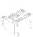
Fig. 1 is a schematic view of the overall structure of a plate stack stacking production line of the present invention;
fig. 2 is a schematic view of the overall structure of the first feeding device in the plate stack stacking production line of the present invention;
fig. 3 is a schematic diagram of the overall structure of a storage battery plate arranging device in a plate stack stacking production line of the utility model;
fig. 4 is a schematic view of the overall structure of a second feeding device in the plate stack stacking production line of the present invention;
fig. 5 is a schematic view of the overall structure of the stacking device in the plate stack stacking production line of the present invention;
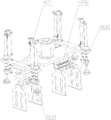
FIG. 6 is a schematic view of the overall structure of a stacking clamp according to the present invention;
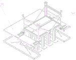
fig. 7 is the utility model relates to an overall structure schematic diagram of hydraulic elevating platform in polar plate buttress pile up neatly production line.
Labeled as: 1. a first feeding device; 101. a first linear motion device; 102. a second linear motion device; 103. a third linear motion device; 104. a gripper; 2. a storage battery plate arranging device; 201. a turning shaft; 202. turning over the rack of the finishing device; 203. a finishing device; 204. a leveling device; 3. a second feeding device; 301. a conveying device; 302. a cache device; 303. a frame; 304. a carrier; 4. a palletizing device; 401. a multi-joint robot; 402. a stacking clamp; 403. a base; 40201. a base plate; 40202. the distance adjusting mechanism, 40203 and the stacking manipulator; 40204. a vacuum chuck; 5. a hydraulic lifting platform.
Detailed Description
First, the battery plate collating device 2 is an issued patent of the present applicant at 20160928, and its application number is CN 201610858801.0.
The following will describe in detail a stacking fixture and a plate stack stacking production line scheme provided by embodiments of the present invention through several specific embodiments.
Example 1
Please refer to fig. 6, which shows an overall structure diagram of a pallet clamp according to the present invention, the pallet clamp includes:
a base plate 40201;
the first manipulator is used for grabbing material stacking;
the second manipulator is used for grabbing the partition plate;
the first manipulator and the second manipulator are connected to the lower end of a bottom plate 40201 respectively, and when the working end of the second manipulator is used for grabbing, the working end of the second manipulator is lower than the bottommost end of the working end of the first manipulator.
In the above embodiment, when the mechanical arm is used for stacking, the common mechanical arm can only stack the materials together when carrying the materials, and can not mechanically classify the materials in different batches, thereby easily causing the situation that the materials in different batches are mixed.
The utility model discloses pile up neatly anchor clamps are when using, at first manipulator snatchs the material, first manipulator snatchs the baffle on one side behind the material second manipulator snatchs, when pile up neatly anchor clamps place the material for the first time, at first the baffle is stably placed in target material department of depositing, later the second manipulator arranges the material in on the baffle, analogize in proper order, when snatching the material for the second time, the baffle that snatchs for the second time is stably placed on the material of placing for the first time, the material that snatchs for the second time is arranged in on the baffle that snatchs for the second time, further continuous above-mentioned.
This scheme improves the exposed core of arm on the basis of prior art arm, makes it not only have the arm and snatchs the function of material, also can snatch the baffle simultaneously and separate different batchs of material for different batchs of material can not mix, has ensured the quality of follow-up production product.
Example 2
Further, the utility model relates to a pile up neatly anchor clamps's another embodiment, telescopic machanism has between second manipulator and bottom plate 40201, the second manipulator passes through telescopic machanism connects on bottom plate 40201.
In the above embodiment, in order to ensure that the first manipulator does not touch other devices when grabbing materials, the second manipulator is additionally provided with the telescopic mechanism between the second manipulator and the bottom plate 40201, and when grabbing materials, the first manipulator retracts through the telescopic mechanism, so that the second manipulator is ensured not to touch other devices.
Example 3
Further, referring to fig. 6, in another embodiment of the stacking fixture of the present invention, the second manipulator includes a support rod and a vacuum chuck 40204, and the vacuum chuck 40204 is fixed at a front end of the support rod.
In the above embodiment, the bracing piece is used for prolonging vacuum chuck 40204 to the bottom of first manipulator, considers the face shape speciality of baffle, adopts vacuum chuck 40204 as the work end of second manipulator, relies on vacuum chuck 40204's single face adsorptivity, a slice baffle of absorption that can be accurate convenient to its simple structure, under the accurate circumstances of ensureing, still can guarantee the high efficiency.
Example 4
Further, referring to fig. 6, in another embodiment of the stacking jig of the present invention, the second manipulator has a plurality of manipulators, and the second manipulators are evenly distributed around the first manipulator.
In the above embodiment, one partition board is sucked by using a plurality of vacuum chucks 40204, so that stability in sucking the partition board can be ensured.
Example 5
Further, referring to fig. 6, according to another embodiment of the stacking clamp of the present invention, the first manipulator includes a spacing adjustment mechanism 40202 having two transmission ends and two stacking mechanical fingers 40203, one stacking mechanical finger 40203 is disposed at a transmission end of the spacing adjustment mechanism 40202, the other stacking mechanical finger 40203 is disposed at the other transmission end of the spacing adjustment mechanism 40202, and the spacing adjustment mechanism 40202 is in transmission connection with the stacking mechanical finger 40203.
In the above embodiment, the first manipulator grabs the material through the stacking mechanical fingers 40203, and the distance between the stacking mechanical fingers 40203 is adjusted by the distance adjusting mechanism 40202, so that the plurality of stacking mechanical fingers 40203 can clamp the material accurately. The existing manipulator cannot effectively adapt to materials of various sizes, and the equipment compatibility is low. This embodiment can accommodate materials of various sizes.
Furthermore, the first manipulator comprises two opposite L-shaped claw pieces and a distance adjusting mechanism 40202, and the output end of the distance adjusting mechanism 40202 is in transmission connection with the two opposite L-shaped claw pieces.
Example 6
Please refer to fig. 1, which shows an overall structure schematic diagram of a plate stack stacking production line of the present invention, the plate stack intelligent stacking production line includes:
a first feeding device 1;
a storage battery plate finishing device 2;
a second feeding device 3;
the stacking device 4 comprises a stacking clamp 402 and a mechanical arm, wherein the stacking clamp 402 is connected to the end part of the mechanical arm;
the first feeding device 1 is connected with a material receiving end of the storage battery pole plate arranging device 2, a discharging end of the storage battery pole plate arranging device 2 is connected with a feeding end of the second feeding device 3, and a discharging end of the second feeding device 3 is connected with the stacking clamp 402 of the stacking device 4.
In the embodiment, at present, the grid manufacturing process in the domestic storage battery industry is gradually changed from a gravity casting mode to a mode of continuous casting, continuous expansion, continuous net punching and the like of the grid. The grid produced by the gravity casting mode is required to be independently coated and surface dried to form a green plate, and then the green plate is manually collected, arranged and coiled to perform the next procedure, so that the mode has the advantages of higher repeated labor intensity, low production efficiency, high energy consumption and great pollution to the environment. The grid manufactured by the continuous mode can realize continuous coating, slitting, surface drying and stacking, and finally stacking and stacking are realized manually, the number of produced polar plates can reach about 750 plates/min, the requirement for manually collecting the polar plates is higher, the labor input is more, the labor intensity is higher, and the personnel input cost of a storage battery manufacturer is increased.
The production line in this embodiment can replace artifical pile up neatly, and in this production line, send the material to storage battery polar plate finishing device 2 through first material feeding unit 1 and go up to arrange in order, accomplish after the arrangement and transport the material pile up neatly device 4 one side through second material feeding unit 3, carry out the pile up neatly arrangement to the material through pile up neatly device to adopt the baffle to separate different batches of material.
The method has the advantages that 1, through intelligent and mechanical design, labor cost is saved and production efficiency is improved on a severely polluted operation site; 2. the structure is independent, the existing equipment is not required to be modified, and the universality and the compatibility are high; 3. the coordinate design is emphasized, so that the control is convenient; 4. the degree of automation is high, convenient operation, and the interaction is easy, and training cost is low. Due to the adoption of the mechanical arm, the stacking of the polar plate stack is more intelligent and flexible.
Further, the palletizing device 4 further comprises a multi-joint robot 401 and a base 403, the bottom of the multi-joint robot 401 is connected to the base 403, and a palletizing clamp 402 is arranged at the working end of the multi-joint robot 401. The articulated robot 401 is a mature product in the prior art, and research and development costs can be saved by adopting the articulated robot 401.
Example 7
Further, please refer to fig. 2, in another embodiment of the present invention, the first feeding device 1 includes a conveyor belt, a first linear motion device 101, a second linear motion device 102, a third linear motion device 103 and a gripper 104, a transmission direction of the first linear motion device 101, a transmission direction of the second linear motion device 102 and a transmission direction of the third linear motion device 103 are perpendicular to each other, the second linear motion device 102 is fixed at an output end of the first linear motion device 101, the third linear motion device 103 is fixed at an output end of the second linear motion device 102, the gripper 104 fixes an output end of the third linear motion device 103, and the conveyor belt is disposed in a moving range of the gripper 104.
In the above embodiment, the first linear motion device 101, the second linear motion device 102 and the third linear motion device 103 form a three-dimensional coordinate manipulator, which can accurately send materials to the storage battery plate arranging device 2, and the gripper 104 grips the materials on the conveyor belt within the moving range of the gripper to the storage battery plate arranging device 2.
The battery plate tidying device 2 has a turning shaft 201, a turning tidying device frame 202, a tidying device 203 and a beating device 204.
Example 8
Further, please refer to fig. 4, in another embodiment of the present invention, the second feeding device 3 includes a frame 303, a conveying device 301 and a buffering device 302, the conveying device 301 and the buffering device 302 are both connected to the frame 303, the buffering device 302 includes a lifting device and a plurality of bearing members 304, the plurality of bearing members 304 are fixed at a working end of the lifting device, the plurality of bearing members 304 are distributed at two sides of the conveying device 301, when the lifting device is lifted to a topmost position, a topmost surface of the plurality of bearing members 304 is higher than a conveying surface of the conveying device 301, and when the lifting device is lowered to a bottommost position, a topmost surface of the plurality of bearing members 304 is lower than a conveying surface of the conveying device 301.
In the above embodiment, the second feeding device 3 has a buffering function in addition to the conveying function, and the lifting device and the plurality of carriers are used for buffering the materials, wherein the lifting device is disposed at the lower end of the conveying surface of the conveying device 301, the carriers are disposed at two sides of the lower side of the conveying surface of the conveying device 301, the carriers can move up or down along with the lifting device, when the lifting device is lifted to the topmost position, the topmost surface of the plurality of carriers 304 is higher than the conveying surface of the conveying device 301, and when the lifting device is lowered to the lowest position, the topmost surface of the plurality of carriers 304 is lower than the conveying surface of the conveying device 301.
When the material storage device is used, if the upper end of the lifting device is provided with materials, the lifting device can ascend, and the bearing piece on the top of the lifting device can support the materials, so that the materials are temporarily stored at the upper end of the conveying device 301. The palletizing device 4 can also transfer the material grippers at this moment.
Further, referring to fig. 4, in another embodiment of the plate stack stacking production line of the present invention, the bearing members 304 are rectangular solids, and the upper surfaces of the plurality of bearing members 304 are located on the same plane;
the conveying device 301 comprises a first conveying belt and a second conveying belt, the first conveying belt and the second conveying belt are arranged adjacently, and the conveying surface of the first conveying belt is parallel to the conveying surface of the second conveying belt;
the buffer device 302 further comprises an extension transmission rod, by means of which the lifting device is fixedly arranged with the carrier 304.
In the above embodiment, the supporting members 304 are rectangular parallelepiped, and the upper surfaces of the supporting members 304 are located on the same plane, so that the top surfaces of the supporting members 304 are parallel, which is more stable when supporting the plate stack.
Conveying device 301 includes first conveyer belt and second conveyer belt, carries the plate pile through two thinner first conveyer belts and second conveyer belt, can guarantee the stability of plate pile, compares in single conveyer belt transmission, and the both sides of plate pile are lifted in first conveyer belt and second conveyer belt defeated, and its stability is strengthened, and if adopt single conveyer belt then this conveyer belt middle part when jacking, probably cause the plate pile to turn on one's side.
The buffer device 302 further includes an extension transmission rod for connecting the carrier 304 and the working end of the lifting device, and lifting the carrier 304 to a position close to the lower side of the first conveyor belt or the second conveyor belt, so that the working end of the lifting device does not easily collide with the first conveyor belt or the second conveyor belt when the working end of the lifting device is lifted.
Example 9
Further, please refer to fig. 3 and 4, the utility model relates to another embodiment of a polar plate pile up neatly production line, battery polar plate finishing device 2 has two and is used for the centre gripping to transport the tight baffle of clamp of battery polar plate, second material feeding unit 3 has conveyor 301 and frame 303, conveyor 301 establishes in frame 303, and the topmost length of the topmost face of frame 303 apart from conveyor 301 is greater than at least the tight baffle thickness of clamp.
In the above embodiment, when the storage battery plate arranging device 2 transfers the material, the clamping baffle plate may be close to the second feeding device 3, the clamping baffle plate may be parallel to the conveying surface of the second feeding device 3, and when the material contacts the conveying surface of the second feeding device 3, the material may be taken away by the second feeding device 3 for transportation, so as to ensure continuity of conveying the material between the storage battery plate arranging device 2 and the second feeding device 3, when the storage battery plate arranging device 2 transfers the material onto the second feeding device 3 by using the clamping baffle plate, the clamping baffle plate needs to be able to fall to a position below the conveying surface of the second feeding device 3, and the distance between the topmost surface of the rack 303 and the topmost surface of the conveying device 301 is at least greater than the thickness of the clamping baffle plate.
Example 10
Further, please refer to fig. 7, the utility model relates to a another embodiment of polar plate buttress pile up neatly production line still includes hydraulic elevating platform 5, presses elevating platform 5 to be located pile up neatly device 4's pile up neatly within range, and hydraulic elevating platform 5 is including depositing platform, guardrail and elevating platform 501 the guardrail is located deposit the platform outside, guardrail and hydraulic elevating platform 501 fixed connection, the guardrail can be higher than the upper surface of depositing the platform or be less than the upper surface of depositing the platform through hydraulic elevating platform 501's rising and falling.
Above-mentioned embodiment, when the buffer memory material, need set up the guardrail around depositing the platform to prevent that collapsing of material from causing the injury to personnel, nevertheless when pile up neatly device 4 puts things in good order the material on depositing the bench, the guardrail can influence pile up neatly device 4's normal pile up neatly, consequently sets up the guardrail as liftable guardrail and can solve the problem that the existence of depositing the outer guardrail of platform influences pile up neatly device 4.
It should be noted that all the directional indications (such as up, down, left, right, front, and rear … …) in the present embodiment are only used to explain the relative positional relationship between the components, the movement, and the like in a specific posture (as shown in the drawings), and if the specific posture is changed, the directional indication is changed accordingly.
In addition, descriptions related to "first", "second", and the like are used for descriptive purposes only and are not to be construed as indicating or implying relative importance or implicit to the number of technical features indicated. Thus, a feature defined as "first" or "second" may explicitly or implicitly include at least one such feature.
Technical solutions between various embodiments may be combined with each other, but must be realized by those skilled in the art, and when the technical solutions are contradictory or cannot be realized, such a combination should not be considered to exist, and is not within the protection scope of the present invention.
Claims (10)
1. A pallet clamp, comprising:
a base plate (40201);
the first manipulator is used for grabbing material stacking;
the second manipulator is used for grabbing the partition plate;
the first mechanical arm and the second mechanical arm are respectively connected to the lower end of a bottom plate (40201), and when the working end of the second mechanical arm performs grabbing operation, the working end of the second mechanical arm is lower than the bottommost end of the working end of the first mechanical arm.
2. The pallet clamp of claim 1, characterised in that a telescopic mechanism is provided between the second robot and the base plate (40201), and the second robot is connected to the base plate (40201) by the telescopic mechanism.
3. The pallet clamp of claim 2, wherein the second robot comprises a support bar and a vacuum chuck (40204), the vacuum chuck (40204) being fixed to a front end of the support bar.
4. The pallet clamp of claim 3, wherein the second robot is a plurality of robots, the second robot being evenly distributed around the first robot.
5. The pallet clamp of claim 1, wherein the first robot comprises a pitch adjustment mechanism (40202) having two transmission ends and two pallet mechanical fingers (40203), one of the pallet mechanical fingers (40203) being provided at one transmission end of the pitch adjustment mechanism (40202), the other of the pallet mechanical fingers (40203) being provided at the other transmission end of the pitch adjustment mechanism (40202), the pitch adjustment mechanism (40202) being in driving connection with the pallet mechanical fingers (40203).
6. The utility model provides a polar plate buttress pile up neatly production line which characterized in that includes:
a first feeding device (1);
a storage battery plate finishing device (2);
a second feeding device (3);
a palletizing device (4), the palletizing device (4) comprising a palletizing clamp as claimed in any one of claims 1 to 5 and a mechanical arm, the palletizing clamp being connected at an end of the mechanical arm;
the stacking device is characterized in that the first feeding device (1) is connected with a material receiving end of the storage battery plate arranging device (2), a discharge end of the storage battery plate arranging device (2) is connected with a feed end of the second feeding device (3), and a discharge end of the second feeding device (3) is connected with the stacking clamp of the stacking device (4).
7. The plate stack stacking production line according to claim 6, wherein the first feeding device (1) comprises a conveyor belt, a first linear motion device (101), a second linear motion device (102), a third linear motion device (103) and a mechanical claw (104), the transmission direction of the first linear motion device (101), the transmission direction of the second linear motion device (102) and the transmission direction of the third linear motion device (103) are perpendicular to each other, the second linear motion device (102) is fixed at the output end of the first linear motion device (101), the third linear motion device (103) is fixed at the output end of the second linear motion device (102), the mechanical claw (104) is fixed at the output end of the third linear motion device (103), and the conveyor belt is arranged in the moving range of the mechanical claw (104).
8. The plate pile palletizing production line according to claim 6, wherein the second feeding device (3) comprises a frame (303), a conveying device (301) and a buffering device (302), the conveying device (301) and the buffering device (302) are both connected to the frame (303), the buffering device (302) comprises a lifting device and a plurality of bearing pieces (304), the plurality of bearing pieces (304) are fixed at the working end of the lifting device, the plurality of bearing pieces (304) are distributed at two sides of the conveying device (301), when the lifting device is lifted to the topmost position, the topmost surface of the plurality of bearing pieces (304) is higher than the conveying surface of the conveying device (301), and when the lifting device is lowered to the lowest position, the topmost surface of the plurality of bearing pieces (304) is lower than the conveying surface of the conveying device (301);
the bearing parts (304) are cuboids, and the upper surfaces of the bearing parts (304) are positioned on the same plane;
the conveying device (301) comprises a first conveying belt and a second conveying belt, the first conveying belt and the second conveying belt are arranged adjacently, and the conveying surface of the first conveying belt is parallel to the conveying surface of the second conveying belt;
the buffer device (302) further comprises an extension transmission rod, and the lifting device is fixedly arranged with the bearing piece (304) through the extension transmission rod.
9. The plate pile palletizing production line as claimed in claim 6, wherein the storage battery plate tidying device (2) is provided with two clamping baffles for clamping and conveying storage battery plates, the second feeding device (3) is provided with a conveying device (301) and a frame (303), the conveying device (301) is arranged on the frame (303), and the length of the topmost surface of the frame (303) from the topmost surface of the conveying device (301) is at least greater than the thickness of the clamping baffles.
10. The plate stack palletizing production line according to claim 6, further comprising a hydraulic lifting platform (5), wherein the hydraulic lifting platform (5) is located in the palletizing range of the palletizing device (4), the hydraulic lifting platform (5) comprises a storage platform, a guardrail and a lifting platform (501), the guardrail is located outside the storage platform, the guardrail is fixedly connected with the hydraulic lifting platform (501), and the guardrail can be lifted above the upper surface of the storage platform or below the upper surface of the storage platform through the lifting of the hydraulic lifting platform (501).
Priority Applications (1)
| Application Number | Priority Date | Filing Date | Title |
|---|---|---|---|
| CN202021104686.6U CN213201524U (en) | 2020-06-16 | 2020-06-16 | Stacking fixture and polar plate stack stacking production line |
Applications Claiming Priority (1)
| Application Number | Priority Date | Filing Date | Title |
|---|---|---|---|
| CN202021104686.6U CN213201524U (en) | 2020-06-16 | 2020-06-16 | Stacking fixture and polar plate stack stacking production line |
Publications (1)
| Publication Number | Publication Date |
|---|---|
| CN213201524U true CN213201524U (en) | 2021-05-14 |
Family
ID=75830227
Family Applications (1)
| Application Number | Title | Priority Date | Filing Date |
|---|---|---|---|
| CN202021104686.6U Active CN213201524U (en) | 2020-06-16 | 2020-06-16 | Stacking fixture and polar plate stack stacking production line |
Country Status (1)
| Country | Link |
|---|---|
| CN (1) | CN213201524U (en) |
Cited By (3)
| Publication number | Priority date | Publication date | Assignee | Title |
|---|---|---|---|---|
| CN114014025A (en) * | 2021-10-27 | 2022-02-08 | 风帆有限责任公司 | A battery plate pile up neatly tongs device for industrial robot |
| CN115535638A (en) * | 2022-11-30 | 2022-12-30 | 云南柔控科技有限公司 | Claw clamp of battery injection molding shell unstacking and stacking robot |
| TWI820454B (en) * | 2021-07-19 | 2023-11-01 | 財團法人工業技術研究院 | Clamping device and method for clamping target object |
-
2020
- 2020-06-16 CN CN202021104686.6U patent/CN213201524U/en active Active
Cited By (4)
| Publication number | Priority date | Publication date | Assignee | Title |
|---|---|---|---|---|
| TWI820454B (en) * | 2021-07-19 | 2023-11-01 | 財團法人工業技術研究院 | Clamping device and method for clamping target object |
| CN114014025A (en) * | 2021-10-27 | 2022-02-08 | 风帆有限责任公司 | A battery plate pile up neatly tongs device for industrial robot |
| CN114014025B (en) * | 2021-10-27 | 2023-03-10 | 风帆有限责任公司 | A battery plate pile up neatly tongs device for industrial robot |
| CN115535638A (en) * | 2022-11-30 | 2022-12-30 | 云南柔控科技有限公司 | Claw clamp of battery injection molding shell unstacking and stacking robot |
Similar Documents
| Publication | Publication Date | Title |
|---|---|---|
| CN213201524U (en) | Stacking fixture and polar plate stack stacking production line | |
| CN108750689B (en) | Stacking equipment and stacking method | |
| CN207671278U (en) | A kind of automatic charging device being adapted to different structure charging tray | |
| CN111086886A (en) | Automatic pile up neatly unit of machine top cap application robot of outer machine of air conditioner | |
| CN208616969U (en) | Loading system and logistic management system | |
| CN210763205U (en) | Ecological brick pile up neatly equipment | |
| CN210366011U (en) | Automatic destacking device for gift boxes | |
| CN112173737A (en) | Carrying clamp and stacking equipment | |
| CN219116580U (en) | Snatch structure, robot tongs and bag pile up neatly device | |
| CN218840656U (en) | Automatic test equipment for electronic products | |
| CN110271713A (en) | A kind of automatic stacking system with pallet jacking redoiming conveyor | |
| CN213386535U (en) | Automatic workpiece arrangement equipment | |
| CN216103027U (en) | Full-automatic packing pile up neatly production line of nai firebrick | |
| CN115610982A (en) | Pile up neatly packing integration manipulator for production facility snatchs mechanism | |
| CN209337399U (en) | The work station in the whole frame article disengaging warehouse based on robot charge | |
| CN217229293U (en) | Horizontal six-shaft paper clamping and releasing board machine | |
| CN213445158U (en) | Carrying clamp and stacking equipment | |
| CN211664256U (en) | Automatic pile up neatly unit of machine top cap application robot of outer machine of air conditioner | |
| CN113620048B (en) | Material loading device and material loading method | |
| CN214732608U (en) | Sintering combination wallboard pile up neatly machinery hand | |
| CN211337906U (en) | Circulating conveying device for robot to grab | |
| CN216582905U (en) | Automatic stacking equipment of shaft part scara robot | |
| CN216545275U (en) | Multicolor pad printing automation device | |
| CN211495984U (en) | Portal frame distribution line | |
| CN220400089U (en) | Mechanical arm teaching and training workbench |
Legal Events
| Date | Code | Title | Description |
|---|---|---|---|
| GR01 | Patent grant | ||
| GR01 | Patent grant |