CN212708922U - Heat dissipation module assembly and automobile - Google Patents
Heat dissipation module assembly and automobile Download PDFInfo
- Publication number
- CN212708922U CN212708922U CN202021395843.3U CN202021395843U CN212708922U CN 212708922 U CN212708922 U CN 212708922U CN 202021395843 U CN202021395843 U CN 202021395843U CN 212708922 U CN212708922 U CN 212708922U
- Authority
- CN
- China
- Prior art keywords
- hole
- fixed
- radiator
- heat dissipation
- condenser
- Prior art date
- Legal status (The legal status is an assumption and is not a legal conclusion. Google has not performed a legal analysis and makes no representation as to the accuracy of the status listed.)
- Active
Links
Images
Abstract
The utility model provides a heat dissipation module assembly and car, wherein, heat dissipation module assembly fixes on the frame, including radiator, condenser, intercooler and clutch fan, heat dissipation module assembly is located the driver's cabin below, the radiator is fixed on the frame, the condenser and the intercooler is fixed the radiator is close to on the side of driver's cabin, the clutch fan is fixed on the condenser, the intercooler is located the below of clutch fan. The utility model discloses simple structure, on the one hand, carries out non-standard design with the heat dissipation module assembly for each spare part of heat dissipation module can assemble together, has improved the space utilization of frame, has reduced the repacking degree of difficulty of vehicle, and on the other hand fixes the heat dissipation module assembly in the driver's cabin below, makes the frame rear space great, makes things convenient for the later stage vehicle repacking.
Description
Technical Field
The utility model relates to the field of automotive technology, in particular to heat dissipation module assembly and car.
Background
Commercial vehicles are vehicles for transporting people and goods in terms of design and technical features, and as one of the most important modern vehicles, the requirements for the load-bearing capacity and the safety performance of commercial vehicles are increasing.
The heat dissipation module is an important component of a commercial vehicle, and generally comprises a condenser, an intercooler, a radiator and a clutch fan. The main function of the engine is to dissipate heat generated by the interior of the engine cylinder due to the deterioration of lubrication or combustion conditions, so that the engine can run as usual, and meanwhile, the air conditioning system of the vehicle also needs a heat dissipation module to dissipate heat. Therefore, the heat dissipation module plays an important role in vehicle dynamic performance and safety performance.
Among the prior art, each spare part dispersion of heat dissipation module of commercial car arranges in frame middle part position, and commercial car market, if: sanitation car, high altitude construction car, tipper etc. the later stage all need normally reequip, and especially the frame middle part position reequips more to satisfy the vehicle to operational environment's demand, each spare part dispersion of heat dissipation module is arranged, and the space utilization who must lead to the frame is low, makes the repacking of later stage vehicle increase the degree of difficulty, and then has restricted the space of repacking car promotion performance.
SUMMERY OF THE UTILITY MODEL
Based on this, the utility model aims at providing a heat dissipation module assembly and car to solve among the prior art each spare part dispersion of heat dissipation module and arrange, lead to the space utilization of frame low, the problem of inconvenient later stage vehicle repacking.
In order to achieve the above object, the utility model provides a following technical scheme: a heat dissipation module assembly is fixed on a frame and comprises a radiator, a condenser, an intercooler and a clutch fan, wherein the heat dissipation module assembly is positioned below a cab, the radiator is fixed on the frame, the intercooler is positioned below the clutch fan, first through holes are respectively arranged at four corners of the clutch fan, the condenser is fixedly provided with a connecting plate which comprises a first connecting part and a second connecting part which are connected, the first connecting part is provided with a second through hole at a position corresponding to the first through hole, the clutch fan is fixedly connected with the condenser through first bolts which are sequentially arranged on the first through hole and the second through hole in a penetrating manner, the second connecting part is provided with a third through hole, a third connecting part is arranged at the upper end of the intercooler, and a fourth through hole is arranged at a position corresponding to the third through hole by the third connecting part, the radiator is in the third through-hole corresponds the position and is equipped with the fifth through-hole, the intercooler with the radiator is through wearing to locate in proper order the fifth through-hole the third through-hole and the second bolt fixed connection of fourth through-hole, the condenser lower extreme is through wearing to locate in proper order the fifth through-hole and the third bolt of third through-hole is fixed on the radiator.
Further, radiator lower extreme symmetry has set firmly two first supports, first support one end is fixed on the radiator, and the other end is equipped with the sixth through-hole, the intercooler is equipped with fourth connecting portion, the fourth connecting portion are in the sixth through-hole corresponds the position and is equipped with the seventh through-hole, the intercooler lower extreme is through wearing to locate in proper order the sixth through-hole and the fourth bolt fastening of seventh through-hole is in on the radiator.
Furthermore, an axial-flow electronic fan is fixedly arranged on one side of the radiator away from the condenser.
Furthermore, a spring piece is fixedly arranged at the joint of the clutch fan and the condenser, and the spring piece is sleeved on the first bolt.
Furthermore, a rubber shock pad is fixedly arranged at the joint of the condenser and the radiator.
The radiator support rod is fixedly arranged on one side, close to the condenser, of the radiator, a support rod cross beam is fixedly arranged on one side, close to the cab, of the frame, a frame cross beam is fixedly arranged on the position, close to the cab, of the frame, one end of the radiator support rod is fixed on the support rod cross beam, and the other end of the radiator support rod is fixed on the frame cross beam.
According to another aspect of the present invention, there is also provided an automobile, including the heat dissipation module assembly as described above.
Compared with the prior art, the beneficial effects of the utility model are that: the utility model discloses simple structure, on the one hand, carry out the nonstandard design with the heat dissipation module assembly for each spare part of heat dissipation module can assemble together, and then makes heat dissipation module assembly structure compacter, has improved the space utilization of frame, has reduced the repacking degree of difficulty of vehicle, and on the other hand fixes the heat dissipation module assembly in the driver's cabin below, makes frame rear space great, makes things convenient for later stage vehicle repacking.
Drawings
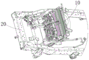
Fig. 1 is an assembly view of a heat dissipation module assembly and a vehicle frame according to a first embodiment of the present invention;
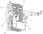
fig. 2 is a structural diagram of a heat dissipation module assembly according to a first embodiment of the present invention;
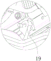
fig. 3 is a partially enlarged view of a heat dissipation module assembly according to a first embodiment of the present invention;
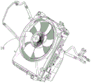
fig. 4 is an isometric view of a heat dissipation module assembly according to a first embodiment of the present invention;
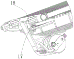
FIG. 5 is an assembly view of the condenser and clutch fan according to the first embodiment of the present invention;
description of the main element symbols:
| heat |
10 | |
16 |
| |
11 | |
17 |
| |
12 | Axial-flow type |
18 |
| |
13 | Connecting |
19 |
| |
14 | |
20 |
| Intercooler | 15 |
The following detailed description of the invention will be further described in conjunction with the above-identified drawings.
Detailed Description
In order to facilitate understanding of the present invention, the present invention will be described more fully hereinafter with reference to the accompanying drawings. Several embodiments of the invention are given in the accompanying drawings. The invention may, however, be embodied in many different forms and should not be construed as limited to the embodiments set forth herein. Rather, these embodiments are provided so that this disclosure will be thorough and complete.
It will be understood that when an element is referred to as being "secured to" another element, it can be directly on the other element or intervening elements may also be present. When an element is referred to as being "connected" to another element, it can be directly connected to the other element or intervening elements may also be present. The terms "vertical," "horizontal," "left," "right," and the like as used herein are for illustrative purposes only.
Unless defined otherwise, all technical and scientific terms used herein have the same meaning as commonly understood by one of ordinary skill in the art to which this invention belongs. The terminology used in the description of the invention herein is for the purpose of describing particular embodiments only and is not intended to be limiting of the invention. As used herein, the term "and/or" includes any and all combinations of one or more of the associated listed items.
Please refer to fig. 1, which is an assembly diagram of a heat dissipation module assembly 10 and a frame 20 according to a first embodiment of the present invention, wherein the heat dissipation module assembly 10 is fixed on the frame 20 and located under a cab, as shown in fig. 2, the heat dissipation module assembly 10 includes a radiator 12, a condenser 11, an intercooler 15 and a clutch fan 13, the radiator 12 is fixed on the frame 20, the condenser 11 and the intercooler 15 are fixed on a side surface of the radiator 12 close to the cab, the clutch fan 13 is fixed on the condenser 11, and the intercooler 15 is located under the clutch fan 13.
Specifically, four corners of the clutch fan 13 are respectively provided with a first through hole, the condenser 11 is fixed with a connecting plate 19, as shown in fig. 3, the connecting plate 19 is provided with a first connecting portion and a second connecting portion, the first connecting portion is provided with a second through hole at a position corresponding to the first through hole, and the clutch fan 13 is fixedly connected with the condenser 11 through a first bolt sequentially penetrating through the first through hole and the second through hole. Similarly, the second connecting portion is provided with a third through hole, the upper end of the intercooler 15 is provided with a third connecting portion, the third connecting portion is provided with a fourth through hole at a position corresponding to the third through hole, the radiator 12 is provided with a fifth through hole at a position corresponding to the third through hole, the intercooler 15 and the radiator 12 are fixedly connected by a second bolt sequentially penetrating through the fifth through hole, the third through hole and the fourth through hole, similarly, due to the existence of the fifth through hole and the third through hole, the lower end of the condenser 11 is fixed on the radiator 12 by a third bolt sequentially penetrating through the fifth through hole and the third through hole.
In order to fix the intercooler 15 on the radiator 12, two first brackets 14 are symmetrically and fixedly arranged at the lower end of the radiator 12, as shown in fig. 2, one end of each first bracket 14 is fixed on the radiator 12, a sixth through hole is formed in the other end of each first bracket, the intercooler 15 is provided with a fourth connecting portion, a seventh through hole is formed in the corresponding position of the sixth through hole in the fourth connecting portion, and the lower end of the intercooler 15 is fixed on the radiator 12 through a fourth bolt sequentially penetrating through the sixth through hole and the seventh through hole.
Since the components are collectively arranged, in order to increase the heat dissipation speed of the heat dissipation module assembly 10, as shown in fig. 4, an axial-flow electronic fan 18 is further fixedly arranged on the side of the heat sink 12 away from the condenser 11, and it should be noted that the axial-flow electronic fan 18 is fixedly arranged on the vehicle engine, and the axial-flow electronic fan 18 and the clutch fan 13 simultaneously dissipate heat of the components. Since the vehicle has large vibration during driving, in order to reduce the vibration, as shown in fig. 5, a spring plate 17 is fixedly disposed at a connection portion of the clutch fan 13 and the condenser 11, the spring plate 17 is sleeved on the first bolt, and a rubber cushion 16 is fixedly disposed at a connection portion of the condenser 11 and the radiator 12.
Furthermore, the heat dissipation module assembly 10 further includes a radiator 12 brace, a brace beam is fixedly disposed on one side of the radiator 12 close to the condenser 11, a frame 20 beam is fixedly disposed on the frame 20 close to the cab, one end of the radiator 12 brace is fixed on the brace beam, the other end of the radiator 12 brace is fixed on the frame 20 beam, and the radiator 12 brace is further fixed to the radiator 12.
In this embodiment, the installation process of the heat dissipation module assembly 10 is as follows: firstly, the clutch fan 13 and the condenser 11 are sequentially arranged in a penetrating manner, the first through hole is fixedly connected with a first bolt of the second through hole, then the second bolt sequentially penetrates through a fifth through hole, a third through hole and a fourth through hole to fixedly connect the intercooler 15 and the radiator 12, the lower end of the condenser 11 is fixed on the radiator 12 through a third bolt sequentially arranged in the fifth through hole and the third through hole, attention is required to be paid to the fact that the third bolt is provided with a rubber shock pad 16, then the fourth bolt is sequentially arranged in a penetrating manner through a sixth through hole and a seventh through hole to fix the lower end of the intercooler 15 on the radiator 12, finally, the radiator 12 is fixed on the frame 20, one end of a stay bar of the radiator 12 is fixed on the stay bar beam, and the other end of the radiator is fixed on the frame 20 beam. Meanwhile, an axial-flow type electronic fan 18 is mounted on the vehicle engine near a side of the radiator 12 remote from the condenser 11.
According to another aspect of the present invention, there is also provided an automobile, including the heat dissipation module assembly 10 as described above.
To sum up, the utility model discloses heat dissipation module assembly 10 in the middle of the above-mentioned embodiment, the utility model discloses simple structure, on the one hand, carry out non-standard design with heat dissipation module assembly 10, make each spare part of heat dissipation module can assemble together, and then make heat dissipation module assembly 10 structure compacter, the space utilization of frame 20 has been improved, the repacking degree of difficulty of vehicle has been reduced, and simultaneously, fix heat dissipation module assembly 10 in the driver's cabin below, it is great to make frame 20 rear space, make things convenient for later stage vehicle repacking, on the other hand, spring leaf 17 and rubber shock pad 16's setting, the vibrations to heat dissipation module assembly 10 among the vehicle driving process have been reduced, and simultaneously, axial-flow type electronic fan 18's setting has improved heat dissipation module assembly 10's rate.
The above-mentioned embodiments only represent some embodiments of the present invention, and the description thereof is specific and detailed, but not to be construed as limiting the scope of the present invention. It should be noted that, for those skilled in the art, without departing from the spirit of the present invention, several variations and modifications can be made, which are within the scope of the present invention. Therefore, the protection scope of the present invention should be subject to the appended claims.
Claims (7)
1. A heat dissipation module assembly is fixed on a frame and comprises a radiator, a condenser, an intercooler and a clutch fan, and is characterized in that the heat dissipation module assembly is positioned below a cab, the radiator is fixed on the frame, the intercooler is positioned below the clutch fan, first through holes are respectively arranged at four corners of the clutch fan, the condenser is fixedly provided with a connecting plate which comprises a first connecting part and a second connecting part which are connected, the first connecting part is provided with a second through hole at a position corresponding to the first through hole, the clutch fan and the condenser are fixedly connected through first bolts sequentially penetrating the first through hole and the second through hole, the second connecting part is provided with a third through hole, a third connecting part is arranged at the upper end of the intercooler, and a fourth through hole is arranged at a position corresponding to the third through hole, the radiator is in the third through-hole corresponds the position and is equipped with the fifth through-hole, the intercooler with the radiator is through wearing to locate in proper order the fifth through-hole the third through-hole and the second bolt fixed connection of fourth through-hole, the condenser lower extreme is through wearing to locate in proper order the fifth through-hole and the third bolt of third through-hole is fixed on the radiator.
2. The assembly as claimed in claim 1, wherein two first brackets are symmetrically fixed to the lower end of the heat sink, one end of each first bracket is fixed to the heat sink, the other end of each first bracket is provided with a sixth through hole, the intercooler is provided with a fourth connecting portion, the fourth connecting portion is provided with a seventh through hole at a position corresponding to the sixth through hole, and the lower end of the intercooler is fixed to the heat sink by a fourth bolt sequentially passing through the sixth through hole and the seventh through hole.
3. The assembly according to claim 1, wherein an axial-flow electronic fan is mounted on a side of the heat sink away from the condenser.
4. The assembly as claimed in claim 1, wherein a spring plate is fixed at a connection between the clutch fan and the condenser, and the spring plate is disposed on the first bolt.
5. The assembly according to claim 1, wherein a rubber cushion is fixed at a connection between the condenser and the heat sink.
6. The thermal module assembly of claim 1, further comprising a radiator support rod, wherein a support rod cross member is fixed on a side of the radiator adjacent to the condenser, a frame cross member is fixed on the frame adjacent to the cab, and one end of the radiator support rod is fixed on the support rod cross member and the other end of the radiator support rod is fixed on the frame cross member.
7. An automobile, characterized by comprising the heat dissipation module assembly according to any one of claims 1 to 6.
Priority Applications (1)
| Application Number | Priority Date | Filing Date | Title |
|---|---|---|---|
| CN202021395843.3U CN212708922U (en) | 2020-07-15 | 2020-07-15 | Heat dissipation module assembly and automobile |
Applications Claiming Priority (1)
| Application Number | Priority Date | Filing Date | Title |
|---|---|---|---|
| CN202021395843.3U CN212708922U (en) | 2020-07-15 | 2020-07-15 | Heat dissipation module assembly and automobile |
Publications (1)
| Publication Number | Publication Date |
|---|---|
| CN212708922U true CN212708922U (en) | 2021-03-16 |
Family
ID=74906358
Family Applications (1)
| Application Number | Title | Priority Date | Filing Date |
|---|---|---|---|
| CN202021395843.3U Active CN212708922U (en) | 2020-07-15 | 2020-07-15 | Heat dissipation module assembly and automobile |
Country Status (1)
| Country | Link |
|---|---|
| CN (1) | CN212708922U (en) |
-
2020
- 2020-07-15 CN CN202021395843.3U patent/CN212708922U/en active Active
Similar Documents
| Publication | Publication Date | Title |
|---|---|---|
| CN205207080U (en) | Integrated multi -functional air condition compressor support | |
| CN216733816U (en) | Air conditioner compressor assembly for vehicle and vehicle | |
| CN212708922U (en) | Heat dissipation module assembly and automobile | |
| JPH10227213A (en) | Supporting device for vehicle cooler | |
| CN215321960U (en) | Multifunctional integrated suspension bracket | |
| CN216268570U (en) | Air condition compressor installation fixing device and vehicle | |
| KR20170050099A (en) | Support structure for air conditioner unit in bus | |
| CN213892163U (en) | Integrated radiating fan assembly and automobile | |
| CN108407595B (en) | Power assembly suspension of truck system | |
| CN210706849U (en) | Power assembly suspension and vehicle applying same | |
| WO2021116650A1 (en) | Mount on inverter housing | |
| CN219115191U (en) | Mounting structure of automobile air conditioner compressor | |
| CN215398140U (en) | Right suspension support assembly and car | |
| CN113899233B (en) | Automobile, cooling system thereof and intercooling cooling device | |
| CN110821649B (en) | Support structure of engine air conditioner compressor | |
| CN210363335U (en) | Motor suspension and air condition compressor coupling assembling | |
| US20180362086A1 (en) | Motor vehicle assembly incorporating a front end module, a front suspension and a sorb structure | |
| CN209492352U (en) | The fixation device of new-energy automobile overhead condenser | |
| EP4261062A1 (en) | Suspension system for vehicle air conditioner compressor, and vehicle | |
| CN217300824U (en) | Compressor and drive arrangement's of car assembly and car | |
| CN212709703U (en) | Middle-sized commercial car driver's cabin front suspension structure | |
| CN214984782U (en) | Suspension structure capable of integrating whole vehicle wire harness installation position | |
| CN219172171U (en) | Suspension assembly and vehicle | |
| CN218316162U (en) | Vibration isolation support for compressor | |
| CN212615526U (en) | Energy-saving integrated double-fan of automobile radiator |
Legal Events
| Date | Code | Title | Description |
|---|---|---|---|
| GR01 | Patent grant | ||
| GR01 | Patent grant |