CN212090714U - Old person's rehabilitation nursing tempers device - Google Patents
Old person's rehabilitation nursing tempers device Download PDFInfo
- Publication number
- CN212090714U CN212090714U CN202020585233.3U CN202020585233U CN212090714U CN 212090714 U CN212090714 U CN 212090714U CN 202020585233 U CN202020585233 U CN 202020585233U CN 212090714 U CN212090714 U CN 212090714U
- Authority
- CN
- China
- Prior art keywords
- massage
- fixedly connected
- plate
- bevel gear
- box
- Prior art date
- Legal status (The legal status is an assumption and is not a legal conclusion. Google has not performed a legal analysis and makes no representation as to the accuracy of the status listed.)
- Expired - Fee Related
Links
Images


Abstract
The rehabilitation nursing exercise device for the old comprises a console, wherein the left side and the right side of the surface of the front end in the console are respectively and fixedly connected with a massage box, the massage box is internally provided with a massage device, the front end of the console is fixedly connected with a seat plate, the front end of the seat plate is fixedly connected with a mounting plate, the left side and the right side of the upper end of the mounting plate are respectively provided with a rotatable connecting plate, and a bevel gear transmission mechanism is connected between the connecting plates and the massage device; the user can sit on the seat surface and lie on the control cabinet surface when using this device to take exercise, can step on the running-board with the foot and carry out the circular rotation activity and temper both legs when the user lies on the control cabinet surface, step on the running-board when rotating alright drive massage device work through bevel gear drive mechanism when the user, make massage device massage user's back, not only increased the interest of this device, still increased the enthusiasm that the user initiatively taken exercise.
Description
Technical Field
The utility model belongs to the medical equipment field, concretely relates to old person's rehabilitation and nursing tempers device.
Background
The hospital is in the treatment process to the patient in order to promote the flexibility of patient's limbs and to promote the recovery of patient's state of an illness, it carries out appropriate rehabilitation exercise to need to let patient usually, in order to promote the recovery of patient's physical function, especially, it is ageing to old person's limbs rigidity, degree of relative flexibility is poor, carry out the more indispensable link of rehabilitation exercise, the apparatus function of the rehabilitation exercise that the patient used at present is more single relatively, and interesting poor, the old man hardly persists for a long time in the easy middle-term of the in-process of rehabilitation exercise, can't effectively reach anticipated effect, be unfavorable for the recovery of patient's state of.
SUMMERY OF THE UTILITY MODEL
To the above situation, for overcoming prior art's defect, the utility model provides an old person's rehabilitation nursing exercise device, the effectual old person of having solved uses present rehabilitation exercise apparatus difficult long-term the in-process of carrying out the rehabilitation exercise hardly insists on for a long time, can't effectively reach anticipated effect, is unfavorable for the problem of the recovery of the patient's state of an illness.
In order to solve the above problems, the utility model adopts the following technical proposal:
the rehabilitation nursing exercise device for the old comprises a console, wherein the left side and the right side of the surface of the front end in the console are respectively and fixedly connected with a massage box, the massage device is installed in the massage box, the front end of the console is fixedly connected with a seat, the front end of the seat is fixedly connected with an installation plate, the left side and the right side of the upper end of the installation plate are respectively provided with a rotatable connection plate, the outer ends of the two connection plates are fixedly connected with pedals, a bevel gear transmission mechanism is connected between the connection plates and the massage device, and when the connection plates rotate, the working structure of the massage device can be formed;
the massage device comprises a plurality of rotatable cams, the cams are respectively installed inside the massage box, each massage column capable of moving up and down is respectively installed at the upper end corresponding to each cam, each massage rod capable of moving up and down is respectively installed inside each massage column, each massage rod protrudes out of the upper end surface of each massage column, and when the cams rotate, a structure that the plurality of massage columns respectively move up and down can be formed.
Preferably, the interior of the massage box is respectively and rotatably connected with a main massage shaft, two sides of the main massage shaft are respectively provided with a rotatable auxiliary massage shaft, two ends of the auxiliary massage shaft are respectively and rotatably connected with the inner wall of the massage box, and the cams are fixedly connected to the surfaces of the main massage shaft and the auxiliary massage shaft; the front ends of the main massage shaft and the auxiliary massage shaft are fixedly connected with a linkage plate, the front side of the linkage plate is provided with a linkage rod, and the edge of the right side of the front end surface of the linkage plate is hinged with the linkage rod respectively.
Preferably, the massage box on the left side of the console and the massage box on the right side of the console are sequentially provided with a driven pinion and a second belt wheel respectively in the middle of the rear end of the massage box, the massage box on the left side and the right side of the console are internally provided with the rear ends of main massage shafts which respectively penetrate through the rear end surface of the massage box, the rear ends of the main massage shafts are respectively fixedly connected with the driven pinion and the second belt wheel, the rear end of the driven pinion is coaxially and fixedly connected with a first belt wheel, the first belt wheel is connected with the second belt wheel through a belt, the left side of the driven pinion is meshed with a transmission gear wheel, the rear end of the transmission gear wheel is coaxially and fixedly connected with a fifth connection bevel gear, and the fifth connection bevel gear is connected with a bevel gear transmission mechanism.
Preferably, the upper end of the interior of the massage box is provided with a spring groove, the upper end and the lower end of the spring groove are provided with first sliding holes, the massage columns are respectively connected with the first sliding holes in a sliding manner, the interior of the spring groove is provided with a first return spring, the upper end of the first return spring is respectively fixedly connected with the upper end of the interior of the spring groove, the surface of each massage column is fixedly connected with a first spring baffle, and the lower end of the first return spring is respectively fixedly connected with the first spring baffle; the massage pole is characterized in that a second spring groove is formed in the massage pole, second sliding holes are formed in the upper end of the second spring groove respectively, the massage pole is connected with the second sliding holes in a sliding mode respectively, a second spring baffle plate with the same diameter as the second spring groove is fixedly connected to the lower end of the massage pole, a second reset spring is fixedly connected to the lower end of the second spring baffle plate respectively, and the lower end of the second reset spring is fixedly connected with the lower end of the inner portion of the second spring groove respectively.
Preferably, the rear end fixedly connected with fixed plate of control cabinet, the upper end fixedly connected with spliced pole of fixed plate, the upper end fixedly connected with roof of spliced pole, the left and right sides of roof lower extreme surface is fixedly connected with respectively and connects the rope, the lower extreme fixedly connected with who connects the rope hangs the handle, the rear end fixedly connected with bottom plate of fixed plate, the upper end of bottom plate is rotated and is connected with the rotor plate.
The utility model discloses novel structure, think about ingenious, easy operation is convenient, compares with prior art and has following advantage:
the user can sit on the seat surface and lie on the control cabinet surface when using this device to take exercise, seat fixed surface connects elastic rubber pad, a comfort level when being used for increasing the user, the user can step on the running-board with the foot and carry out the circular rotation activity and temper both legs when lying on the control cabinet surface, when the user steps on the running-board and rotate alright drive massage device work through bevel gear drive mechanism, make massage device massage user's back, not only increased the interest of this device, the enthusiasm of user's initiative exercise has still been increased, and the user can also grasp through both hands and hang the handle and do the motion of hanging and extend limbs, and can also step on the rotor plate with the foot and twist the waist when grasping and hanging the handle, temper the waist, the function is various.
Drawings
Fig. 1 is the utility model discloses an overall structure schematic diagram of device is tempered in old person's rehabilitation nursing.
Fig. 2 is the utility model discloses an overall structure rear view schematic diagram of device is tempered in old person's rehabilitation nursing.
Fig. 3 is the utility model discloses a console inner structure profile view schematic diagram of old person's rehabilitation and nursing exercise device.
Fig. 4 is the utility model discloses a bevel gear drive mechanism schematic diagram of device is tempered in old person's rehabilitation nursing.
Fig. 5 is the utility model discloses a device is tempered in old person's rehabilitation nursing's first band pulley and second band pulley connection structure sketch map.
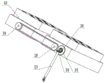
Fig. 6 is the utility model discloses a massage box internal structure profile schematic diagram of device is tempered in old person's rehabilitation.
Fig. 7 is the utility model discloses a device is tempered in old person's rehabilitation nursing's cam mounting structure sketch map.
Fig. 8 is the utility model discloses a device is tempered in old person's rehabilitation nursing massage post mounting structure sketch map.
Fig. 9 is the utility model discloses a massage post inner structure section view schematic diagram of device is tempered in old person's rehabilitation.
In the figure: 1-console, 2-fixed plate, 3-connecting column, 4-top plate, 5-bottom plate, 6-rotating plate, 7-suspension handle, 8-seat plate, 9-mounting plate, 10-first connecting shaft, 11-first steering bevel gear, 12-second steering bevel gear, 13-third steering bevel gear, 14-fourth steering bevel gear, 15-connecting plate, 16-pedal, 17-first transmission rod, 18-fifth steering bevel gear, 19-first connecting bevel gear, 20-second connecting bevel gear, 21-third connecting bevel gear, 22-second transmission rod, 23-third transmission rod, 24-fourth connecting bevel gear, 25-fifth connecting bevel gear, 26-transmission gearwheel, 27-driven pinion, 28-first belt wheel, 29-second belt wheel, 30-main massage shaft, 31-auxiliary massage shaft, 32-linkage plate, 33-linkage rod, 35-massage column, 36-first spring baffle, 37-first return spring, 39-massage rod, 40-second return spring, 41-second spring baffle, 42-massage box and 43-cam.
Detailed Description
The following are specific embodiments of the present invention, and the technical solutions of the present invention will be further described with reference to the accompanying drawings, but the present invention is not limited to these embodiments.
As shown in fig. 1-9, the utility model provides an old person rehabilitation nursing exercise device, including control cabinet 1, the left and right sides of the inside front end surface of control cabinet 1 is fixedly connected with massage box 42 respectively, massage device is installed to massage box 42 internally, the front end of control cabinet 1 is fixedly connected with seat 8, the front end of seat 8 is fixedly connected with mounting panel 9, the rotatable connecting plate 15 is installed respectively to the upper end left and right sides of mounting panel 9, two the outer end of connecting plate 15 is fixedly connected with running-board 16, be connected with bevel gear drive mechanism between connecting plate 15 and the massage device, can constitute the structure of massage device work when connecting plate 15 rotates;
the massage device comprises a plurality of rotatable cams 43, the cams 43 are respectively arranged in the massage box 42, the upper end corresponding to each cam 43 is respectively provided with a massage column 35 capable of moving up and down, the inner part of each massage column 35 is respectively provided with a massage rod 39 capable of moving up and down, the massage rod 39 protrudes out of the upper end surface of the massage column 35, and when the plurality of cams 43 rotate, a structure that the plurality of massage columns 35 respectively move up and down can be formed.
When the device is used for exercise, a user can sit on the surface of the seat plate 8 and lie on the surface of the control table 1, the surface of the seat plate 8 is fixedly connected with an elastic rubber pad for increasing the comfort level of the user during use, the user can step on the pedal plate 16 with feet when lying on the surface of the control table 1 and do circular rotation movement and exercise on two legs, and when the user steps on the pedal plate 16 and rotates, the massage device can be driven to work through the bevel gear transmission mechanism, so that the massage device can massage the back of the user, the interestingness of the device is increased, the initiative of active exercise of the user is increased, and the device has various functions; when the user rotates the legs by stepping on the pedals 16, the bevel gear transmission mechanism can drive the cams 43 to rotate and continuously jack up the massage column 35, so that the upper end of the massage rod 39 contacts with the back of the user to massage the back of the user.
The interior of the massage box 42 is respectively and rotatably connected with a main massage shaft 30, two sides of the main massage shaft 30 are respectively provided with a rotatable auxiliary massage shaft 31, two ends of the auxiliary massage shaft 31 are respectively and rotatably connected with the inner wall of the massage box 42, and the cam 43 is fixedly connected with the surfaces of the main massage shaft 30 and the auxiliary massage shaft 31; the front ends of the main massage shaft 30 and the auxiliary massage shaft 31 are both fixedly connected with a linkage plate 32, the front side of the linkage plate 32 is provided with a linkage rod 33, and the right side edge of the front end surface of the linkage plate 32 is respectively hinged with the linkage rod 33.
The massage device is characterized in that a driven pinion 27 and a second belt wheel 29 are sequentially arranged in the middle of the rear end of the massage box 42 on the left side of the console 1 and the middle of the rear end of the massage box 42 on the right side of the console 1, the rear ends of the main massage shafts 30 inside the massage boxes 42 on the left side and the right side of the console 1 respectively penetrate through the surface of the rear end of the massage box 42, the rear ends of the two main massage shafts 30 are fixedly connected with the driven pinion 27 and the second belt wheel 29 respectively, a first belt wheel 28 is coaxially and fixedly connected with the rear end of the driven pinion 27, the first belt wheel 28 is connected with the second belt wheel 29 through a belt, a transmission large gear 26 is meshed on the left side of the driven pinion 27, a fifth connection bevel gear 25 is coaxially and fixedly connected with the rear end of the transmission large gear 26, and the fifth connection bevel gear 25.
The surface of the second belt wheel 29 is sleeved with a transmission belt, the other end of the transmission belt is sleeved on the surface of the first belt wheel 28, the linkage plate 32 and the linkage rod 33 are used for transmitting the power of the main massage shaft 30 to the auxiliary massage shaft 31, so that the main massage shaft 30 and the auxiliary massage shaft 31 can rotate simultaneously, the first belt wheel 28 and the second belt wheel 29 are used for enabling the two main massage shafts 30 to rotate simultaneously, so that the force transmitted by the bevel gear transmission mechanism can simultaneously drive the two main massage shafts 30 to rotate through the meshing with the fifth connecting bevel gear 25 and the meshing of the transmission large gear 26 and the driven small gear 27, wherein the transmission large gear 26 can accelerate the driven small gear 27 when driving the driven small gear 27 to rotate, so that the up-and-down movement speed of the massage column 35 is accelerated, and the user can fully feel the effect brought by the massage device, and as shown in the seventh figure, the installation state of the cams 43 on the surfaces of each main massage shaft 30 and the auxiliary, the plurality of massage columns 35 can be moved up and down continuously to enhance the massage effect.
The upper end of the interior of the massage box 42 is provided with a spring groove, the upper end and the lower end of the spring groove are provided with first sliding holes, the massage column 35 is respectively connected with the first sliding holes in a sliding manner, the interior of the spring groove is provided with a first return spring 37, the upper end of the first return spring 37 is respectively fixedly connected with the upper end of the interior of the spring groove, the surface of the massage column 35 is respectively fixedly connected with a first spring baffle 36, and the lower end of the first return spring 37 is respectively fixedly connected with the first spring baffle 36; the massage column 35 is provided with a second spring groove, the upper end of the second spring groove is provided with a second sliding hole respectively, the massage rods 39 are connected with the second sliding hole in a sliding manner respectively, the lower ends of the massage rods 39 are fixedly connected with a second spring baffle 41 with the same diameter as the second spring groove, the lower ends of the second spring baffle 41 are fixedly connected with a second return spring 40 respectively, and the lower ends of the second return spring 40 are fixedly connected with the lower end of the inner part of the second spring groove respectively.
The cambered surface has been seted up to the lower extreme of massage post 35, be used for cooperating with cam 43, first spring baffle 36 and second spring baffle 41 are used for extrudeing first reset spring 37 and second reset spring 40 respectively, and be used for preventing that massage post 35 and massage pole 39 break away from first slide opening and second slide opening, first reset spring 37 and second reset spring 40 are used for promoting massage post 35 and massage pole 39 respectively and reset, the upper end of massage pole 39 is the spherical structure, be used for clicking patient's health, provide the comfort level of massage, and massage pole 39 atress can be moved down and extrude second reset spring 40 when upwards moving is used for patient's health contact, through the elasticity of second reset spring 40 to patient's health application of force, comfort level when improving the massage to the patient.
As shown in the figure four, the bevel gear transmission mechanism comprises a first connecting shaft 10, the mounting plate 9 is hollow, two ends of the first connecting shaft 10 are respectively rotatably connected with the inner wall of the mounting plate 9, a first steering bevel gear 11 is fixedly connected to the surface of the first connecting shaft 10, a second steering bevel gear 12 is meshed with the lower end of the first steering bevel gear 11, a first transmission shaft is fixedly connected to the middle of the second steering bevel gear 12, the first transmission shaft is rotatably connected with the inner wall of the mounting plate 9, a third steering bevel gear 13 is fixedly connected to the lower end of the transmission shaft, a fourth steering bevel gear 14 is meshed with the rear side of the third steering bevel gear 13, a first transmission rod 17 is fixedly connected to the middle of the fourth steering bevel gear 14, the rear end of the first transmission rod 17 penetrates through the mounting plate 9, the seat plate 8 and the console 1 and the rear end of the first transmission rod 17 is rotatably connected with the inner wall of the console 1, a fifth steering bevel gear 18 is fixedly connected to, a first connecting bevel gear 19 is engaged on the left side of a fifth steering bevel gear 18, a second transmission shaft is fixedly connected to the middle of a fifth connecting bevel gear 25, the second transmission shaft is rotatably connected to the inner wall of the console 1, a second connecting bevel gear 20 is fixedly connected to the left side of the second transmission shaft, a third connecting bevel gear 21 is engaged on the left side of the second connecting bevel gear 20, a second transmission rod 22 is fixedly connected to the middle of the third connecting bevel gear 21, the second transmission rod 22 is rotatably connected to the inner wall of the console 1, a universal joint is fixedly connected to the upper end of the second transmission rod 22, a third transmission rod 23 is fixedly connected to the other end of the universal joint, the third transmission rod 23 is rotatably connected to the inner wall of the console 1, a fourth connecting bevel gear 24 is fixedly connected to the other end of the third transmission rod 23, the fourth connecting bevel gear 24 is engaged with the fifth connecting bevel gear 25, and the first connecting, when the first connecting shaft 10 rotates, it can be steered and driven by the bevel gear transmission mechanism, and the power is transmitted to the fifth connecting bevel gear 25, thereby rotating the two main massage shafts 30.
The rear end fixedly connected with fixed plate 2 of control cabinet 1, the upper end fixedly connected with spliced pole 3 of fixed plate 2, the upper end fixedly connected with roof 4 of spliced pole 3, the left and right sides on 4 lower extreme surfaces of roof fixedly connected with respectively connects the rope, the lower extreme fixedly connected with who connects the rope hangs handle 7, the rear end fixedly connected with bottom plate 5 of fixed plate 2, the upper end of bottom plate 5 is rotated and is connected with rotor plate 6.
The user can grasp through both hands and hang handle 7 and do and hang the motion and extend limbs to can also step on rotor plate 6 with the foot and twist the waist when grasping hanging handle 7, temper the waist, the equal fixedly connected with landing leg in the left and right sides of bottom plate 5 rear end and 1 front side of control cabinet for support this device.
The utility model discloses a working process does:
the utility model discloses when using, the user can sit on seat 8 surfaces, lie in 1 surface of control cabinet and step on running-board 16 with the foot and rotate, the activity with temper the both legs, can drive the massage device operation and massage user's back in the activity both legs, strengthen comfort level and interest that the user tempered, the enthusiasm that the reinforcing user tempered, and the user can also stand and hold through both hands and hang handle 7 and be the suspension motion on rotor plate 6, and can also rotate and temper the waist.
The specific embodiments described herein are merely illustrative of the spirit of the invention. Various modifications or additions may be made to the described embodiments or alternatives may be employed by those skilled in the art without departing from the spirit or scope of the invention as defined in the appended claims.
Claims (5)
1. Device is tempered in old person's rehabilitation nursing, including control cabinet (1), its characterized in that: the left side and the right side of the surface of the front end in the console (1) are respectively and fixedly connected with a massage box (42), a massage device is arranged in each massage box (42), the front end of the console (1) is fixedly connected with a seat (8), the front end of the seat (8) is fixedly connected with a mounting plate (9), the left side and the right side of the upper end of the mounting plate (9) are respectively provided with a rotatable connecting plate (15), the outer ends of the two connecting plates (15) are fixedly connected with pedals (16), a bevel gear transmission mechanism is connected between each connecting plate (15) and the massage device, and when the connecting plates (15) rotate, a working structure of the massage device can be formed;
the massage device is including a plurality of rotatable cams (43), install respectively cam (43) inside massage box (42), every massage post (35) that can reciprocate are installed respectively to the corresponding upper end of cam (43), every massage pole (39) that can reciprocate are installed respectively to the inside of massage post (35), massage pole (39) all are outstanding massage post (35) upper end surface can constitute the structure that a plurality of massage posts (35) reciprocated respectively when cam (43) rotates.
2. The elderly rehabilitation and care exercise device of claim 1, wherein: the inner part of the massage box (42) is respectively and rotatably connected with a main massage shaft (30), two sides of the main massage shaft (30) are respectively provided with a rotatable auxiliary massage shaft (31), two ends of the auxiliary massage shaft (31) are respectively and rotatably connected with the inner wall of the massage box (42), and the cams (43) are fixedly connected to the surfaces of the main massage shaft (30) and the auxiliary massage shaft (31); the front ends of the main massage shaft (30) and the auxiliary massage shaft (31) are fixedly connected with a linkage plate (32), the front side of the linkage plate (32) is provided with a linkage rod (33), and the edge of the right side of the front end surface of the linkage plate (32) is hinged with the linkage rod (33) respectively.
3. The elderly rehabilitation and care exercise device of claim 2, wherein: a driven pinion (27) and a second belt wheel (29) are sequentially arranged in the middle of the rear end of the massage box (42) on the left side of the console (1) and the middle of the rear end of the massage box (42) on the right side of the console (1), the rear ends of the main massage shafts (30) in the massage box (42) on the left side and the right side of the console (1) respectively penetrate through the surface of the rear end of the massage box (42), the rear ends of the two main massage shafts (30) are fixedly connected with the driven pinion (27) and the second belt wheel (29) respectively, a first belt wheel (28) is coaxially and fixedly connected with the rear end of the driven pinion (27), the first belt wheel (28) is connected with the second belt wheel (29) through a belt, a transmission large gear (26) is meshed with the left side of the driven pinion (27), a fifth connecting bevel gear (25) is coaxially and fixedly connected with the rear end of the transmission large gear (26), and the fifth connecting bevel gear (25) is connected with the bevel gear transmission mechanism.
4. The elderly rehabilitation and care exercise device of claim 3, wherein: the upper end of the interior of the massage box (42) is provided with a spring groove, the upper end and the lower end of the spring groove are provided with first sliding holes, the massage columns (35) are respectively in sliding connection with the first sliding holes, first return springs (37) are arranged in the spring groove, the upper ends of the first return springs (37) are respectively fixedly connected with the upper end of the interior of the spring groove, the surfaces of the massage columns (35) are respectively fixedly connected with first spring baffles (36), and the lower ends of the first return springs (37) are respectively fixedly connected with the first spring baffles (36); the massage pole (35) inside has been seted up the second spring groove, the second slide opening has been seted up respectively to the upper end in second spring groove, massage pole (39) respectively sliding connection with second slide opening sliding connection, the lower extreme fixedly connected with of massage pole (39) with second spring baffle (41) that second spring groove diameter equals, the lower extreme of second spring baffle (41) is fixed connection second reset spring (40) respectively, the lower extreme of second reset spring (40) respectively with the inside lower extreme fixed connection in second spring groove.
5. The elderly rehabilitation and care exercise device of claim 1, wherein: the rear end fixedly connected with fixed plate (2) of control cabinet (1), upper end fixedly connected with spliced pole (3) of fixed plate (2), upper end fixedly connected with roof (4) of spliced pole (3), the left and right sides difference fixedly connected with on roof (4) lower extreme surface connects the rope, the lower extreme fixedly connected with of connecting the rope hangs handle (7), the rear end fixedly connected with bottom plate (5) of fixed plate (2), the upper end of bottom plate (5) is rotated and is connected with rotor plate (6).
Priority Applications (1)
| Application Number | Priority Date | Filing Date | Title |
|---|---|---|---|
| CN202020585233.3U CN212090714U (en) | 2020-04-17 | 2020-04-17 | Old person's rehabilitation nursing tempers device |
Applications Claiming Priority (1)
| Application Number | Priority Date | Filing Date | Title |
|---|---|---|---|
| CN202020585233.3U CN212090714U (en) | 2020-04-17 | 2020-04-17 | Old person's rehabilitation nursing tempers device |
Publications (1)
| Publication Number | Publication Date |
|---|---|
| CN212090714U true CN212090714U (en) | 2020-12-08 |
Family
ID=73641040
Family Applications (1)
| Application Number | Title | Priority Date | Filing Date |
|---|---|---|---|
| CN202020585233.3U Expired - Fee Related CN212090714U (en) | 2020-04-17 | 2020-04-17 | Old person's rehabilitation nursing tempers device |
Country Status (1)
| Country | Link |
|---|---|
| CN (1) | CN212090714U (en) |
Cited By (3)
| Publication number | Priority date | Publication date | Assignee | Title |
|---|---|---|---|---|
| CN112587875A (en) * | 2020-12-28 | 2021-04-02 | 杭州喜达医疗科技有限公司 | Can carry out training device for department of rehabilitation that whole body coordinates to take exercise |
| CN112999583A (en) * | 2021-03-18 | 2021-06-22 | 扬州大学附属医院 | A temper device for cardiovascular internal medicine is clinical |
| CN113425557A (en) * | 2021-07-21 | 2021-09-24 | 新疆维吾尔自治区人民医院 | Old man nurses device based on thing networking |
-
2020
- 2020-04-17 CN CN202020585233.3U patent/CN212090714U/en not_active Expired - Fee Related
Cited By (4)
| Publication number | Priority date | Publication date | Assignee | Title |
|---|---|---|---|---|
| CN112587875A (en) * | 2020-12-28 | 2021-04-02 | 杭州喜达医疗科技有限公司 | Can carry out training device for department of rehabilitation that whole body coordinates to take exercise |
| CN112999583A (en) * | 2021-03-18 | 2021-06-22 | 扬州大学附属医院 | A temper device for cardiovascular internal medicine is clinical |
| CN113425557A (en) * | 2021-07-21 | 2021-09-24 | 新疆维吾尔自治区人民医院 | Old man nurses device based on thing networking |
| CN113425557B (en) * | 2021-07-21 | 2022-10-28 | 新疆维吾尔自治区人民医院 | Old man nurses device based on thing networking |
Similar Documents
| Publication | Publication Date | Title |
|---|---|---|
| CN212090714U (en) | Old person's rehabilitation nursing tempers device | |
| CN206777438U (en) | It is a kind of for orthopedic spinal treatment and rehabilitation it is function bed | |
| CN109260671A (en) | A kind of passive hand device for healing and training of master | |
| CN110638618A (en) | Uropoiesis surgery nursing device | |
| CN111513989A (en) | Internal medicine nursing exercise device | |
| CN108354783A (en) | A kind of movable type upper limb recovering aid robot | |
| CN111616921B (en) | Wrist training device driven by connecting rod reciprocating mechanism | |
| CN112932903A (en) | Cerebral apoplexy rehabilitation exercise device | |
| CN114305898A (en) | Neurosurgery limbs rehabilitation training device | |
| CN213465894U (en) | Exoskeleton mechanical arm and upper limb rehabilitation training device | |
| CN210991667U (en) | Department of neurology nurses massage bed | |
| CN112618271A (en) | Medical lower limb rehabilitation exercise device for severe patients | |
| CN108836737B (en) | Rehabilitation training device | |
| CN215609148U (en) | Department of neurology rehabilitation training device | |
| CN203841873U (en) | Lumbar disc herniation treatment device | |
| CN215132871U (en) | Low limbs massage device is used in big nursing | |
| CN211912580U (en) | Rehabilitation training auxiliary device | |
| CN213642005U (en) | Patient body massaging device for neurology nursing | |
| CN211067943U (en) | Outpatient nursing massage device | |
| CN108479001B (en) | Device for driving part of limbs to actively move to drive other limbs to move | |
| CN106420258B (en) | One kind is help the disabled standing rehabilitation frame | |
| CN215536231U (en) | Traditional Chinese medicine rehabilitation physiotherapy nursing device for cardiovascular internal medicine | |
| CN213099258U (en) | Traditional chinese medical science nursing is with route reason unblock striking rehabilitation ware | |
| CN214019063U (en) | Multifunctional integrated nursing practical device for old people | |
| CN112168613A (en) | Shank rehabilitation device |
Legal Events
| Date | Code | Title | Description |
|---|---|---|---|
| GR01 | Patent grant | ||
| GR01 | Patent grant | ||
| CF01 | Termination of patent right due to non-payment of annual fee |
Granted publication date: 20201208 |
|
| CF01 | Termination of patent right due to non-payment of annual fee |