CN211026491U - Garbage processor - Google Patents
Garbage processor Download PDFInfo
- Publication number
- CN211026491U CN211026491U CN201921890842.3U CN201921890842U CN211026491U CN 211026491 U CN211026491 U CN 211026491U CN 201921890842 U CN201921890842 U CN 201921890842U CN 211026491 U CN211026491 U CN 211026491U
- Authority
- CN
- China
- Prior art keywords
- crushing
- driving motor
- fixedly connected
- drying
- handling
- Prior art date
- Legal status (The legal status is an assumption and is not a legal conclusion. Google has not performed a legal analysis and makes no representation as to the accuracy of the status listed.)
- Active
Links
Images


Landscapes
- Crushing And Pulverization Processes (AREA)
- Processing Of Solid Wastes (AREA)
Abstract
The utility model discloses a garbage disposer relates to refuse treatment technical field, and is too simple for solving the garbage disposer structure on the present market, and the solid in the rubbish can not completely separate with liquid, and then also is not enough abundant to the processing of rubbish, the problem of the collection to solid waste of also being convenient for simultaneously. One side of handling the roof end is provided with the switch, the upper end of handling incasement portion is provided with crushing mechanism, the below that the inside of handling the case is located the scraper blade is provided with rubbing crusher and constructs, the below that the inside of handling the case is located the baffle box is provided with compressing mechanism, the opposite side that the inside of handling the case is located compressing mechanism below is provided with drying mechanism, the below that the inside of handling the case is located the water receiving tank is provided with the water receiving tank, the inside fixedly connected with limiting plate of water receiving tank, the upper end that the inside of water receiving tank is located the limiting plate is provided with the activated carbon board, the below that the inside of handling the case is located drying mechanism is provided with the material.
Description
Technical Field
The utility model relates to a refuse handling installation technical field specifically is a refuse treatment ware.
Background
Garbage is a waste product which loses use value and cannot be utilized, is an important link of material circulation, and is solid and fluid material which is not needed or useless. Garbage can be broadly classified into industrial garbage and domestic garbage, wherein the domestic garbage is waste generated in daily life of people, and is generally discarded and cleaned by a unified organization, or is individually treated by a garbage disposer.
The garbage disposer on the market at present has a too simple structure, the solid and the liquid in the garbage can not be completely separated, the garbage can be further not sufficiently treated, and meanwhile, the collection of the solid garbage is not convenient, so that the problem is urgently needed to be solved by the garbage disposer on the market.
SUMMERY OF THE UTILITY MODEL
An object of the utility model is to provide a garbage disposer to solve among the above-mentioned background art garbage disposer structure on the market at present too simple, the solid in the rubbish can not completely separate with liquid, and then also not enough abundant to the processing of rubbish, the problem of the collection to solid rubbish of also being convenient for simultaneously.
In order to achieve the above object, the utility model provides a following technical scheme: a garbage processor comprises a processing box, wherein one side of the top end of the processing box is provided with a switch, the other side of the top end of the processing box is provided with a control device, the rear end of the processing box is sequentially provided with a throwing-in port cover plate and a throwing-in plate from top to bottom, the upper end inside the processing box is provided with a crushing mechanism, the inside of the processing box is positioned below the crushing mechanism and is fixedly connected with a scraper blade, the inside of the processing box is positioned below the scraper blade and is provided with a crushing mechanism, the inside of the processing box is positioned below the crushing mechanism and is fixedly connected with a guide chute, the inside of the processing box is positioned below the guide chute and is provided with a compression mechanism, one side of the inside of the processing box, which is positioned below the compression mechanism, is fixedly connected with a water receiving tank, the other side of the inside of the processing box, which is positioned below the water, receive the inside fixedly connected with limiting plate of water tank, the inside upper end that is located the limiting plate of receiving the water tank is provided with the activated carbon board, the inside below that is located drying mechanism of handling the case is provided with and receives the workbin.
Preferably, crushing mechanism includes the crushing roller, the one end transmission of crushing roller is connected with first driving motor's transmission end, and the both ends of crushing roller and the inboard of handling the case are passed through the bearing and are rotated and be connected, first driving motor and the outside fixed connection who handles the case, and the crushing roller is provided with two with the equal symmetry of first driving motor, the board of puting in of the oblique top of crushing roller adopts slope structural design, the vertical central line symmetry of scraper blade about handling the case is provided with two.
Preferably, the scraping plates correspond to the two crushing rollers one by one, and the distance between the scraping ends of the scraping plates and the crushing rollers is smaller than 1 cm.
Preferably, rubbing crusher constructs including crushing roller, the surperficial fixedly connected with one deck crushing sword of crushing roller, and the both ends of crushing roller are passed through the bearing rotation with the inboard of handling the case and are connected, the one end transmission of crushing roller is connected with second driving motor's transmission end, and crushing roller and second driving motor symmetry respectively are provided with two, second driving motor and the outside fixed connection who handles the case.
Preferably, the compressing mechanism comprises a collecting basket, two electric telescopic rods are symmetrically arranged on two sides of the collecting basket, an inlet is formed in the upper end of the collecting basket, a compression plate is fixedly connected to the movable end of each electric telescopic rod, and a discharge hole is formed in one side, close to the drying mechanism, of the collecting basket.
Preferably, drying mechanism includes the drying cabinet, the inside of drying cabinet is rotated and is connected with the stirring rake, the one end of stirring rake extends to the outside transmission of handling the case and is connected with third driving motor, third driving motor and the outside interconnect of handling the case, and third driving motor and stirring rake symmetry respectively are provided with two, the avris fixedly connected with runner pipe of drying cabinet, one side of the one end fixedly connected with shunt tubes of runner pipe, the opposite side of shunt tubes is provided with the exhaust vent, the other end fixedly connected with drying fan of runner pipe, drying fan and the outside interconnect of handling the case, and drying fan, shunt tubes and runner pipe symmetry respectively are provided with two, two stock guides of the lower extreme symmetry fixedly connected with of drying cabinet.
Preferably, the interior of the activated carbon plate is designed by adopting a through hole structure.
Compared with the prior art, the beneficial effects of the utility model are that: 1. this garbage disposer is through setting up crushing mechanism, rubbing crusher constructs and compressing mechanism, can crush rubbish, cut and pressurized-water, and then with the waste liquid and the solid waste separation in the rubbish, simultaneously through the setting of dry mechanism, can dry the solid waste after the compression, and then the collection of the solid waste of being convenient for, it is too simple to have solved the garbage disposer structure on the present market, solid and liquid in the rubbish can not the complete separation, and then also not enough abundant to the processing of rubbish, the problem of the collection to solid waste of also being convenient for simultaneously.
2. This garbage disposer receives water tank and active carbon board through setting up, after filtering through collecting the basket, removes the sterile processing of flavor to the waste liquid, and then carries out preliminary treatment to the waste liquid, avoids the environmental pollution that the direct discharge of waste liquid caused.
Drawings
FIG. 1 is a schematic view of the overall structure of the present invention;
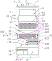
FIG. 2 is a schematic structural view of the cross section of the present invention;
fig. 3 is a schematic view of the cross-sectional structure of the side view of the present invention.
In the figure: 1. a treatment tank; 2. a switch; 3. a control device; 4. a feeding port cover plate; 5. a throwing plate; 6. a crushing mechanism; 7. a squeegee; 8. a crushing mechanism; 9. a material guide chute; 10. a compression mechanism; 11. a water collecting tank; 12. a drying mechanism; 13. a water collecting tank; 14. a limiting plate; 15. an activated carbon plate; 16. a material receiving box; 61. a crushing roller; 62. a first drive motor; 81. a crushing roller; 82. a crushing knife; 83. a second drive motor; 101. a collection basket; 102. an electric telescopic rod; 103. a compression plate; 104. a discharge port; 121. a drying oven; 122. a stirring paddle; 123. a third drive motor; 124. a flow-through tube; 125. a shunt tube; 126. a drying fan; 127. a material guide plate.
Detailed Description
The technical solutions in the embodiments of the present invention will be described clearly and completely with reference to the accompanying drawings in the embodiments of the present invention, and it is obvious that the described embodiments are only some embodiments of the present invention, not all embodiments.
Referring to fig. 1-3, the present invention provides an embodiment: a garbage processor comprises a processing box 1, a switch 2 is arranged on one side of the top end of the processing box 1, a control device 3 is arranged on the other side of the top end of the processing box 1, a throwing-in opening cover plate 4 and a throwing-in plate 5 are sequentially arranged at the rear end of the processing box 1 from top to bottom, a crushing mechanism 6 is arranged at the upper end of the inside of the processing box 1, a scraper 7 is fixedly connected to the inside of the processing box 1 below the crushing mechanism 6, a crushing mechanism 8 is arranged below the scraper 7, a guide chute 9 is fixedly connected to the inside of the processing box 1 below the crushing mechanism 8, a compression mechanism 10 is arranged below the guide chute 9, a water receiving tank 11 is fixedly connected to one side of the inside of the processing box 1 below the compression mechanism 10, a drying mechanism 12 is arranged on the other side of the inside of the processing box 1 below the compression mechanism 10, a water receiving tank 13 is arranged below the water receiving tank 11, a limiting plate 14 is fixedly connected inside the water receiving tank 13, an activated carbon plate 15 is arranged at the upper end of the limiting plate 14 inside the water receiving tank 13, and a material receiving tank 16 is arranged below the drying mechanism 12 inside the treatment tank 1.
Further, crushing mechanism 6 includes crushing roller 61, the one end transmission of crushing roller 61 is connected with the transmission end of first driving motor 62, and the both ends of crushing roller 61 are passed through the bearing with the inboard of handling case 1 and are rotated and be connected, first driving motor 62 and the outside fixed connection who handles case 1, and crushing roller 61 and the equal symmetry of first driving motor 62 are provided with two, the board 5 that puts in of the oblique top of crushing roller 61 adopts the slope structural design, scraper blade 7 is provided with two about the vertical central line symmetry of handling case 1, realize the preliminary crushing of solid in the rubbish.
Further, scraper blade 7 and two crushing roller 61 one-to-one, and the interval of scraping end and the crushing roller 61 of scraper blade 7 is less than 1cm, ensures to scrape the rubbish of adhesion on the crushing roller 61 down.
Further, the crushing mechanism 8 comprises a crushing roller 81, a layer of crushing knife 82 is fixedly connected to the surface of the crushing roller 81, two ends of the crushing roller 81 are rotatably connected with the inner side of the treatment box 1 through bearings, one end of the crushing roller 81 is connected with a transmission end of a second driving motor 83 in a transmission mode, the two crushing rollers 81 and the second driving motor 83 are symmetrically arranged, and the second driving motor 83 is fixedly connected with the outer side of the treatment box 1 to crush garbage.
Further, compressing mechanism 10 is including collecting basket 101, and the bilateral symmetry of collecting basket 101 is provided with two electric telescopic handle 102, and the upper end of collecting basket 101 is provided with the import, and electric telescopic handle 102's expansion end fixedly connected with compression plate 103, one side that collects basket 101 and be close to drying mechanism 12 are provided with discharge gate 104, realize the waste liquid extrusion in the rubbish.
Further, the drying mechanism 12 includes a drying box 121, the inside of the drying box 121 is rotatably connected with a stirring paddle 122, one end of the stirring paddle 122 extends to the outside of the processing box 1 and is connected with a third driving motor 123 in a transmission manner, the third driving motor 123 is connected with the outside of the processing box 1, the third driving motor 123 and the stirring paddle 122 are respectively and symmetrically arranged in two, the side of the drying box 121 is fixedly connected with a circulation pipe 124, one end of the circulation pipe 124 is fixedly connected with one side of a diversion pipe 125, the other side of the diversion pipe 125 is provided with an air outlet, the other end of the circulation pipe 124 is fixedly connected with a drying fan 126, the drying fan 126 is connected with the outside of the processing box 1, the drying fan 126, the diversion pipe 125 and the circulation pipe 124 are respectively and symmetrically arranged in two, the lower end of the drying box 121 is symmetrically and fixedly connected with two material guide plates 127 for, and drying the scattered garbage.
Further, the inside of the activated carbon plate 15 adopts a through hole structure design, so that the odor removal and the disinfection of the waste liquid are realized.
The working principle is as follows: the control device 3 is respectively electrically connected with the switch 2, the first driving motor 62, the second driving motor 83, the third driving motor 123 and the drying fan 126, when the garbage is treated, the garbage processor is started through the switch 2, the input opening cover plate 4 is pushed to input the garbage into the treatment box 1, the input plate 5 guides the garbage between the two crushing rollers 61, the first driving motor 62 drives the crushing rollers 61 to rotate, the crushing rollers 61 crush the garbage, the scraping plate 7 scrapes the garbage adhered on the crushing rollers 61, the garbage enters the crushing mechanism 8 from between the crushing rollers 61, the second driving motor 83 drives the crushing knife 82 on the surface of the crushing roller 81 to rotate, the crushing knife 82 crushes the garbage, the crushed garbage falls into the collection basket 101, the electric telescopic rod 102 close to one side of the drying mechanism 12 pushes the compression plate 103 to move, the two compression plates 103 compress the garbage, the waste liquid of extrusion falls into on the activated carbon board 15 in receiving water tank 13, remove the flavor disinfection to it by activated carbon board 15, then leave in the inside of receiving water tank 13, after the compression is accomplished, electric telescopic handle 102 who is close to drying mechanism 12 one side contracts, electric telescopic handle 102 who keeps away from drying mechanism 12 one side extends, the rubbish that will compress moves to discharge gate 104, two compression boards 103 loosen rubbish, under the effect of gravity, rubbish slowly falls out from discharge gate 104, third driving motor 123 drives stirring rake 122 and rotates, stirring rake 122 breaks up the rubbish of compression, drying fan 126 blows off hot-blastly simultaneously, discharge through the exhaust vent on shunt tubes 125, and then dry rubbish through the hot-blast hot-air that flows, the rubbish after the drying falls into receiving box 16, after a period, it can with rubbish to clear up the liquid in receiving water tank 13 and the receiving box 16.
It is obvious to a person skilled in the art that the invention is not restricted to details of the above-described exemplary embodiments, but that it can be implemented in other specific forms without departing from the spirit or essential characteristics of the invention. The present embodiments are therefore to be considered in all respects as illustrative and not restrictive, the scope of the invention being indicated by the appended claims rather than by the foregoing description, and all changes which come within the meaning and range of equivalency of the claims are therefore intended to be embraced therein. Any reference sign in a claim should not be construed as limiting the claim concerned.
Claims (7)
1. A waste processor comprising a processing tank (1), characterized in that: the device is characterized in that a switch (2) is arranged on one side of the top end of the treatment box (1), a control device (3) is arranged on the other side of the top end of the treatment box (1), a throwing-in port cover plate (4) and a throwing-in plate (5) are sequentially arranged at the rear end of the treatment box (1) from top to bottom, a crushing mechanism (6) is arranged at the upper end of the interior of the treatment box (1), a scraper plate (7) is fixedly connected to the lower portion of the crushing mechanism (6) in the interior of the treatment box (1), a crushing mechanism (8) is arranged below the scraper plate (7) in the interior of the treatment box (1), a guide chute (9) is fixedly connected to the lower portion of the crushing mechanism (8) in the interior of the treatment box (1), a compression mechanism (10) is arranged below the guide chute (9) in the interior of the treatment box (1), and a water receiving chute (11) is fixedly connected to one side of the, the opposite side that the inside of handling case (1) is located compressing mechanism (10) below is provided with drying mechanism (12), the below that the inside of handling case (1) is located water receiving tank (11) is provided with water receiving tank (13), the inside fixedly connected with limiting plate (14) of water receiving tank (13), the upper end that the inside of water receiving tank (13) is located limiting plate (14) is provided with activated carbon plate (15), the below that the inside of handling case (1) is located drying mechanism (12) is provided with material receiving tank (16).
2. A waste processor according to claim 1, wherein: crushing mechanism (6) are including crushing roller (61), the one end transmission of crushing roller (61) is connected with the transmission end of first driving motor (62), and the both ends of crushing roller (61) are passed through the bearing rotation with the inboard of handling case (1) and are connected, first driving motor (62) and the outside fixed connection who handles case (1), and crushing roller (61) and first driving motor (62) equal symmetry are provided with two, throwing board (5) above crushing roller (61) slope adopts slope structural design, scraper blade (7) are provided with two about the vertical central line symmetry of handling case (1).
3. A waste processor according to claim 2, wherein: the scraping plates (7) are in one-to-one correspondence with the two crushing rollers (61), and the distance between the scraping ends of the scraping plates (7) and the crushing rollers (61) is smaller than 1 cm.
4. A waste processor according to claim 1, wherein: rubbing crusher constructs (8) including smashing roller (81), the fixed surface of smashing roller (81) is connected with one deck and smashes sword (82), and the both ends of smashing roller (81) and the inboard of handling case (1) are passed through the bearing and are rotated and be connected, the one end transmission of smashing roller (81) is connected with the transmission end of second driving motor (83), and smashes roller (81) and second driving motor (83) symmetry respectively and is provided with two, second driving motor (83) and the outside fixed connection who handles case (1).
5. A waste processor according to claim 1, wherein: compressing mechanism (10) is including collecting basket (101), the bilateral symmetry of collecting basket (101) is provided with two electric telescopic handle (102), and the upper end of collecting basket (101) is provided with the import, the expansion end fixedly connected with compression board (103) of electric telescopic handle (102), one side that collection basket (101) is close to drying mechanism (12) is provided with discharge gate (104).
6. A waste processor according to claim 1, wherein: drying mechanism (12) is including drying cabinet (121), the inside of drying cabinet (121) is rotated and is connected with stirring rake (122), the outside transmission that the one end of stirring rake (122) extends to handling case (1) is connected with third driving motor (123), third driving motor (123) and the outside interconnect of handling case (1), and third driving motor (123) and stirring rake (122) symmetry respectively are provided with two, the avris fixedly connected with flow tube (124) of drying cabinet (121), one side of the one end fixedly connected with shunt tubes (125) of flow tube (124), the opposite side of shunt tubes (125) is provided with the exhaust vent, the other end fixedly connected with drying blower (126) of flow tube (124), drying blower (126) and the outside interconnect of handling case (1), and drying blower (126), The two diversion pipes (125) and the two circulation pipes (124) are respectively and symmetrically arranged, and the lower end of the drying box (121) is symmetrically and fixedly connected with two material guide plates (127).
7. A waste processor according to claim 1, wherein: the interior of the active carbon plate (15) adopts a through hole structure design.
Priority Applications (1)
| Application Number | Priority Date | Filing Date | Title |
|---|---|---|---|
| CN201921890842.3U CN211026491U (en) | 2019-11-05 | 2019-11-05 | Garbage processor |
Applications Claiming Priority (1)
| Application Number | Priority Date | Filing Date | Title |
|---|---|---|---|
| CN201921890842.3U CN211026491U (en) | 2019-11-05 | 2019-11-05 | Garbage processor |
Publications (1)
| Publication Number | Publication Date |
|---|---|
| CN211026491U true CN211026491U (en) | 2020-07-17 |
Family
ID=71545173
Family Applications (1)
| Application Number | Title | Priority Date | Filing Date |
|---|---|---|---|
| CN201921890842.3U Active CN211026491U (en) | 2019-11-05 | 2019-11-05 | Garbage processor |
Country Status (1)
| Country | Link |
|---|---|
| CN (1) | CN211026491U (en) |
Cited By (4)
| Publication number | Priority date | Publication date | Assignee | Title |
|---|---|---|---|---|
| CN111906122A (en) * | 2020-08-10 | 2020-11-10 | 环亮环境科技有限公司 | Household garbage classification treatment and regeneration device |
| CN112123838A (en) * | 2020-08-12 | 2020-12-25 | 孙增光 | Transmission system and host computer integral type meat sediment compression equipment for leather processing |
| CN112517203A (en) * | 2020-11-12 | 2021-03-19 | 淮北辰威科技有限公司 | Garbage disposal device |
| WO2022062229A1 (en) * | 2020-09-23 | 2022-03-31 | 淄博创立机电科技有限公司 | Environment-friendly restaurant food waste cleaning apparatus |
-
2019
- 2019-11-05 CN CN201921890842.3U patent/CN211026491U/en active Active
Cited By (5)
| Publication number | Priority date | Publication date | Assignee | Title |
|---|---|---|---|---|
| CN111906122A (en) * | 2020-08-10 | 2020-11-10 | 环亮环境科技有限公司 | Household garbage classification treatment and regeneration device |
| CN111906122B (en) * | 2020-08-10 | 2023-05-26 | 环亮环境科技有限公司 | Household garbage classification treatment and regeneration device |
| CN112123838A (en) * | 2020-08-12 | 2020-12-25 | 孙增光 | Transmission system and host computer integral type meat sediment compression equipment for leather processing |
| WO2022062229A1 (en) * | 2020-09-23 | 2022-03-31 | 淄博创立机电科技有限公司 | Environment-friendly restaurant food waste cleaning apparatus |
| CN112517203A (en) * | 2020-11-12 | 2021-03-19 | 淮北辰威科技有限公司 | Garbage disposal device |
Similar Documents
| Publication | Publication Date | Title |
|---|---|---|
| CN211026491U (en) | Garbage processor | |
| KR20100041989A (en) | Apparatus for refuse and waste water treatment | |
| CN214348569U (en) | Kitchen waste treatment device | |
| CN212733522U (en) | Integrated kitchen waste treatment device | |
| CN216726056U (en) | High-efficient cleaning device of sewage treatment pond solid waste | |
| CN208912786U (en) | A kind of building castoff collection centralized processor | |
| CN214765729U (en) | Kitchen garbage is reducing mechanism for processing | |
| CN107998688B (en) | Catering industry sewage filter equipment | |
| CN112371254B (en) | Dewatering, crushing and drying method for food waste | |
| CN210753061U (en) | Kitchen waste pretreatment equipment | |
| CN112403626A (en) | Dehydration and crushing device for kitchen waste treatment and using method thereof | |
| CN218656074U (en) | Recovery unit is smashed to solid organic waste | |
| CN216936202U (en) | Garbage crushing treatment device for environmental protection | |
| CN215696708U (en) | A refuse treatment device for hydraulic engineering uses | |
| CN215551143U (en) | Domestic kitchen garbage treatment equipment | |
| CN112277363B (en) | High-efficient kitchen garbage processing system | |
| CN212147653U (en) | Kitchen garbage swill treatment facility | |
| CN211887067U (en) | Traditional chinese medicine is dried and is smashed all-in-one | |
| CN211678077U (en) | A processing apparatus for kitchen garbage | |
| CN211251435U (en) | Kitchen waste treatment device | |
| CN210302660U (en) | Difficult surplus rubbish automatic slag removal device of meal of jam | |
| CN108468364B (en) | Kitchen wastewater treatment device and use method thereof | |
| CN112044931A (en) | Recovery plant for crushing and compressing urban living dry garbage | |
| CN218778233U (en) | Fish viscera retrieves conveyer | |
| CN217190007U (en) | Domestic garbage treatment device |
Legal Events
| Date | Code | Title | Description |
|---|---|---|---|
| GR01 | Patent grant | ||
| GR01 | Patent grant |