CN210914369U - Glass conveying and positioning device - Google Patents
Glass conveying and positioning device Download PDFInfo
- Publication number
- CN210914369U CN210914369U CN201921389544.6U CN201921389544U CN210914369U CN 210914369 U CN210914369 U CN 210914369U CN 201921389544 U CN201921389544 U CN 201921389544U CN 210914369 U CN210914369 U CN 210914369U
- Authority
- CN
- China
- Prior art keywords
- frame
- positioning
- fixed
- wheel
- lifting
- Prior art date
- Legal status (The legal status is an assumption and is not a legal conclusion. Google has not performed a legal analysis and makes no representation as to the accuracy of the status listed.)
- Active
Links
Images


Abstract
The utility model discloses a glass conveying and positioning device, which comprises a frame body, a lifting frame, a conveying belt assembly, a left supporting frame, a left positioning wheel, a right supporting frame, a right positioning wheel, a front positioning frame, a front positioning cylinder, a front positioning wheel, a rear positioning cylinder, a rear positioning wheel and a rear positioning frame, wherein the lifting frame is fixed in the frame body; a conveyor belt assembly is fixed at the upper end of the lifting frame, and a left support frame and a right support frame are respectively arranged on two sides of the conveyor belt assembly; the left positioning wheel is fixed on the left supporting frame, the right positioning wheel is fixed on the right supporting frame, the front side of the conveyor belt assembly is provided with a front positioning frame fixed on the lifting frame, the front positioning frame is connected with the front positioning wheel through a shaft, the rear side of the conveyor belt assembly is provided with a rear positioning frame fixed on the lifting frame, and the rear positioning frame is connected with the rear positioning wheel through a shaft. The cost is reduced, and the efficiency is improved; the application range is wide, the use requirement is met, the conveying and positioning accuracy is high, and the product quality is favorably improved.
Description
Technical Field
The utility model relates to a photovoltaic equipment technical field, concretely relates to a panel glass's conveying positioner for automatic welding machine converges.
Background
In recent years, with the development of the solar power generation industry, some automatic processing equipment for solar panels appears on the market.
When solar panels are produced, various glass conveying mechanisms are required. Most of common glass conveying mechanisms can only convey and turn, and the use requirements cannot be met at a battery string welding station. Manual operation is required. The efficiency is low, the labor is increased, and the cost is wasted; meanwhile, the manual operation stability is poor, the positioning precision is low, and the product quality is influenced.
SUMMERY OF THE UTILITY MODEL
The utility model aims to provide a glass conveying and positioning device, which overcomes the defects of the prior art, has simple and reasonable structural design, automatic transmission, no need of manpower, reduced cost and improved efficiency; the lifting positioning device has the advantages of lifting and positioning functions, wide application range, high transmission and positioning precision, capability of meeting the use requirements, contribution to improving the product quality and convenience in popularization of products.
In order to achieve the above design purpose, the utility model discloses a technical scheme as follows:
a glass conveying and positioning device comprises a frame body, a lifting frame, a conveying belt assembly, a lifting motor, a lifting chain, a lifting guide rail, a left supporting frame, a left positioning wheel, a right supporting frame, a right positioning wheel, a front positioning frame, a front positioning cylinder, a front positioning wheel, a rear positioning cylinder, a rear positioning wheel and a rear positioning frame, wherein the lifting guide rail is arranged on each of two sides of the frame body; a conveyor belt assembly is fixed at the upper end of the lifting frame, a left support frame fixed on the lifting frame is arranged on the left side of the conveyor belt assembly, and a right support frame fixed on the lifting frame is arranged on the right side of the conveyor belt assembly; the utility model discloses a glass positioning device, including left side support frame, right side support frame, locating wheel, conveyer belt subassembly front side, fixed left locating wheel, fixed right locating wheel on the left side support frame, left side locating wheel, right locating wheel are used for fixing a position glass left and right ends, conveyer belt subassembly front side is equipped with the preceding locating rack of fixing on the crane, through the fixed preceding location cylinder of preceding location cylinder support frame on the preceding locating rack, locating wheel before the terminal coupling of piston rod of preceding location cylinder, conveyer belt subassembly rear side is equipped with the back locating rack of fixing on the crane, fixes back location cylinder on the back locating rack, and the terminal coupling back locating wheel of piston rod of back location cylinder, preceding locating wheel, back locating wheel are used.
And the front positioning cylinder and the rear positioning cylinder both adopt rotary clamping cylinders.
A left positioning air cylinder is fixed on the left supporting frame, the tail end of a piston rod of the left positioning air cylinder is connected with a left positioning wheel in a shaft mode, a right positioning wheel frame is fixed on the right supporting frame, and a right positioning wheel is fixed on the right positioning wheel frame.
The left support frame downside is fixed on the left support chassis through left support guide rail slidable, and the left support chassis is fixed on the crane, and the right support frame downside is fixed on the right support chassis through guide rail slidable, and the right support chassis is fixed on the crane.
The lower side of the left supporting underframe is locked with a left supporting motor, the output end of the left supporting motor is synchronously connected to a left supporting lead screw component, the left supporting lead screw component is fixed on the lower side of the left supporting underframe through a left supporting lead screw frame, and a nut of the left supporting lead screw component is synchronously connected to a left supporting frame; the relative movement of the right supporting underframe and the right supporting frame and the relative movement of the left supporting underframe and the left supporting frame adopt the same structure.
The glass supporting frame is characterized in that a left supporting plate is arranged on the left supporting frame, a right supporting plate is arranged on the right supporting frame, an inclined plane is arranged on one side, close to the glass, of the left supporting plate, and an inclined plane is arranged on one side, close to the glass, of the right supporting plate.
The lower side of the front positioning frame movably fixes a front positioning underframe through a front positioning guide rail, and the front positioning underframe is fixed on the lifting frame; a front positioning motor is fixed on the lower side of the front positioning underframe, the output end of the front positioning motor is synchronously connected to a front positioning screw rod assembly, and a nut of the front positioning screw rod assembly is synchronously connected to a front positioning frame; the lower side of the rear positioning frame is movably fixed with a rear positioning underframe through a rear positioning guide rail, and the rear positioning underframe is fixed on the lifting frame; the rear positioning motor is fixed on the lower side of the rear positioning underframe, the output end of the rear positioning motor is synchronously connected to the rear positioning screw rod assembly, and the nut of the rear positioning screw rod assembly is synchronously connected to the rear positioning frame.
The output end of the lifting motor is synchronously connected to a lifting synchronizing rod through a speed reducer, the lifting synchronizing rod is connected to the top end of the frame body through a bearing assembly in a shaft mode, the lifting synchronizing rod is close to two ends and is respectively connected with a lifting chain in a synchronous mode, the bottom end of the frame body is connected with a lower chain wheel through a lower chain wheel fixing seat in a shaft mode, the lower chain wheel is connected to the lifting chain, and the lifting chain is synchronously connected to the lifting frame through a.
The conveyer belt subassembly includes two at least conveyer belts that set up side by side, and the conveyer belt both ends are fixed at conveyer belt frame both ends through the synchronizing wheel respectively, and the synchronizing wheel synchro coupling of conveyer belt frame one end is to conveyer belt drive synchronizing bar, and conveyer belt drive synchronizing bar synchro coupling is to the conveyer belt motor.
And the front positioning frame is also fixed with an inductor.
Glass conveying positioner beneficial effect be: the structure design is simple and reasonable, automatic transmission is realized, no manual work is needed, the cost is reduced, and the efficiency is improved; the lifting positioning device has the advantages of lifting and positioning functions, wide application range, high transmission and positioning precision, capability of meeting the use requirements, contribution to improving the product quality and convenience in popularization of products.
Drawings
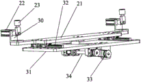
FIG. 1 is a perspective view of a glass transfer positioning apparatus according to the present invention;
FIG. 2 is a perspective view of another angle of the glass transfer positioning apparatus of the present invention;
FIG. 3 is a top view of the glass transfer positioning apparatus of the present invention;
FIG. 4 is a perspective view of the front positioning mechanism of the glass conveying and positioning device of the present invention;
FIG. 5 is a perspective view of another angle of the front positioning mechanism of the glass transfer positioning apparatus of the present invention;
FIG. 6 is a perspective view of the left positioning mechanism of the glass conveying and positioning device of the present invention;
fig. 7 is a perspective view of another angle of the left positioning mechanism of the glass conveying and positioning device of the present invention.
Detailed Description
The technical solution in the embodiments of the present invention will be clearly and completely described below with reference to the accompanying drawings in the embodiments of the present invention.
The concrete structure is shown in figures 1-7, the glass conveying and positioning device comprises a frame body 1, a lifting frame 2, a conveyor belt component 3, a lifting motor 5, a lifting chain 7, a lifting guide rail 8, a left support frame 11, a left positioning wheel 14, a right support frame 16, a right positioning wheel 18, a front positioning frame 21, a front positioning cylinder 22, a front positioning wheel 23, a rear positioning cylinder 24, a rear positioning wheel 25 and a rear positioning frame 26, two sides of the frame body 1 are respectively provided with a lifting guide rail 8, two ends of the lifting frame 2 are respectively fixed on the lifting guide rails 8 through slide blocks, the two ends of the lifting frame 2 are respectively connected to a lifting chain 7, the lifting chain 7 is synchronously connected to a lifting motor 5, the lifting motor 5 is fixed at the top end of the frame body 1, the lifting motor 5 drives the lifting chain 7, and the lifting frame 2 is driven by the lifting chain 7 to lift on the lifting guide rail 8 so as to meet the conveying requirements of different heights of the glass; the conveyor belt component 3 is fixed at the upper end of the lifting frame 2 and used for conveying glass, a left support frame 11 fixed on the lifting frame 2 is arranged on the left side of the conveyor belt component 3, a right support frame 16 fixed on the lifting frame 2 is arranged on the right side of the conveyor belt component 3, the left support frame 11 and the right support frame 16 are used for supporting large-size glass, when the conveyor belt component is applied to conveying small-size glass, the left end and the right end of the small-size glass are respectively supported on the conveyor belt component 3, when the conveyor belt component is applied to conveying large-size glass, the left end and the right end of the large-size glass are respectively supported on the left support frame 11 and the right support frame 16, and the problem that; the fixed left positioning wheel 14 on the left branch strut 11, the fixed right positioning wheel 18 on the right branch strut 16, left positioning wheel 14, right positioning wheel 18 are used for fixing a position glass left and right ends, 3 front sides of conveyer belt subassembly are equipped with fixes preceding locating rack 21 on crane 2, fix preceding location cylinder 22 through preceding location cylinder support frame 30 on preceding locating rack 21, and locating wheel 23 before the piston rod end coupling of preceding location cylinder 22, 3 rear sides of conveyer belt subassembly are equipped with fixes back locating rack 26 on crane 2, fixes back location cylinder 24 on the back locating rack 26, and back location cylinder 24's piston rod end coupling back positioning wheel 25, and preceding positioning wheel 23, back positioning wheel 25 are used for fixing a position the glass front and back end.
The front positioning cylinder 22 and the rear positioning cylinder 24 both adopt rotary clamping cylinders, when the glass positioning device is used, a front positioning wheel (rear positioning wheel) fixed at the tail end of a piston rod of each rotary clamping cylinder is horizontally arranged (lower than the bottom surface of glass), so that the influence on glass conveying is avoided, when the positioning is needed, the tail end of the piston rod of each rotary clamping cylinder rotates 90 degrees, so that the front positioning wheel (rear positioning wheel) is vertically arranged (higher than the top surface of the glass), and then the piston rod of each rotary clamping cylinder stretches out and draws back to position the glass; after the location is accomplished, when needing to leave the glass conveying, the piston rod of gyration die clamping cylinder is flexible for the terminal preceding locating wheel of piston rod (back locating wheel) leaves glass, then gyration die clamping cylinder's piston rod is rotatory 90 degrees, makes preceding locating wheel (back locating wheel) be in horizontal position, then leave the glass conveying can.
When the glass conveying belt component is used, after glass enters the conveying belt component 3, the left positioning cylinder 13 is started to push the glass to be clamped between the left positioning wheel 14 and the right positioning wheel 18.
The lower side of the left support frame 11 is fixed on the left support chassis 15 in a slidable manner through the left support guide rail 35, the left support chassis 15 is fixed on the lifting frame 2, the lower side of the right support frame 16 is fixed on the right support chassis 20 in a slidable manner through the guide rail, the right support chassis 20 is fixed on the lifting frame 2, the left support frame 11 can move on the left support chassis 15, the right support frame 16 can move on the right support chassis 20, the left end and the right end of glass are clamped, and the glass with different width specifications can be applied.
The left side supports 15 downside and passes through screw lock and connect left support motor 37, left support motor 37's output synchronous connection to left support lead screw subassembly 38, left support lead screw subassembly 38 is fixed at left support chassis 15 downside through left support lead screw frame 36, the screw synchronous connection of left support lead screw subassembly 38 to left support frame 11, drive left support lead screw subassembly 38 through left support motor 37 and move, drive left support frame 11 through the screw of left support lead screw subassembly 38 and remove, during the use, glass enters into behind the conveyer belt subassembly 3, left support frame 11 removes, make the glass left end support on left support frame 11, and fix a position through left positioning wheel 14 on the left support frame 11. The relative movement of the right supporting underframe 20 and the right supporting underframe 16 and the relative movement of the left supporting underframe 15 and the left supporting underframe 11 adopt the same structure.
Be equipped with left branch fagging 12 on the left branch fagging 11 for support the glass left end, be equipped with right branch fagging 19 on the right branch fagging 16 for support the glass right-hand member, one side that left branch fagging 12 is close to glass is equipped with inclined plane 20, and one side that right branch fagging 19 is close to glass is equipped with inclined plane 20, makes things convenient for the glass both ends to reach on left branch fagging 12, the right branch fagging.
The lower side of the front positioning frame 21 is movably fixed with a front positioning underframe 31 through a front positioning guide rail 32, the front positioning underframe 31 is fixed on the lifting frame 2, and the front positioning frame 21 can move on the front positioning underframe 31 to realize the front end positioning of the glass; a front positioning motor 33 is fixed on the lower side of the front positioning underframe 31, the output end of the front positioning motor 33 is synchronously connected to a front positioning screw rod assembly 34, a nut of the front positioning screw rod assembly 34 is synchronously connected to the front positioning frame 21, the front positioning screw rod assembly 34 is driven by the front positioning motor 33 to move, and then the front positioning frame 21 is driven to move on the front positioning underframe 31, so that the front end of the glass is positioned; the lower side of the rear positioning frame 26 is movably fixed with a rear positioning underframe through a rear positioning guide rail, and the rear positioning underframe is fixed on the lifting frame; the rear positioning motor is fixed on the lower side of the rear positioning underframe, the output end of the rear positioning motor is synchronously connected to the rear positioning screw rod assembly, the nut of the rear positioning screw rod assembly is synchronously connected to the rear positioning frame, the lifting frame 2 is moved, and the rear end of the glass is positioned.
The output of elevator motor 5 passes through speed reducer synchronous connection to lift synchronizing bar 6, and lift synchronizing bar 6 passes through the bearing subassembly coupling on 1 top of support body, and lift synchronizing bar 6 is close to both ends punishment and do not the synchronous connection lift chain 7, 1 bottom of support body is through lower sprocket fixing base 10 coupling lower sprocket 9, and lower sprocket 9 is connected to lift chain 7, lift chain 7 is through 4 synchronous connections of chain fixed plate to crane 2, drives the lift chain 7 rotation of both sides through lift synchronizing bar 6, drives crane 2 through chain fixed plate 4 and goes up and down.
The conveyor belt component 3 comprises at least two conveyor belts arranged side by side, the two ends of each conveyor belt are fixed at the two ends of a conveyor belt frame through synchronizing wheels respectively, the synchronizing wheels at one end of each conveyor belt frame are synchronously connected to a conveyor belt driving synchronizing rod 29, the conveyor belt driving synchronizing rods 29 are synchronously connected to a conveyor belt motor 28, the conveyor belt driving synchronizing rods 29 are driven by the conveyor belt motor 28 to synchronously rotate, the synchronizing wheels are driven by the conveyor belt driving synchronizing rods 29 to synchronously rotate, and the conveyor belts are driven by the synchronizing wheels to synchronously rotate.
The front positioning frame 21 is also fixed with a sensor 27 for sensing whether glass exists on the conveyor belt assembly 3 or not for the next operation.
The foregoing is a more detailed description of the invention, taken in conjunction with the specific preferred embodiments thereof, so that those skilled in the art can readily understand and apply the invention, and it is not intended to limit the invention to the specific embodiments described. To the ordinary technical personnel in the technical field that the utility model belongs to, can also make a plurality of simple deductions or replacement under the prerequisite that does not deviate from the utility model discloses the design, and needn't pass through creative work. Therefore, the simple modifications made by those skilled in the art according to the disclosure of the present invention should be within the scope of the present invention.
Claims (9)
1. The utility model provides a glass conveying positioner which characterized in that: the lifting mechanism comprises a frame body, a lifting frame, a conveyor belt assembly, a lifting motor, a lifting chain, a lifting guide rail, a left supporting frame, a left positioning wheel, a right supporting frame, a right positioning wheel, a front positioning frame, a front positioning cylinder, a front positioning wheel, a rear positioning cylinder, a rear positioning wheel and a rear positioning frame, wherein the lifting guide rail is arranged on each of two sides of the frame body; a conveyor belt assembly is fixed at the upper end of the lifting frame, a left support frame fixed on the lifting frame is arranged on the left side of the conveyor belt assembly, and a right support frame fixed on the lifting frame is arranged on the right side of the conveyor belt assembly; the utility model discloses a glass positioning device, including left side support frame, right side support frame, locating wheel, conveyer belt subassembly front side, fixed left locating wheel, fixed right locating wheel on the left side support frame, left side locating wheel, right locating wheel are used for fixing a position glass left and right ends, conveyer belt subassembly front side is equipped with the preceding locating rack of fixing on the crane, through the fixed preceding location cylinder of preceding location cylinder support frame on the preceding locating rack, locating wheel before the terminal coupling of piston rod of preceding location cylinder, conveyer belt subassembly rear side is equipped with the back locating rack of fixing on the crane, fixes back location cylinder on the back locating rack, and the terminal coupling back locating wheel of piston rod of back location cylinder, preceding locating wheel, back locating wheel are used.
2. The glass transfer positioning apparatus of claim 1, wherein: and the front positioning cylinder and the rear positioning cylinder both adopt rotary clamping cylinders.
3. The glass transfer positioning apparatus of claim 1, wherein: a left positioning air cylinder is fixed on the left supporting frame, the tail end of a piston rod of the left positioning air cylinder is connected with a left positioning wheel in a shaft mode, a right positioning wheel frame is fixed on the right supporting frame, and a right positioning wheel is fixed on the right positioning wheel frame.
4. The glass transfer positioning apparatus of claim 1, wherein: the left support frame downside is fixed on the left support chassis through left support guide rail slidable, and the left support chassis is fixed on the crane, and the right support frame downside is fixed on the right support chassis through guide rail slidable, and the right support chassis is fixed on the crane.
5. The glass transfer positioning apparatus of claim 4, wherein: the lower side of the left supporting underframe is locked with a left supporting motor, the output end of the left supporting motor is synchronously connected to a left supporting lead screw component, the left supporting lead screw component is fixed on the lower side of the left supporting underframe through a left supporting lead screw frame, and a nut of the left supporting lead screw component is synchronously connected to a left supporting frame; the relative movement of the right supporting underframe and the right supporting frame and the relative movement of the left supporting underframe and the left supporting frame adopt the same structure.
6. The glass transfer positioning apparatus of claim 5, wherein: the glass supporting frame is characterized in that a left supporting plate is arranged on the left supporting frame, a right supporting plate is arranged on the right supporting frame, an inclined plane is arranged on one side, close to the glass, of the left supporting plate, and an inclined plane is arranged on one side, close to the glass, of the right supporting plate.
7. The glass transfer positioning apparatus of claim 1, wherein: the lower side of the front positioning frame movably fixes a front positioning underframe through a front positioning guide rail, and the front positioning underframe is fixed on the lifting frame; a front positioning motor is fixed on the lower side of the front positioning underframe, the output end of the front positioning motor is synchronously connected to a front positioning screw rod assembly, and a nut of the front positioning screw rod assembly is synchronously connected to a front positioning frame; the lower side of the rear positioning frame is movably fixed with a rear positioning underframe through a rear positioning guide rail, and the rear positioning underframe is fixed on the lifting frame; the rear positioning motor is fixed on the lower side of the rear positioning underframe, the output end of the rear positioning motor is synchronously connected to the rear positioning screw rod assembly, and the nut of the rear positioning screw rod assembly is synchronously connected to the rear positioning frame.
8. The glass transfer positioning apparatus of claim 1, wherein: the output end of the lifting motor is synchronously connected to a lifting synchronizing rod through a speed reducer, the lifting synchronizing rod is connected to the top end of the frame body through a bearing assembly in a shaft mode, the lifting synchronizing rod is close to two ends and is respectively connected with a lifting chain in a synchronous mode, the bottom end of the frame body is connected with a lower chain wheel through a lower chain wheel fixing seat in a shaft mode, the lower chain wheel is connected to the lifting chain, and the lifting chain is synchronously connected to the lifting frame through a.
9. The glass transfer positioning apparatus of claim 1, wherein: the conveyer belt subassembly includes two at least conveyer belts that set up side by side, and the conveyer belt both ends are fixed at conveyer belt frame both ends through the synchronizing wheel respectively, and the synchronizing wheel synchro coupling of conveyer belt frame one end is to conveyer belt drive synchronizing bar, and conveyer belt drive synchronizing bar synchro coupling is to the conveyer belt motor.
Priority Applications (1)
| Application Number | Priority Date | Filing Date | Title |
|---|---|---|---|
| CN201921389544.6U CN210914369U (en) | 2019-08-23 | 2019-08-23 | Glass conveying and positioning device |
Applications Claiming Priority (1)
| Application Number | Priority Date | Filing Date | Title |
|---|---|---|---|
| CN201921389544.6U CN210914369U (en) | 2019-08-23 | 2019-08-23 | Glass conveying and positioning device |
Publications (1)
| Publication Number | Publication Date |
|---|---|
| CN210914369U true CN210914369U (en) | 2020-07-03 |
Family
ID=71361842
Family Applications (1)
| Application Number | Title | Priority Date | Filing Date |
|---|---|---|---|
| CN201921389544.6U Active CN210914369U (en) | 2019-08-23 | 2019-08-23 | Glass conveying and positioning device |
Country Status (1)
| Country | Link |
|---|---|
| CN (1) | CN210914369U (en) |
-
2019
- 2019-08-23 CN CN201921389544.6U patent/CN210914369U/en active Active
Similar Documents
| Publication | Publication Date | Title |
|---|---|---|
| CN201545661U (en) | Track-hoist lifter for lifting objects through chassis line | |
| CN202499548U (en) | Automatic loading and unloading system | |
| CN201900410U (en) | Automatic welding device | |
| CN203150530U (en) | Transporting and screening device for battery packs | |
| CN212587399U (en) | Keyboard backlight plate assembly equipment | |
| CN112374143A (en) | Cleaning and loading mechanism for solar panel | |
| CN210914369U (en) | Glass conveying and positioning device | |
| CN219227970U (en) | Crawler-type panel turnover machine for circuit board | |
| CN210703509U (en) | Automatic assembling equipment for water pump core | |
| CN212019954U (en) | Socket material loading lock screw machine | |
| CN213170287U (en) | Automatic feeding module suitable for installation of solar aluminum alloy frame corner connectors | |
| CN110181205B (en) | Steel reinforcement framework sheet welding production line | |
| CN211210370U (en) | Paster device for surface mounting device | |
| CN210188873U (en) | Welding production line | |
| CN209242105U (en) | A kind of conveying device of automobile roof liner automatic assembly line | |
| CN210794731U (en) | Double-deck conveying equipment | |
| CN210937815U (en) | Full-automatic bus bar welding machine | |
| CN108811482B (en) | Multi-station hanging plug-in machine | |
| CN216928610U (en) | Automatic upset detects machine | |
| CN112739195A (en) | Intelligent manufacturing equipment for power circuit board | |
| CN113555465B (en) | Automatic corner penetrating and stacking device for photovoltaic frame | |
| CN220596923U (en) | Lifting base mechanism for conveying raw material bin | |
| CN219945519U (en) | Acrylic plate processing grinding device | |
| CN215114774U (en) | Automatic detection device for gas meter | |
| CN220164974U (en) | Transfer device and transformer transfer trolley |
Legal Events
| Date | Code | Title | Description |
|---|---|---|---|
| GR01 | Patent grant | ||
| GR01 | Patent grant |