CN210879782U - Denitration catalyst cutting mechanism - Google Patents
Denitration catalyst cutting mechanism Download PDFInfo
- Publication number
- CN210879782U CN210879782U CN201921609507.1U CN201921609507U CN210879782U CN 210879782 U CN210879782 U CN 210879782U CN 201921609507 U CN201921609507 U CN 201921609507U CN 210879782 U CN210879782 U CN 210879782U
- Authority
- CN
- China
- Prior art keywords
- transfer
- rod
- denitration catalyst
- station
- cutter
- Prior art date
- Legal status (The legal status is an assumption and is not a legal conclusion. Google has not performed a legal analysis and makes no representation as to the accuracy of the status listed.)
- Active
Links
Images


Abstract
The utility model discloses a denitration catalyst cutting mechanism, which comprises a knife rest arranged in a mirror image manner, a transfer mechanism, a first conveying belt and a second conveying belt which are arranged on two sides of the knife rest; the tool rest is provided with a feeding mechanism, and the limit positions of the two ends of the feeding mechanism are a first station and a second station; a cutter is arranged on the cutter rest, and the direction of the cutter is intersected with the feeding direction; transport mechanism includes base, first transport pole, second transport pole, and first transport pole rotates to be connected on the base, and the second transports the pole and rotates to be connected on the base, and first transport pole pivoted extreme position is for waiting to get material department and first station department of cutting the piece, and second transport pole pivoted extreme position is off-the-shelf ejection of compact department and second station department, and blow mechanism sets up in the both sides of waiting to cut the piece and blows to and wait to cut a parallel. The utility model has the advantages that: the manual operation is not needed, the mechanical production is realized, the efficiency is high, and the safety index is high.
Description
Technical Field
The utility model relates to a cutting mechanism especially relates to a denitration catalyst cutting mechanism.
Background
The main raw material of the honeycomb catalyst is titanium oxide TiO (commonly known as titanium dioxide), and related additives are added, wherein the cross section is generally 150 × 150mm, the length is about 1000mm to 1500mm, and honeycomb holes are generally square (with different numbers of holes);
the production process of the honeycomb denitration catalyst mainly comprises the following steps: 1) preparing a formula; 2) stirring the raw materials uniformly at a high speed; 3) fully filtering the wet material by using a pre-filtering extruder; 4) putting the filtered raw materials into a vacuum extruder to carry out extrusion molding on the product; 5) the automatic synchronous cutting machine can cut the extruded blank according to different size requirements; 6) the extruded product is placed into a carton by a manipulator, so that the extruded product is not deformed; 7) primary drying; 8) Secondary drying; 9) firing in a mesh belt kiln; 10) cutting to length; 11) and (6) inspecting and packaging.
Strip-shaped or plate-shaped blank bodies are firstly segmented after being extruded from a die by the extruding equipment of the denitration catalyst, and in the segmenting process, because the catalyst just extruded is soft and the two ends are easy to deform, the problem of hole plugging is easy to exist for the honeycomb-shaped denitration catalyst, so that finished products need to be cut to length for the segmented blank bodies, and the uniformity is guaranteed.
The cutting mechanism of current cutting is after the cutting, mostly places in cutting equipment department for the manual work, and the finished product is transported by the manual work again after the cutting is accomplished, and inefficiency, safety index are low, and the leftover bits that cut do not have collection device yet, and the production site is mixed and disorderly, and is easy to pollute, is unfavorable for the recovery and recycles.
As in application No.: 201821921527.8 discloses a honeycomb catalyst cutting device, which belongs to the technical field of honeycomb catalyst production equipment. The device comprises a conveying mechanism, an equipment frame, an end face cutting device, a laser ranging mechanism and a waste material bearing mechanism, wherein the conveying mechanism comprises a supporting frame, a roller body, a conveying belt, a motor and a plurality of limiting parts; the equipment frame is arranged on one side of the conveying mechanism or arranged across the width direction of the conveying mechanism; an end face cutting device and a laser ranging mechanism are fixed on the equipment frame, a cutting part of the end face cutting device is arranged at one side close to the conveying belt, and the laser ranging mechanism respectively irradiates a specific position at two sides of the conveying belt; the waste material supporting mechanism is arranged right below the end face cutting device and comprises a hand-push flat car and a waste material supporting barrel placed on the hand-push flat car. Through setting up laser distance sensor, monitor the position of honeycomb catalyst, when deviating from the settlement position, can send alarm signal, guide operating personnel to adjust. This scheme detects the position through the sensor, realizes the scaling-off cutting, still needs the manual work to put into transport mechanism with each piece of waiting to cut, increases intensity of labour.
The information disclosed in this background section is only for enhancement of understanding of the general background of the invention and should not be taken as an acknowledgement or any form of suggestion that this information constitutes prior art already known to a person skilled in the art.
SUMMERY OF THE UTILITY MODEL
The utility model discloses the technical problem that will solve lies in: how to solve the problem of current denitration catalyst cutting device inefficiency.
The utility model discloses a following technical means realizes solving above-mentioned technical problem: the denitration catalyst cutting mechanism comprises tool rests arranged in a mirror image mode and a transfer mechanism arranged between the tool rests;
the tool rest is provided with a feeding mechanism capable of reciprocating, the limit positions of the two ends of the feeding mechanism are a first station and a second station, when in cutting, a piece to be cut is placed on the feeding mechanism, and the piece to be cut moves from the first station to the second station; a cutter is arranged on the cutter rest, and the direction of the cutter is intersected with the feeding direction;
the transferring mechanism comprises a base capable of moving up and down, a first transferring rod and a second transferring rod, the first transferring rod is rotatably connected to the base, the second transferring rod is rotatably connected to the base, the rotating limit positions of the first transferring rod are a material taking position and a first station position of a piece to be cut, and the rotating limit positions of the second transferring rod are a finished product discharging position and a second station position;
the cutting machine also comprises a first conveying belt for conveying the workpiece to be cut and a second conveying belt for conveying a finished product, wherein the first conveying belt and the second conveying belt are respectively arranged at two sides of the cutting mechanism, one end of the first conveying belt close to the cutter rest is a material taking position, and one end of the second conveying belt close to the cutter rest is a material discharging position;
the cutting device is characterized by further comprising a blowing mechanism for blowing off dust generated during cutting, wherein the blowing mechanism is arranged on two sides of the piece to be cut and blows to the direction parallel to the piece to be cut.
The utility model discloses a first transport pole will wait to cut the piece and transport to the top of first station department by getting material department, will wait to cut the piece and place the back on feed mechanism, first transport pole descends, is fed by feed mechanism again, and the cutter cuts the both ends of denitration catalyst, and during the second station, accomplish the cutting, and at this moment, the second transport pole rises and rotates to the ejection of compact department after holding up the finished product; the first conveying belt moves forwards to convey the to-be-cut piece to the first transfer rod, and the second conveying belt conveys the finished product to a packing position, so that mechanical operation is further realized, and labor is saved; during the cutting, the blowing mechanism of both sides can blow off the dust when cutting, avoids depositing in the downthehole of denitration catalyst, also can cool down the processing to the cutter of cutting. The process has the advantages of no need of manual operation, mechanized production, high efficiency and high safety index.
Preferably, the feeding mechanism comprises a first cylinder, a sliding block and a support, the support is fixed on the sliding block, a sliding groove is further formed in the tool rest, the sliding block is connected with the sliding groove in a sliding mode, the first cylinder is fixed on the tool rest, and the sliding block is fixedly connected with the telescopic end of the first cylinder. The feeding of the denitration catalyst is realized through the matching of the first cylinder, the sliding block and the sliding groove, the cutting of two ends is realized, and the feeding length is at least equal to the length of a diagonal line of the denitration catalyst.
Preferably, the cross section of the bracket is of a V-shaped structure. The V-shaped bracket is more stable, and in order to better clamp an object, the included angle of the V shape can be 90 degrees.
Preferably, the top of first transfer pole with the second transfer pole all is equipped with transports the frame, the cross-section of transporting the frame is V type structure. Preferably, the included angle between the extreme positions of rotation of the first transfer lever and the second transfer lever is 45 degrees. The same, the support of transporting is the V type in the same setting, and the contained angle is 90 degrees, and when getting the material, the level form is personally submitted to the inboard of V type, is convenient for connect the material and get the material.
Preferably, the direction of the cutter is perpendicular to the feed direction. So that both ends of the catalyst are cut into vertical planes.
Preferably, still include the connecting rod, the middle part of connecting first transfer pole and the middle part of second transfer pole are rotated at the both ends of connecting rod, when first transfer pole or second transfer pole are vertical state, first transfer pole with contained angle between the second transfer pole is 45 degrees.
Preferably, the base comprises a top plate, a bottom plate and at least one second cylinder, the top plate and the bottom plate are arranged in parallel, and the second cylinder is arranged between the top plate and the bottom plate.
Preferably, the automatic cutting machine further comprises a waste conveying belt and a waste box, wherein one end of the waste conveying belt is arranged below the cutter, and the other end of the waste conveying belt is provided with the waste box. Can collect the waste material, carry out recycle, avoid the production place to be mixed and disorderly.
The utility model has the advantages that:
(1) the utility model discloses a first transport pole will wait to cut the piece and transport to the top of first station department by getting material department, will wait to cut the piece and place the back on feed mechanism, first transport pole descends, is fed by feed mechanism again, and the cutter cuts the both ends of denitration catalyst, and during the second station, accomplish the cutting, and at this moment, the second transport pole rises and rotates to the ejection of compact department after holding up the finished product; the process has the advantages of no need of manual operation, mechanized production, high efficiency and high safety index;
(2) the first conveying belt moves forwards to convey the to-be-cut piece to the first transfer rod, and the second conveying belt conveys the finished product to a packing position; the mechanical operation is further realized, and the labor is saved;
(3) waste material transport area, dump bin can be collected the waste material, carry out recycle, avoid the production place mixed and disorderly.
Drawings
Fig. 1 is a schematic structural diagram of a denitration catalyst according to an embodiment of the present invention;
fig. 2 is a right side view of a denitration catalyst according to an embodiment of the present invention;
FIG. 3 is a cross-sectional view D-D of FIG. 2;
FIG. 4 is a schematic view of a transfer mechanism according to the first embodiment;
FIG. 5 is a schematic structural diagram of a denitration catalyst according to an embodiment of the present invention;
FIG. 6 is a sectional view of the second embodiment;
FIG. 7 is a schematic view of a transfer mechanism in the second embodiment;
FIG. 8(a) is a schematic view of Material A being taken;
FIG. 8(b) schematic view of material A being transferred to the first station;
FIG. 8(c) is a schematic cut of Material A;
FIG. 8(d) is a schematic view showing the completion of cutting of Material A;
FIG. 8(e) material B is being taken and material A is being held up;
FIG. 8(f) schematic representation of the transfer of material B to the first station and the transfer of material A from the second station to the discharge.
Fig. 8(a) to 8(f) are schematic diagrams showing the movement of the transfer mechanism according to the second embodiment.
Reference numbers in the figures: a tool rest 1, a feeding mechanism 11, a first cylinder 111, a bracket 112,
A first conveyer belt 3, a second conveyer belt 4, a denitration catalyst 5 and a blowing mechanism 6.
Detailed Description
To make the purpose, technical solution and advantages of the embodiments of the present invention clearer, the embodiments of the present invention are combined to clearly and completely describe the technical solution in the embodiments of the present invention, and obviously, the described embodiments are some embodiments of the present invention, not all embodiments. Based on the embodiments in the present invention, all other embodiments obtained by a person skilled in the art without creative efforts belong to the protection scope of the present invention.
The first embodiment is as follows:
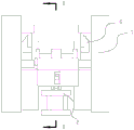
as shown in fig. 1, 2 and 3, the denitration catalyst cutting mechanism comprises tool holders 1 arranged in a mirror image manner, and a transfer mechanism 2 arranged between the tool holders 1; the tool rest 1 is provided with a feeding mechanism 11 capable of reciprocating, the limit positions of two ends of the feeding mechanism 11 are a first station and a second station, when in cutting, a piece to be cut is placed on the feeding mechanism, and the piece to be cut moves from the first station to the second station; be equipped with cutter 12 on the knife rest, the direction of cutter 12 intersects with the direction of feed, and cutter 12 can slope setting or perpendicular setting, and in this embodiment, cutter 12 is the perpendicular setting, and the upper and lower position of cutter 12 is equipped with fixing support, makes the both ends of catalyst cut into the perpendicular, and when two cutter positions were fixed, be convenient for cut into the denitration catalyst of uniform size, the regularity of assurance same batch of product.
The feeding mechanism 11 comprises a first air cylinder 111, a sliding block (or a sliding groove) and a bracket 112, wherein the bracket 112 is fixed on the sliding block, the sliding groove (or the sliding block) is further arranged on the tool rest, the sliding block is in sliding connection with the sliding groove, the first air cylinder 111 is fixed on the tool rest 1, and the telescopic end of the first air cylinder 111 is fixedly connected with the sliding block; the feeding of the denitration catalyst is realized through the cooperation of the first cylinder 111 and the slide block with the chute, the cutting of the two ends is realized, and the feeding length is at least equal to the length of the diagonal line of the denitration catalyst 5. The cross section of the bracket 112 is a V-shaped structure. The V-shaped support is more stable, and in order to better clamp the object, the included angle of the V-shaped support can be 90 degrees, and the V-shaped support is symmetrically arranged on the sliding block.
The base 21 comprises a top plate 211, a bottom plate 212 and at least one second cylinder 213, wherein the top plate 211 and the bottom plate 212 are arranged in parallel, and the second cylinder 213 is installed between the top plate 211 and the bottom plate 212. The first transfer rod 22 and the second transfer rod 23 can be rotated by a motor, or other mechanisms capable of rotating in the prior art can be applied thereto; the first transfer lever 22 and the second transfer lever 23 may be controlled by separate motors.
Referring to fig. 4, a transfer rack 24 is disposed on the top of each of the first transfer rod 22 and the second transfer rod 23, and the cross section of the transfer rack 24 is a V-shaped structure. Wherein, the included angle between the extreme positions of the rotation of the first transfer lever 22 and the second transfer lever 23 is 45 degrees. Similarly, the same setting of transport frame 24 is the V type, and the contained angle is 90 degrees, and when getting the material, the level form is personally submitted to the inboard of V type, is convenient for connect the material and get the material.
In the embodiment, the cutting machine further comprises a first conveying belt 3 for conveying a to-be-cut piece and a second conveying belt 4 for conveying a finished product, wherein the first conveying belt 3 and the second conveying belt 4 are respectively arranged on two sides of the cutting mechanism, one end of the first conveying belt 3, which is close to the cutter rest 1, is a material taking position, and one end of the second conveying belt 4, which is close to the cutter rest 1, is a material discharging position; the pieces to be cut are carried by the first conveyor belt 3 forward onto the first transfer bar 22 and the finished products are carried by the second conveyor belt 4 to the baling station. Further realize mechanized operation, use manpower sparingly.
In the embodiment, the dust-removing device further comprises a blowing mechanism 6 for blowing off dust generated during cutting, wherein the blowing mechanism 6 is arranged on two sides of the piece to be cut and is blown to be parallel to the piece to be cut; not limited to this, other blowing mechanisms may be used.
The utility model discloses a first transport pole 22 will wait to cut the piece and transport to the top of first station department by getting material department, will wait to cut the piece and arrange the back in feeding mechanism, first transport pole 22 descends and rotates to getting material department position after descending, at this moment, can wait to cut the piece with the second and transport to first transport pole 22 on, by the action of first cylinder 111, feed, cutter 12 cuts the both ends of denitration catalyst, when transporting to the second station, accomplish the cutting, at this moment, second transport pole 23 rises perpendicularly, and rotatory to ejection of compact department after holding up the finished product (at this moment, feeding mechanism gets back to first station), transport the finished product out, wait that feeding mechanism 2 returns to first station department, first transport pole rotates to first station department, descend and put down the second and wait to cut the piece, carry out the cutting of next work piece; the process has the advantages of no need of manual operation, mechanized production, high efficiency and high safety index.
Example two:
as shown in fig. 5, 6 and 7, the present embodiment is different from the first embodiment in that the transfer mechanism 2 further includes a connecting rod 25;
the two ends of the connecting rod 25 are rotatably connected with the middle part of the first transfer rod 22 and the middle part of the second transfer rod 23, the first transfer rod 22, the second transfer rod 23 and the connecting rod 25 form a link mechanism, and when the first transfer rod 22 or the second transfer rod 23 is vertical, an included angle between the first transfer rod 22 and the second transfer rod 23 is 45 degrees;
as shown in fig. 8(a) to 8(f), the transfer schematic process in the present embodiment:
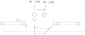
as shown in fig. 8(a), at this time, the second cylinder 213 raises the base 21 to the highest position, the first transfer rod 22 is at 45 degrees to the vertical direction, the inner side surface of the left side plate of the transfer frame 24 is flush with or slightly lower than the upper belt of the first transfer belt 3, the first transfer belt 3 rotates, the material a falls on the transfer frame 24 of the first transfer rod 22, at this time, the second transfer rod 23 is in a vertical state, the first transfer rod 22 can rotate after receiving the material a, because of the existence of the connecting rod 25, the movement of the whole link mechanism can be realized by using one motor, the first transfer rod 22 rotates, and the second transfer rod 23 realizes linkage;
as shown in fig. 8(b), the first transfer rod 22 rotates clockwise to transfer to the first station, and at the same time, the second transfer rod 23 rotates to the discharging position, at this time, the height of the material a is slightly higher than the position of the bracket 112, the second cylinder 213 acts to drive the first transfer rod 22 and the second transfer rod 23 to descend, and the two ends of the material a are placed on the bracket 112;
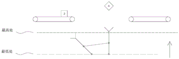
as shown in fig. 8(c), after the two ends of the material a are placed on the support 112, the first cylinder 111 acts to drive the support 112 to move forward, and since the support is of a V-shaped structure, the denitration catalyst 5 can be positioned, and the cutter 12 cuts the material a; in this process, the first transfer lever 22 is rotated counterclockwise while the second transfer lever 23 is rotated counterclockwise;
as shown in fig. 8(d), the material a is cut, at this time, the first transfer rod 22 rotates counterclockwise to below the material taking position, and at the same time, the second transfer rod 23 rotates counterclockwise to below the second station; the second cylinder 213 acts to drive the first transfer rod 22 and the second transfer rod 23 to ascend, wherein the highest position in the figure refers to the highest position of the top surface of the base 21, and the lowest position is the lowest position of the top surface of the base 21;
as shown in fig. 8(e), the first transfer lever 22 and the second transfer lever 23 are lifted to the highest position, and at this time, the material B is fed to the transfer rack 24 of the first transfer lever 22, and the transfer rack 24 of the second transfer lever 23 also holds the material a;
as shown in fig. 8(d), the first transfer rod 22 rotates clockwise to the upper side of the first station, meanwhile, the second transfer rod 23 rotates clockwise to the discharging position, the second conveyer belt 4 conveys the material a out, and at this time, the processing of the material a is completed.
Example three:
on the basis of the first embodiment or the second embodiment, the waste material processing device further comprises a waste material conveying belt and a waste material box, wherein one end of the waste material conveying belt is arranged below the cutter, and the other end of the waste material conveying belt is provided with the waste material box. Can collect the waste material, carry out recycle, avoid the production place to be mixed and disorderly.
Besides, the blowing mechanisms can be arranged at the two ends of the cutting position and in the transportation process, dust generated during cutting is cleaned, and the blowing mechanisms in the prior art are adopted, so that the requirement that wind energy can blow off the dust is met.
The above embodiments are only used to illustrate the technical solution of the present invention, and not to limit it; although the present invention has been described in detail with reference to the foregoing embodiments, it should be understood by those skilled in the art that: the technical solutions described in the foregoing embodiments may still be modified, or some technical features may be equivalently replaced; such modifications and substitutions do not depart from the spirit and scope of the present invention in its corresponding aspects.
Claims (9)
1. The denitration catalyst cutting mechanism is characterized by comprising tool rests arranged in a mirror image mode and a transfer mechanism arranged between the tool rests;
the tool rest is provided with a feeding mechanism capable of reciprocating, the limit positions of the two ends of the feeding mechanism are a first station and a second station, when in cutting, a piece to be cut is placed on the feeding mechanism, and the piece to be cut moves from the first station to the second station; a cutter is arranged on the cutter rest, and the direction of the cutter is intersected with the feeding direction;
the transferring mechanism comprises a base capable of moving up and down, a first transferring rod and a second transferring rod, the first transferring rod is rotatably connected to the base, the second transferring rod is rotatably connected to the base, the rotating limit positions of the first transferring rod are a material taking position and a first station position of a piece to be cut, and the rotating limit positions of the second transferring rod are a finished product discharging position and a second station position;
the cutting machine also comprises a first conveying belt for conveying the workpiece to be cut and a second conveying belt for conveying a finished product, wherein the first conveying belt and the second conveying belt are respectively arranged at two sides of the cutting mechanism, one end of the first conveying belt close to the cutter rest is a material taking position, and one end of the second conveying belt close to the cutter rest is a material discharging position;
the cutting device is characterized by further comprising a blowing mechanism for blowing off dust generated during cutting, wherein the blowing mechanism is arranged on two sides of the piece to be cut and blows to the direction parallel to the piece to be cut.
2. The denitration catalyst cutting mechanism of claim 1, wherein the feeding mechanism comprises a first cylinder, a sliding block and a support, the support is fixed on the sliding block, a sliding groove is further formed in the tool rest, the sliding block is connected with the sliding groove in a sliding mode, the first cylinder is fixed on the tool rest, and a telescopic end of the first cylinder is fixedly connected with the sliding block.
3. The denitration catalyst cutting mechanism according to claim 2, wherein the cross section of the support has a V-shaped structure.
4. The denitration catalyst cutting mechanism of claim 1, wherein a transfer frame is arranged on the top of each of the first transfer rod and the second transfer rod, and the cross section of the transfer frame is of a V-shaped structure.
5. The denitration catalyst cutting mechanism according to claim 1, wherein an angle between the extreme positions of rotation of the first transfer lever and the second transfer lever is 45 °.
6. The denitration catalyst cutting mechanism of claim 1, wherein the direction of the cutter is perpendicular to the feeding direction.
7. The denitration catalyst cutting mechanism of claim 1, further comprising a connecting rod, wherein two ends of the connecting rod are rotatably connected with the middle part of the first transfer rod and the middle part of the second transfer rod, and when the first transfer rod or the second transfer rod is in a vertical state, an included angle between the first transfer rod and the second transfer rod is 45 degrees.
8. The denitration catalyst cutting mechanism of claim 1, wherein the base comprises a top plate, a bottom plate, and at least one second cylinder, the top plate and the bottom plate are arranged in parallel, and the second cylinder is installed between the top plate and the bottom plate.
9. The denitration catalyst cutting mechanism of claim 1, further comprising a waste material conveyor belt and a waste material bin, wherein one end of the waste material conveyor belt is disposed below the cutter, and the other end of the waste material conveyor belt is provided with the waste material bin.
Priority Applications (1)
| Application Number | Priority Date | Filing Date | Title |
|---|---|---|---|
| CN201921609507.1U CN210879782U (en) | 2019-09-25 | 2019-09-25 | Denitration catalyst cutting mechanism |
Applications Claiming Priority (1)
| Application Number | Priority Date | Filing Date | Title |
|---|---|---|---|
| CN201921609507.1U CN210879782U (en) | 2019-09-25 | 2019-09-25 | Denitration catalyst cutting mechanism |
Publications (1)
| Publication Number | Publication Date |
|---|---|
| CN210879782U true CN210879782U (en) | 2020-06-30 |
Family
ID=71339981
Family Applications (1)
| Application Number | Title | Priority Date | Filing Date |
|---|---|---|---|
| CN201921609507.1U Active CN210879782U (en) | 2019-09-25 | 2019-09-25 | Denitration catalyst cutting mechanism |
Country Status (1)
| Country | Link |
|---|---|
| CN (1) | CN210879782U (en) |
Cited By (1)
| Publication number | Priority date | Publication date | Assignee | Title |
|---|---|---|---|---|
| CN110614658A (en) * | 2019-09-25 | 2019-12-27 | 安徽元琛环保科技股份有限公司 | Denitration catalyst cutting mechanism |
-
2019
- 2019-09-25 CN CN201921609507.1U patent/CN210879782U/en active Active
Cited By (1)
| Publication number | Priority date | Publication date | Assignee | Title |
|---|---|---|---|---|
| CN110614658A (en) * | 2019-09-25 | 2019-12-27 | 安徽元琛环保科技股份有限公司 | Denitration catalyst cutting mechanism |
Similar Documents
| Publication | Publication Date | Title |
|---|---|---|
| CN203696572U (en) | Double-warehouse automatic feeding and discharging production line for laser cutting machine | |
| CN109940286B (en) | Full-automatic uncoiling laser cutting production line | |
| CN105150251A (en) | Full-automatic board separating machine | |
| CN214299878U (en) | Automatic glass cutting device | |
| KR20120098450A (en) | Flexible unloading apparatus for pipe machining apparatus | |
| CN206201176U (en) | Building walling intelligent multifunctional production line | |
| CN110405923B (en) | Mud cutting equipment for ceramics making | |
| CN210879782U (en) | Denitration catalyst cutting mechanism | |
| CN210099247U (en) | Full-automatic uncoiling laser cutting production line | |
| CN105819232A (en) | Automatic stacking device and stacking method thereof | |
| CN106392333B (en) | Bumper Laser Jet conveys automatic assembly line | |
| CN210755883U (en) | Laser pipe cutting equipment | |
| CN210475894U (en) | Automatic unloader that goes up of laser cutting | |
| CN210677945U (en) | Multi-specification die blank cutting equipment | |
| CN110614658A (en) | Denitration catalyst cutting mechanism | |
| CN211194296U (en) | Automatic unloader that goes up of refractory material press robot | |
| CN205634205U (en) | Automatic stacking device | |
| CN214353368U (en) | Automatic drilling equipment of glass | |
| CN202279523U (en) | Discharge tray mechanism | |
| CN214819009U (en) | Cutting, picking and placing device for dot-free plastic products | |
| CN212245252U (en) | Automatic frame type discharging mechanism | |
| CN211365831U (en) | Automatic unloading and go up sorting warehouse entry device of member | |
| CN210880506U (en) | Laundry detergent holds bottle clout rotary-cut device | |
| CN210875368U (en) | Denitration catalyst extrusion feeding device | |
| CN105750739A (en) | Laser template machining equipment with storage mechanism |
Legal Events
| Date | Code | Title | Description |
|---|---|---|---|
| GR01 | Patent grant | ||
| GR01 | Patent grant |