CN210703609U - Workbench lifting mechanism - Google Patents
Workbench lifting mechanism Download PDFInfo
- Publication number
- CN210703609U CN210703609U CN201921573904.8U CN201921573904U CN210703609U CN 210703609 U CN210703609 U CN 210703609U CN 201921573904 U CN201921573904 U CN 201921573904U CN 210703609 U CN210703609 U CN 210703609U
- Authority
- CN
- China
- Prior art keywords
- rack
- pole portion
- base
- workstation
- connecting rod
- Prior art date
- Legal status (The legal status is an assumption and is not a legal conclusion. Google has not performed a legal analysis and makes no representation as to the accuracy of the status listed.)
- Active
Links
Images

Abstract
The utility model provides a workstation elevating system, relate to the machinery processing technology field, it includes the base and sets up the workstation in the base top, be equipped with the slide rail on the base, sliding connection has the rack on the slide rail, the one end of rack is connected with the cylinder that is used for promoting or stimulates the rack and remove, install the bearing frame on the base, install a pivot through the bearing in the bearing frame, the one end of pivot stretches out and installs the gear that can rotate with the pivot is synchronous from the bearing frame, wheel and rack toothing, a pendulum rod of fixedly connected with in the pivot, the one end of pendulum rod articulates there is a connecting rod, the bottom demountable installation of workstation has the lug, the one end of connecting rod is articulated with the lug, vertically on the base be provided with two guide pillars, two guide pillars. The utility model discloses a workstation can go up and down automatically to light drive the work piece and remove to machining-position or leave machining-position, reduce the labour, improve production efficiency.
Description
Technical Field
The utility model belongs to the technical field of the machining technique and specifically relates to indicate a workstation elevating system.
Background
In some semi-automatic machining processes, a machining head is in a fixed position, a worker can work a workpiece by matching with the machining head after lifting or moving the workpiece to a fixed height, the traditional operation method is that the worker manually places the workpiece on a movable workbench, then the workbench is moved to move the workpiece to the position of the machining head for machining, the workbench is moved away after machining is finished, the workpiece is placed into the next workpiece after being taken down, and the workbench is continuously moved to match the workpiece with the machining head, so that the production efficiency is delayed and the labor force of the worker is increased.
SUMMERY OF THE UTILITY MODEL
The utility model aims to solve the problem that a workstation elevating system is provided, put the work piece back on the workstation, the workstation can go up and down automatically to light drive the work piece and remove to processing station or leave processing station, reduce the labour, improve production efficiency.
In order to solve the technical problem, the utility model discloses a following technical scheme: the utility model provides a workbench lifting mechanism, includes the base and sets up the workstation in the base top, be equipped with the slide rail on the base, sliding connection has the rack on the slide rail, the one end of rack is connected with and is used for promoting or stimulate the cylinder that the rack removed, install the bearing frame on the base, install a pivot through the bearing in the bearing frame, the one end of pivot is stretched out and is installed the gear that can rotate with the pivot is synchronous from the bearing frame, wheel and rack toothing, a pendulum rod of fixedly connected with in the pivot, the one end of pendulum rod articulates there is a connecting rod, the bottom demountable installation of workstation has the lug, the one end and the lug of connecting rod are articulated, vertically on the base be provided with two guide pillars, two guide pillars pass the workstation and are used for the guide effect.
Preferably, the connecting rod includes upper rod portion and lower rod portion, upper rod portion and lower rod portion are equipped with the external screw thread respectively, upper rod portion and lower rod portion are connected with an adjusting nut respectively, upper rod portion and lower rod portion are through the bushing of an in-band screw thread, the rotating the sleeve pipe, the interval of adjustable upper rod portion lower extreme and lower rod portion upper end, and then adjust the length of connecting rod, thereby adjust the lift height range of workstation.
More preferably, the top end of the guide pillar is provided with a limiting block.
More preferably, the workbench is provided with two through holes, each through hole is provided with a guide sleeve, and the guide sleeves are sleeved on the guide pillars and can move up and down along the guide pillars.
More preferably, one end of the piston rod of the cylinder is connected with a push block, and the push block is in threaded connection with one end of the rack.
The beneficial effects of the utility model reside in that: after the work piece is put on the workstation, start the cylinder, make the piston rod of cylinder promote the rack and remove, thereby can make the gear take place to rotate, and then can drive the pivot synchronous rotation, meanwhile, the pendulum rod takes place to swing and takes the activity of pulling connecting rod, finally make the connecting rod can promote or the pulling workstation reciprocate along the guide pillar, realize the automatic rising of workstation, thereby easily drive the work piece and remove to processing station or leave processing station, reduce the labour in very big degree, improve production efficiency.
Drawings
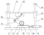
Fig. 1 is a schematic overall structure diagram in an embodiment of the present invention;
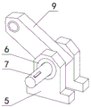
FIG. 2 is a schematic view of a connection structure of a bearing seat, a bearing and a swing rod in the embodiment;
FIG. 3 is a schematic sectional view of the connecting rod in the embodiment.
The reference signs are:
1-base 2-slide rail 3-rack
4-cylinder 5-bearing seat 6-bearing
7-rotating shaft 8-gear 9-swing rod
10-connecting rod 10 a-upper rod portion 10 b-lower rod portion
10 c-adjusting nut 10 d-sleeve 11-workbench
12-projection 13-guide post 14-limiting block
15-guide sleeve 16-push block.
Detailed Description
In order to facilitate understanding of those skilled in the art, the present invention will be further described with reference to the following examples and drawings, which are not intended to limit the present invention.
It should be noted that, in the present invention, unless otherwise explicitly specified or limited, the terms "mounted," "connected," "fixed," and the like are to be construed broadly, and may be, for example, fixedly connected, detachably connected, or integrally connected; they may be connected directly or indirectly through intervening media, or they may be interconnected between two elements. The specific meaning of the above terms in the present invention can be understood according to specific situations by those skilled in the art.
Furthermore, in the present disclosure, unless explicitly stated or limited otherwise, the first feature "on" or "under" the second feature may comprise direct contact of the first and second features, or may comprise contact of the first and second features not directly but through another feature therebetween. Also, the first feature being "on," "above" and "over" the second feature includes the first feature being directly on and obliquely above the second feature, or merely indicating that the first feature is at a higher level than the second feature. A first feature being "under," "below," and "beneath" a second feature includes the first feature being directly under and obliquely below the second feature, or simply meaning that the first feature is at a lesser elevation than the second feature. The terms "upper", "lower", "front", "rear", "left", "right", "vertical", "horizontal", "top", "bottom", "inner", "outer", and the like, indicate orientations or positional relationships based on the orientations or positional relationships shown in the drawings, and are only for convenience in describing the present invention and simplifying the description, but do not indicate or imply that the device or element referred to must have a particular orientation, be constructed and operated in a particular orientation, and thus, should not be construed as limiting the present invention.
As shown in fig. 1-3, a workbench lifting mechanism includes a base 1 and a workbench 11 disposed above the base, a sliding rail 2 is disposed on the base 1, a rack 3 is slidably connected to the sliding rail 2, one end of the rack 3 is connected to a cylinder 4 for pushing or pulling the rack 3 to move, a bearing seat 5 is mounted on the base 1, a rotating shaft 7 is mounted in the bearing seat 5 through a bearing 6, one end of the rotating shaft 7 extends from the bearing seat 5 and is provided with a gear 8 capable of rotating synchronously with the rotating shaft 7, the gear 8 is engaged with the rack 3, the rotating shaft 7 is fixedly connected with a swing rod 9, one end of the swing rod 9 is hinged with a connecting rod 10, a bump 12 is detachably mounted at the bottom of the workbench 11, one end of the connecting rod 10 is hinged with the bump 12, two guide posts 13 are vertically disposed on the base 1, and the two guide posts 13.
The workstation elevating system that above-mentioned embodiment provided is at the during operation, at first the work piece is put back on workstation 11, start cylinder 4, make the piston rod of cylinder 4 promote rack 3 and remove, thereby can make gear 8 take place to rotate, and then can drive pivot 7 synchronous rotation, meanwhile, pendulum rod 9 takes place to swing and takes the activity of pulling connecting rod 10, finally make connecting rod 10 can promote or pull workstation 11 and reciprocate along guide pillar 13, realize the automatic rising of workstation 11, thereby easily drive the work piece and remove to the processing station or leave the processing station, reduce the labour in very big degree, and the production efficiency is improved.
Preferably, as shown in fig. 3, the connecting rod 10 includes an upper rod portion 10a and a lower rod portion 10b, the upper rod portion 10a and the lower rod portion 10b are respectively provided with an external thread, the upper rod portion 10a and the lower rod portion 10b are respectively connected with an adjusting nut 10c, the upper rod portion 10a and the lower rod portion 10b are connected through a sleeve 10d with an internal thread, the sleeve 10d is rotated to adjust a distance between a lower end of the upper rod portion 10a and an upper end of the lower rod portion 10b, and further adjust a length of the connecting rod 10, so that a lifting height range of the worktable 11 can be adjusted, and the two adjusting nuts 10c can be adjusted to respectively abut against two ends of the sleeve 10d, so as to perform a limiting function and prevent the sleeve 10. The structure is simple, and the purpose of adjusting the lifting height range of the workbench 11 can be easily realized.
More preferably, a limit block 14 is arranged at the top end of the guide post 13, so that the workbench 11 is ensured not to be separated from the guide post 13 due to failure in the moving process, and a workpiece is protected.
More preferably, the worktable 11 is provided with two through holes (not shown in the drawings), the through holes are provided with guide sleeves 15, and the guide sleeves 15 are sleeved on the guide posts 13 and can move up and down along the guide posts 13, so that the lifting action of the worktable 11 can be smoother.
In addition, in this embodiment, the one end of the piston rod of cylinder 4 still is connected with ejector pad 16, and ejector pad 16 passes through threaded connection with the one end of rack 3, and this structure can easily be dismantled to be convenient for later maintenance or replacement part.
The above-mentioned embodiment is the utility model discloses the implementation scheme of preferred, in addition, the utility model discloses can also realize by other modes, any obvious replacement is all within the protection scope of the utility model under the prerequisite that does not deviate from this technical scheme design.
In order to make it easier for those skilled in the art to understand the improvement of the present invention over the prior art, some drawings and descriptions of the present invention have been simplified, and in order to clarify, some other elements have been omitted from this document, those skilled in the art should recognize that these omitted elements may also constitute the content of the present invention.
Claims (5)
1. The utility model provides a workstation elevating system, includes base (1) and sets up workstation (11) in the base top, its characterized in that: the automatic lifting device is characterized in that a sliding rail (2) is arranged on the base (1), a rack (3) is connected to the sliding rail (2), one end of the rack (3) is connected with a cylinder (4) used for pushing or pulling the rack (3) to move, a bearing seat (5) is installed on the base (1), a rotating shaft (7) is installed in the bearing seat (5) through a bearing (6), one end of the rotating shaft (7) extends out of the bearing seat (5) and is provided with a gear (8) capable of rotating synchronously with the rotating shaft (7), the gear (8) is meshed with the rack (3), the rotating shaft (7) is fixedly connected with a swing rod (9), one end of the swing rod (9) is hinged with a connecting rod (10), a lug (12) is detachably installed at the bottom of the workbench (11), one end of the connecting rod (10) is hinged with the lug (12), two guide posts (13) are vertically arranged on the base, the two guide columns (13) penetrate through the workbench (11) and are used for guiding.
2. The table lifting mechanism of claim 1, wherein: connecting rod (10) are including last pole portion (10 a) and lower pole portion (10 b), go up pole portion (10 a) and lower pole portion (10 b) and be equipped with the external screw thread respectively, go up pole portion (10 a) and lower pole portion (10 b) and be connected with an adjusting nut (10 c) respectively, go up pole portion (10 a) and lower pole portion (10 b) and connect through a sleeve pipe (10 d) of in-band screw thread, screw sleeve pipe (10 d), the interval of adjustable pole portion (10 a) lower extreme and lower pole portion (10 b) upper end, and then adjust the length of connecting rod (10), thereby adjust the lift height range of workstation (11).
3. The table lifting mechanism of claim 1, wherein: the top end of the guide post (13) is provided with a limiting block (14).
4. The table lifting mechanism of claim 3, wherein: two through holes are formed in the workbench (11), guide sleeves (15) are installed in the through holes, and the guide columns (13) are sleeved with the guide sleeves (15) and can move up and down along the guide columns (13).
5. The table lifting mechanism of claim 1, wherein: one end of a piston rod of the air cylinder (4) is connected with a push block (16), and the push block (16) is connected with one end of the rack (3) through threads.
Priority Applications (1)
| Application Number | Priority Date | Filing Date | Title |
|---|---|---|---|
| CN201921573904.8U CN210703609U (en) | 2019-09-20 | 2019-09-20 | Workbench lifting mechanism |
Applications Claiming Priority (1)
| Application Number | Priority Date | Filing Date | Title |
|---|---|---|---|
| CN201921573904.8U CN210703609U (en) | 2019-09-20 | 2019-09-20 | Workbench lifting mechanism |
Publications (1)
| Publication Number | Publication Date |
|---|---|
| CN210703609U true CN210703609U (en) | 2020-06-09 |
Family
ID=70961181
Family Applications (1)
| Application Number | Title | Priority Date | Filing Date |
|---|---|---|---|
| CN201921573904.8U Active CN210703609U (en) | 2019-09-20 | 2019-09-20 | Workbench lifting mechanism |
Country Status (1)
| Country | Link |
|---|---|
| CN (1) | CN210703609U (en) |
Cited By (7)
| Publication number | Priority date | Publication date | Assignee | Title |
|---|---|---|---|---|
| CN112264677A (en) * | 2020-10-15 | 2021-01-26 | 北京金兆博高强度紧固件有限公司 | Tapping machine |
| CN112377768A (en) * | 2020-11-16 | 2021-02-19 | 铜仁学院 | Survey surveying equipment convenient to remove |
| CN113182884A (en) * | 2021-03-30 | 2021-07-30 | 山西华尧重工有限公司 | Self-positioning standard joint common-length shearing equipment and use method thereof |
| CN113845018A (en) * | 2021-09-02 | 2021-12-28 | 南京澳博工业智能科技研究院有限公司 | Metallurgical hoist convenient to multidirectional regulation |
| WO2022032793A1 (en) * | 2020-08-12 | 2022-02-17 | 吴江市和信机械制造厂 | Workbench for fitness equipment accessory machining |
| WO2022036669A1 (en) * | 2020-08-17 | 2022-02-24 | 南京智欧智能技术研究院有限公司 | Dual-side automatic grinding apparatus and grinding method therefor |
| CN114310811A (en) * | 2021-12-16 | 2022-04-12 | 西安理工大学 | Workpiece turnover mechanism |
-
2019
- 2019-09-20 CN CN201921573904.8U patent/CN210703609U/en active Active
Cited By (9)
| Publication number | Priority date | Publication date | Assignee | Title |
|---|---|---|---|---|
| WO2022032793A1 (en) * | 2020-08-12 | 2022-02-17 | 吴江市和信机械制造厂 | Workbench for fitness equipment accessory machining |
| WO2022036669A1 (en) * | 2020-08-17 | 2022-02-24 | 南京智欧智能技术研究院有限公司 | Dual-side automatic grinding apparatus and grinding method therefor |
| CN112264677A (en) * | 2020-10-15 | 2021-01-26 | 北京金兆博高强度紧固件有限公司 | Tapping machine |
| CN112377768A (en) * | 2020-11-16 | 2021-02-19 | 铜仁学院 | Survey surveying equipment convenient to remove |
| CN113182884A (en) * | 2021-03-30 | 2021-07-30 | 山西华尧重工有限公司 | Self-positioning standard joint common-length shearing equipment and use method thereof |
| CN113182884B (en) * | 2021-03-30 | 2022-10-14 | 山西华尧重工有限公司 | Self-positioning standard joint common-length shearing equipment and use method thereof |
| CN113845018A (en) * | 2021-09-02 | 2021-12-28 | 南京澳博工业智能科技研究院有限公司 | Metallurgical hoist convenient to multidirectional regulation |
| CN114310811A (en) * | 2021-12-16 | 2022-04-12 | 西安理工大学 | Workpiece turnover mechanism |
| CN114310811B (en) * | 2021-12-16 | 2024-02-27 | 西安理工大学 | Workpiece overturning mechanism |
Similar Documents
| Publication | Publication Date | Title |
|---|---|---|
| CN210703609U (en) | Workbench lifting mechanism | |
| CN105329647B (en) | The turning device of heavy lead-acid accumulator | |
| CN111774845B (en) | Automatic assembling device for motor rotor clamp spring | |
| CN204311149U (en) | Anode hang tool goes up product facility automatically | |
| CN105931892A (en) | Mounting mechanism of travel switch accessory assembling machine | |
| CN112589195A (en) | Multimedia platform box body thin plate shaping, conveying, clamping and cutting device | |
| CN210280847U (en) | Full-automatic pipe cutter | |
| CN206509689U (en) | A kind of tipper | |
| CN109047554A (en) | A kind of titanium cookware stamping equipment | |
| CN210525265U (en) | Lifting follow-up centering support mechanism of pipe cutting production line | |
| CN210848556U (en) | Anti-bending pipe cutting device | |
| CN211127491U (en) | Quick maintenance device of taking out stitches of motor | |
| CN110842301B (en) | Module cutting method for wavy cutting track | |
| CN210684270U (en) | Thick glove turn-over machine | |
| CN111618491A (en) | Automatic welding equipment for shaft parts with cooling liquid recovery function | |
| CN112239185A (en) | Lifting device for electric power overhaul | |
| CN203849247U (en) | Analog simulation material test stand with lifter | |
| CN214647383U (en) | Automatic assembling machine for solid tire of electric bicycle | |
| CN208825409U (en) | A kind of titanium cookware stamping equipment | |
| CN220465916U (en) | Paper card placing device under high stability | |
| CN204686388U (en) | The Working-Clip sleeve of Anchor Cable Anchorage is installed with two slideway automatic mounting machine | |
| CN214771776U (en) | Disassembling device for shafting component of crane | |
| CN217652277U (en) | Supporting structure for building engineering construction | |
| CN204584855U (en) | Race ring discharging gathering-device | |
| CN212087967U (en) | Automatic device that denucleates of walnut is pressed from both sides to date |
Legal Events
| Date | Code | Title | Description |
|---|---|---|---|
| GR01 | Patent grant | ||
| GR01 | Patent grant |