CN210656623U - Organic sludge anaerobic digestion device - Google Patents
Organic sludge anaerobic digestion device Download PDFInfo
- Publication number
- CN210656623U CN210656623U CN201921516622.4U CN201921516622U CN210656623U CN 210656623 U CN210656623 U CN 210656623U CN 201921516622 U CN201921516622 U CN 201921516622U CN 210656623 U CN210656623 U CN 210656623U
- Authority
- CN
- China
- Prior art keywords
- tank body
- stirring
- organic sludge
- anaerobic digestion
- wall
- Prior art date
- Legal status (The legal status is an assumption and is not a legal conclusion. Google has not performed a legal analysis and makes no representation as to the accuracy of the status listed.)
- Active
Links
Images


Abstract
The utility model relates to an organic sludge anaerobic digestion device, which designs a tank body into a structure combining an outer wall, an inner wall, a heat insulation material and a heat tracing pipe, hot water with the temperature of 35-55 degrees is blown into the heat tracing pipe through the heat tracing pipe in the initial use stage, the temperature in the tank body is quickly raised through the effect of the heat tracing pipe, so that anaerobic bacteria in the tank body can be quickly propagated to improve the treatment efficiency of the anaerobic digestion device, meanwhile, in order to ensure that the organic sludge entering the tank body can be fully combined with the anaerobic bacteria, the utility model adopts that a stirring motor is arranged at the top of the tank body, the stirring motor is utilized to drive a rotating frame to rotate, the bottom is input into the tank body through a feeding device to be overturned and mixed, thereby ensuring the full contact and mixing of the organic sludge in the tank body and the anaerobic bacteria and ensuring the reaction efficiency, and simultaneously, the utility model discloses utilize unified a agitator motor to drive two puddler motions simultaneously, improve its stirring mixing efficiency.
Description
Technical Field
The utility model relates to an organic solid useless treatment facility technical field, more specifically relates to an organic sludge anaerobic digestion device.
Background
With the rapid development of social economy in China, the acceleration of urbanization process and the rapid improvement of the living standard of people, garbage generated in the urban production and living process is rapidly increased, and the conditions of land occupation, environmental pollution and the influence on the health of people by household garbage are more obvious. The increasing of the amount of municipal domestic waste makes the waste treatment more and more difficult, and the problems of environmental pollution and the like caused by the increase gradually draw attention from all social circles.
In China, to realize industrialization, resource utilization, reduction and harmlessness of municipal domestic garbage, domestic garbage which is mixed for collection, has low content and heat value of recoverable substances and high water content and biodegradable organic content of the garbage must be confronted. In response to these problems, a wide variety of technologies have been applied, including recycling, landfill, incineration, and composting, among others.
Most of urban and rural domestic garbage and agricultural wastes have higher water content and organic matter content, at present, the urban garbage is treated by utilizing an anaerobic digestion treatment technology, so that the method has wider application at home and abroad, and particularly in Europe, the method for treating the organic garbage by using anaerobic digestion is greatly developed; anaerobic digestion has also been greatly developed for treating kitchen waste in japan and korea. The technology has high harmless degree, completely overcomes the influence of homology, and has high organic load bearing capacity.
Although there is a certain difference between the municipal refuse in China and the municipal refuse in foreign countries. But also can meet the requirement of domestic kitchen waste treatment through corresponding technical improvement and optimization. Anaerobic digestion is an effective method for realizing reduction, harmlessness and recycling of municipal waste. Anaerobic digestion can be controlled manually, so that the stability of organic waste is accelerated, the organic waste is harmless, biogas can be generated through anaerobic decomposition, renewable energy sources are obtained, and the organic waste is recycled.
The anaerobic digestion tank is used as a key device for anaerobic digestion treatment, and due to the large volume, digestive juice in the anaerobic digestion tank is heated, kept warm and stirred, so that the energy consumption is large, the operation cost is high, and the popularization of the urban comprehensive garbage anaerobic treatment is not facilitated.
To the defect that prior art exists, provide the utility model discloses.
SUMMERY OF THE UTILITY MODEL
The utility model provides an organic sludge anaerobic digestion device with low energy consumption and high digestion efficiency, which solves the technical problems of high energy consumption and low digestion efficiency of the existing anaerobic digestion tank.
According to one aspect of the utility model, the organic sludge anaerobic digestion device is provided, which comprises a tank body, wherein the bottom of the tank body is externally connected with a feeding device, and the top of the tank body is provided with an exhaust pipe; the tank body comprises an outer wall, an inner wall and a heat insulation material, the outer wall is wrapped outside the inner wall through the heat insulation material, a heat tracing pipe is embedded in the heat insulation material, and the heat tracing pipe is externally connected with a heat exchanger; the top of the tank body is also provided with a stirring motor, an output shaft of the stirring motor is externally connected with a rotating frame, the rotating frame is T-shaped, stirring rods are arranged at two sides of the rotating frame, and stirring blades are arranged on the stirring rods.
On the basis of the scheme, the rotating frame comprises a connecting shaft and an installation rod, the connecting shaft is fixedly connected with an output shaft of the stirring motor, the middle of the installation rod is connected with an output end of the connecting shaft, and the stirring rods are arranged on two sides of the installation rod.
On the basis of the scheme, the water pump is preferred, the inner wall is provided with a plurality of spray heads, and the spray heads are communicated with the water pump through water pipes.
On the basis of the scheme, the connecting shaft, the mounting rod and the stirring rod are preferably hollow, the stirring rod and the mounting rod are provided with spray heads, and the connecting shaft is communicated with the water pump through a water pipe.
On the basis of the scheme, the feeding device is preferably a screw conveyor.
The utility model relates to an organic sludge anaerobic digestion device, which designs a tank body into a structure combining an outer wall, an inner wall, a heat insulation material and a heat tracing pipe, hot water with the temperature of 35-55 degrees is blown into the heat tracing pipe through the heat tracing pipe in the initial use stage, the temperature in the tank body is quickly raised through the effect of the heat tracing pipe, so that anaerobic bacteria in the tank body can be quickly propagated to improve the treatment efficiency of the anaerobic digestion device, meanwhile, in order to ensure that the organic sludge entering the tank body can be fully combined with the anaerobic bacteria, the utility model adopts that a stirring motor is arranged at the top of the tank body, the stirring motor is utilized to drive a rotating frame to rotate, the bottom is input into the tank body through a feeding device to be overturned and mixed, thereby ensuring the full contact and mixing of the organic sludge in the tank body and the anaerobic bacteria and ensuring the reaction efficiency, and simultaneously, the utility model discloses utilize unified a agitator motor to drive two puddler motions simultaneously, improve its stirring mixing efficiency.
Drawings
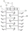
FIG. 1 is a schematic diagram of an anaerobic digestion apparatus for organic sludge according to the present invention;
FIG. 2 is a partial structural view of a stirring rod of the present invention;
fig. 3 is a structural diagram of the feeding device of the present invention.
Detailed Description
The following detailed description of the embodiments of the present invention is provided with reference to the accompanying drawings and examples. The following examples are intended to illustrate the invention, but are not intended to limit the scope of the invention.
Referring to fig. 1, the anaerobic digestion device for organic sludge of the present invention comprises a tank 10, a feed inlet 110 is disposed at the bottom of the tank 10 and is externally connected to a feeding device 11, a discharge outlet 120 is disposed at one side of the tank 10 opposite to the feed inlet 110, and an exhaust pipe 13 is disposed at the top of the tank 10; the tank body 10 comprises an outer wall 14, an inner wall 15 and a heat insulation material 16, wherein the outer wall 14 is wrapped outside the inner wall 15 through the heat insulation material 16, a heat tracing pipe 17 is embedded in the heat insulation material 16, and the heat tracing pipe 17 is externally connected with a heat exchanger; the top of the tank body 10 is also provided with a stirring motor 20, an output shaft of the stirring motor 20 is externally connected with a rotating frame 21, the rotating frame 21 is T-shaped, stirring rods 24 are arranged at two sides of the rotating frame 21, and stirring blades 26 are arranged on the stirring rods 24.
The utility model relates to an organic sludge anaerobic digestion device, which designs a tank body 10 into a structure combining an outer wall 14, an inner wall 15, a heat insulation material 16 and a heat tracing pipe 17, can bulge hot water with the temperature of 35-55 degrees into the heat tracing pipe 17 through the heat tracing pipe 17 external heat exchanger at the initial stage of use, and can quickly raise the temperature in the tank body 10 through the effect of the heat tracing pipe 17, so that anaerobic bacteria in the tank body 10 can quickly reach the temperature suitable for propagation, and can propagate in a large quantity, so as to improve the treatment efficiency of the anaerobic digestion device, meanwhile, in order to ensure that the organic sludge entering the tank body 10 can be fully combined with the anaerobic bacteria, the utility model adopts that a stirring motor 20 is arranged at the top of the tank body 10, the stirring motor 20 is utilized to drive a rotating frame 21 to rotate, and the bottom is input into the material in the tank body 10 through a feeding device 11 to, thereby in order to guarantee its inside organic mud and the abundant contact of anaerobism bacterium and mix, ensure its reaction efficiency, simultaneously, the utility model discloses utilize unified a agitator motor 20 can drive two puddlers 24 motions simultaneously, improve its stirring mixing efficiency.
It is worth explaining that, the utility model discloses a swivel mount 21 includes connecting axle 22 and installation pole 23, and connecting axle 22 links to each other with agitator motor 20's output shaft is fixed, and the middle part of installation pole 23 links to each other with connecting axle 22's output, and puddler 24 is installed in the both sides of installation pole 23. When the stirring motor 20 operates, the connecting shaft 22 is driven to rotate, so that the mounting rod 23 makes a circular motion with the connecting shaft 22 as a center, the stirring rod 24 mounted on the mounting rod 23 rotates around the center line of the tank body 10, and the stirring blades 26 on the stirring rod 24 interact with the organic sludge in the stirring tank, thereby realizing rapid mixing and stirring inside the stirring tank.
It is worth explaining, the utility model discloses a puddler 24 includes that the left side mixes the pole and the right side mixes the pole, and the stirring leaf 26 on the pole is mixed on the left side is along the crisscross setting about its length direction is even, and the stirring leaf 26 on the pole is mixed on the right side is then along the crisscross setting about its length direction is even, and the stirring leaf 26 that the pole is mixed near the right side on one side of mixing the pole and the stirring leaf 26 intercrossing setting that the pole is mixed near the left side on one side of mixing the pole with the right side to the left side of mixing the pole, specifically please see figure 2 and show to guarantee the.
Further, the utility model discloses still include a water pump, inner wall 15 facial make-up is equipped with a plurality of shower nozzles 25, and shower nozzle 25 leads to pipe and is linked together with the water pump. When the device is used, high-pressure water can be supplied into the tank body 10 through the water pump so as to treat the inside of the tank body 10.
The utility model discloses a connecting axle 22 and installation pole 23 and puddler 24 are the cavity form to be equipped with shower head 27 at puddler 24 and installation pole 23 facial make-up, and connecting axle 22 leads to pipe and is linked together with the water pump. High pressure water can be pumped into the stirring rod 24 and the mounting rod 23 by a water pump to improve the mixing effect. Preferably, in order to improve the conveying efficiency, the feeding device 11 of the present invention preferably uses a screw conveyor, and the specific structure is shown in fig. 3.
Finally, the method of the present application is only a preferred embodiment and is not intended to limit the scope of the present invention. Any modification, equivalent replacement, or improvement made within the spirit and principle of the present invention should be included in the protection scope of the present invention.
Claims (5)
1. An organic sludge anaerobic digestion device is characterized by comprising a tank body, wherein the bottom of the tank body is externally connected with a feeding device, and the top of the tank body is provided with an exhaust pipe; the tank body comprises an outer wall, an inner wall and a heat insulation material, the outer wall is wrapped outside the inner wall through the heat insulation material, a heat tracing pipe is embedded in the heat insulation material, and the heat tracing pipe is externally connected with a heat exchanger; the top of the tank body is also provided with a stirring motor, an output shaft of the stirring motor is externally connected with a rotating frame, the rotating frame is T-shaped, stirring rods are arranged at two sides of the rotating frame, and stirring blades are arranged on the stirring rods.
2. The anaerobic digestion device for organic sludge as claimed in claim 1, wherein said rotary frame includes a connecting shaft and a mounting rod, said connecting shaft is fixedly connected with the output shaft of said stirring motor, the middle portion of said mounting rod is connected with the output end of said connecting shaft, said stirring rod is installed on both sides of said mounting rod.
3. The anaerobic digestion device for organic sludge as claimed in claim 2, further comprising a water pump, wherein a plurality of nozzles are installed on the inner wall, and the nozzles are connected with the water pump through water pipes.
4. The anaerobic digestion device for organic sludge as claimed in claim 3, wherein said connection shaft, said mounting rod and said stirring rod are hollow, and spray heads are installed on said stirring rod and said mounting rod, and said connection shaft is connected with said water pump through water pipe.
5. The anaerobic digestion unit for organic sludge as claimed in claim 1, wherein said feeding means is a screw conveyor.
Priority Applications (1)
| Application Number | Priority Date | Filing Date | Title |
|---|---|---|---|
| CN201921516622.4U CN210656623U (en) | 2019-09-12 | 2019-09-12 | Organic sludge anaerobic digestion device |
Applications Claiming Priority (1)
| Application Number | Priority Date | Filing Date | Title |
|---|---|---|---|
| CN201921516622.4U CN210656623U (en) | 2019-09-12 | 2019-09-12 | Organic sludge anaerobic digestion device |
Publications (1)
| Publication Number | Publication Date |
|---|---|
| CN210656623U true CN210656623U (en) | 2020-06-02 |
Family
ID=70821368
Family Applications (1)
| Application Number | Title | Priority Date | Filing Date |
|---|---|---|---|
| CN201921516622.4U Active CN210656623U (en) | 2019-09-12 | 2019-09-12 | Organic sludge anaerobic digestion device |
Country Status (1)
| Country | Link |
|---|---|
| CN (1) | CN210656623U (en) |
Cited By (2)
| Publication number | Priority date | Publication date | Assignee | Title |
|---|---|---|---|---|
| CN113816579A (en) * | 2021-09-28 | 2021-12-21 | 中冶焦耐(大连)工程技术有限公司 | Sludge anaerobic digestion treatment device and method |
| CN116396108A (en) * | 2023-03-31 | 2023-07-07 | 湖南省农业环境生态研究所 | High-temperature rapid decomposing device |
-
2019
- 2019-09-12 CN CN201921516622.4U patent/CN210656623U/en active Active
Cited By (3)
| Publication number | Priority date | Publication date | Assignee | Title |
|---|---|---|---|---|
| CN113816579A (en) * | 2021-09-28 | 2021-12-21 | 中冶焦耐(大连)工程技术有限公司 | Sludge anaerobic digestion treatment device and method |
| CN116396108A (en) * | 2023-03-31 | 2023-07-07 | 湖南省农业环境生态研究所 | High-temperature rapid decomposing device |
| CN116396108B (en) * | 2023-03-31 | 2024-02-23 | 湖南省农业环境生态研究所 | High-temperature rapid decomposing device |
Similar Documents
| Publication | Publication Date | Title |
|---|---|---|
| CN202080994U (en) | Harmless and reducing real-time treatment system for sewage and sludge | |
| CN201409867Y (en) | Ecological environmental toilet without water | |
| CN103130320B (en) | A kind of wind energy oxygen supply type rural domestic sewage treating device and method | |
| CN210656623U (en) | Organic sludge anaerobic digestion device | |
| CN103964903A (en) | Anaerobic and aerobic fermentation coupling device for organic garbage treatment | |
| CN207596746U (en) | Integrated automation consumer garbage compost processing equipment | |
| CN202830024U (en) | Anaerobic digestion integrated device for organic household garbage | |
| CN206052022U (en) | A kind of device of organic solid castoff dry-type anaerobic fermentation | |
| CN111215432A (en) | Three-stage integrated treatment system and method for organic biomass garbage | |
| CN207288309U (en) | A kind of Environmental-protection garbage handles dry sterilizing device | |
| CN206767951U (en) | A kind of solar energy consumer garbage compost processing equipment | |
| CN103086758A (en) | Anaerobic composting process applicable to small-scale kitchen waste treatment | |
| CN206014920U (en) | Biomass ferment consersion unit | |
| CN204220605U (en) | The comprehensive food waste treatment system of high efficiency low power consuming | |
| CN202390245U (en) | Wind energy oxygen supplying type rural domestic sewage treating device | |
| CN109824223A (en) | A kind of sludge treatment equipment of closed rotary input and output material | |
| CN204939315U (en) | There is the organic solid waste mineralising fermentation unit that aeration performance is stirred in temperature control | |
| CN104892039A (en) | Method used for converting kitchen solid residue into biologic bacterium preparations | |
| CN204939314U (en) | Convection agitation formula rubbish mineralising fermentation unit | |
| CN102321562B (en) | Method for producing biological agent by fermenting water hyacinth juice and fermentation device thereof | |
| CN203855525U (en) | Anaerobic and aerobic fermentation coupling device for treating organic wastes | |
| CN111998357A (en) | Hydrogen-rich energy source machine for kitchen waste | |
| CN101768542A (en) | Peristaltic anaerobic solid-state fermentation device used for organic acid fermentation | |
| CN212565795U (en) | Kitchen waste hydrogen-rich energy combustion system | |
| CN212456864U (en) | Hydrogen-rich energy source machine for kitchen waste |
Legal Events
| Date | Code | Title | Description |
|---|---|---|---|
| GR01 | Patent grant | ||
| GR01 | Patent grant |