CN210636879U - Parking energy storage robot - Google Patents
Parking energy storage robot Download PDFInfo
- Publication number
- CN210636879U CN210636879U CN201921201122.1U CN201921201122U CN210636879U CN 210636879 U CN210636879 U CN 210636879U CN 201921201122 U CN201921201122 U CN 201921201122U CN 210636879 U CN210636879 U CN 210636879U
- Authority
- CN
- China
- Prior art keywords
- lifting
- chain wheel
- rotating
- case
- transition gear
- Prior art date
- Legal status (The legal status is an assumption and is not a legal conclusion. Google has not performed a legal analysis and makes no representation as to the accuracy of the status listed.)
- Active
Links
Images


Classifications
-
- Y—GENERAL TAGGING OF NEW TECHNOLOGICAL DEVELOPMENTS; GENERAL TAGGING OF CROSS-SECTIONAL TECHNOLOGIES SPANNING OVER SEVERAL SECTIONS OF THE IPC; TECHNICAL SUBJECTS COVERED BY FORMER USPC CROSS-REFERENCE ART COLLECTIONS [XRACs] AND DIGESTS
- Y02—TECHNOLOGIES OR APPLICATIONS FOR MITIGATION OR ADAPTATION AGAINST CLIMATE CHANGE
- Y02T—CLIMATE CHANGE MITIGATION TECHNOLOGIES RELATED TO TRANSPORTATION
- Y02T10/00—Road transport of goods or passengers
- Y02T10/60—Other road transportation technologies with climate change mitigation effect
- Y02T10/70—Energy storage systems for electromobility, e.g. batteries
-
- Y—GENERAL TAGGING OF NEW TECHNOLOGICAL DEVELOPMENTS; GENERAL TAGGING OF CROSS-SECTIONAL TECHNOLOGIES SPANNING OVER SEVERAL SECTIONS OF THE IPC; TECHNICAL SUBJECTS COVERED BY FORMER USPC CROSS-REFERENCE ART COLLECTIONS [XRACs] AND DIGESTS
- Y02—TECHNOLOGIES OR APPLICATIONS FOR MITIGATION OR ADAPTATION AGAINST CLIMATE CHANGE
- Y02T—CLIMATE CHANGE MITIGATION TECHNOLOGIES RELATED TO TRANSPORTATION
- Y02T10/00—Road transport of goods or passengers
- Y02T10/60—Other road transportation technologies with climate change mitigation effect
- Y02T10/7072—Electromobility specific charging systems or methods for batteries, ultracapacitors, supercapacitors or double-layer capacitors
-
- Y—GENERAL TAGGING OF NEW TECHNOLOGICAL DEVELOPMENTS; GENERAL TAGGING OF CROSS-SECTIONAL TECHNOLOGIES SPANNING OVER SEVERAL SECTIONS OF THE IPC; TECHNICAL SUBJECTS COVERED BY FORMER USPC CROSS-REFERENCE ART COLLECTIONS [XRACs] AND DIGESTS
- Y02—TECHNOLOGIES OR APPLICATIONS FOR MITIGATION OR ADAPTATION AGAINST CLIMATE CHANGE
- Y02T—CLIMATE CHANGE MITIGATION TECHNOLOGIES RELATED TO TRANSPORTATION
- Y02T90/00—Enabling technologies or technologies with a potential or indirect contribution to GHG emissions mitigation
- Y02T90/10—Technologies relating to charging of electric vehicles
- Y02T90/14—Plug-in electric vehicles
Abstract
The utility model discloses a parking energy storage robot, which comprises two tracks arranged on the ground, wherein a case which can move in a reciprocating manner is arranged on the tracks, the case comprises a walking mechanism and a rotating mechanism which can drive the case to move, the front end of the case is connected with a stand which is driven by the rotating mechanism to rotate, the upper end of the stand is provided with a lifting mechanism, the stand is provided with a vehicle carrying plate which can slide up and down under the driving of the lifting mechanism, and the case is provided with at least one accumulator box with a charging gun; the lifting mechanism adopts a transmission mode of a lifting driving chain wheel, a lifting bearing chain wheel, a lifting driven chain wheel and a lifting chain wheel, so that the lifting is stable and the reliability is high; the rotary mounting mechanism can enable the vehicle carrying plate to rotate, so that a driver can conveniently park; the utility model is provided with two-layer charging, which improves the number of the original charging parking spaces by half and improves the charging number in a single unit time to the maximum extent; the number of the charges in unit time is increased, and meanwhile, the occupied area is reduced.
Description
Technical Field
The utility model belongs to the technical field of the equipment of parking, especially, relate to an energy storage robot parks.
Background
The problem of ubiquitous parking of vehicles is a result of social, economic and traffic development in cities to some extent, and the development of three-dimensional parking facilities has been successful both technically and empirically in foreign countries, especially in japan for nearly 30-40 years.
In order to save the ground space, the ground garage increasingly adopts the stereo garage. The existing stereo garage adopts a multilayer oval circulation mode, when a vehicle needs to be parked in an upper parking space, a circulation power device needs to be started, the original bottom parking space is lifted to the upper parking space, the parking direction is fixed, the vehicle needs to be driven to carry out backing and garage entry operation, and inconvenience is brought to driving; in addition, the existing parking equipment mostly adopts a steel wire rope to pull a parking space to lift, and the parking space can shake and swing in the cyclic ascending and descending processes of the parking space, so that the risk of vehicle damage is increased, and the safety is not high; the parking equipment is not provided with a charging device, and the electric vehicle needs to be charged by pulling a wire, so that the charging is very inconvenient.
SUMMERY OF THE UTILITY MODEL
To the above problem, the utility model provides an energy storage robot parks, fine solution park inconvenient, easy number damage vehicle and electric motor car ground charge tense, park the inconvenient problem of charging.
In order to realize the purpose, the utility model discloses a technical scheme as follows: a parking energy storage robot comprises two tracks arranged on the ground, wherein a case which moves in a reciprocating manner is arranged on the tracks, the case comprises a rotating mechanism and a traveling mechanism for driving the case to move, the front end of the case is connected with a stand column which is driven to rotate by the rotating mechanism, a lifting mechanism is arranged at the upper end of the stand column, a vehicle carrying plate which is driven to slide up and down by the lifting mechanism is arranged on the stand column, and at least one storage battery box with a charging gun is arranged on the case;
the traveling mechanism comprises a first speed reducing motor, the first speed reducing motor is connected with a traveling driving sprocket, the traveling driving sprocket is connected with a traveling driven sprocket arranged at the front end of the chassis through a traveling transmission chain, the traveling driven sprocket is sleeved on a traveling driving shaft and drives the traveling driving shaft to rotate, traveling driving gears are respectively arranged at two ends of the traveling driving shaft in a penetrating mode, the traveling driving gears are meshed with toothed rollers rolling on the track, and hanging wheels which are symmetrical about the track and are in contact with the track are arranged below the toothed rollers;
the rotating mechanism comprises a second speed reducing motor, the second speed reducing motor is connected with a rotating driving gear, the lower end of the upright post is connected with a rotating main shaft with teeth, the rotating main shaft is sleeved in a rotating seat fixed at the front end of the case, and a transition gear mechanism is arranged between the rotating driving gear and the rotating main shaft;
the lifting mechanism comprises a third speed reducing motor, the third speed reducing motor is connected with a lifting driving chain wheel, a lifting bearing chain wheel is arranged on one side of the lifting driving chain wheel, a lifting driven chain wheel is arranged below the lifting driving chain wheel, and the distance between the edge of the lifting driving chain wheel and the edge of the lifting bearing chain wheel is smaller than the diameter of the lifting driven chain wheel; the lifting driving chain wheel, the lifting bearing chain wheel and the lifting driven chain wheel are wound with lifting chains, and one end of each lifting chain is connected with the car carrying plate.
Furthermore, the first speed reduction motor is arranged at the rear end of the case, and the second speed reduction motor is arranged at the front end of the case.
Furthermore, the rear end of the case is provided with a roller wheel positioned on the track and a change gear matched with the roller wheel.
Furthermore, the transition gear mechanism comprises a first rotary transition gear, a second rotary transition gear and a third rotary transition gear meshed with the second rotary transition gear, the first rotary transition gear and the second rotary transition gear are both sleeved on the first rotary transition gear shaft, the third rotary transition gear is sleeved on the second rotary transition gear shaft, the first rotary transition gear shaft and the second rotary transition gear shaft are both fixed on the case, the first rotary transition gear is meshed with the rotary driving gear, and the third rotary transition gear is meshed with the teeth on the rotary main shaft.
Furthermore, one side of the lifting driving chain wheel, which is far away from the lifting bearing chain wheel, is provided with a pre-tightening wheel.
Furthermore, the upper end and the lower end of the rotating main shaft are provided with a roller double-row bearing and a plane bearing.
Furthermore, a charging gun is arranged on the vehicle carrying plate.
Furthermore, an anti-falling device is arranged on the vehicle carrying plate.
Compared with the prior art, the utility model discloses following beneficial effect has:
1. the rotating mechanism can rotate the vehicle carrying plate, when the vehicle carrying plate descends, the vehicle carrying plate rotates by 90 degrees, vehicles can directly drive into the vehicle carrying plate without backing and warehousing, then the vehicle carrying plate is lifted by the lifting mechanism and then rotates by 90 degrees to enter a two-layer parking space, and driving inconvenience is reduced.
2. The distance between the edge of the lifting driving chain wheel and the edge of the lifting driving chain wheel is smaller than the diameter of the lifting driven chain wheel, when a lifting chain is arranged around, the lifting driving chain wheel and the lifting driven chain wheel can be ensured to have more gear teeth meshed with the chain, so that the lifting chain is not easy to break away from the chain wheel, the reliability and the safety of the lifting device are improved, the lifting is stable enough, and vehicles are not easy to damage.
3. The electric storage box on the case can be charged while the electric automobile is parked, the functions are complete, the charging quantity in unit time is increased, and meanwhile, the occupied area is reduced; the endurance of the electric automobile can be met.
4. The gear wheel rolls on the rail, the change gear rolls on two sides of the rail, the change gear and the gear wheel with teeth cooperate to roll on the rail, the roller and the change gear are further arranged at the rear end of the case, when the vehicle carrying plate lifts a vehicle and the case walks on the rail, a good guiding effect can be achieved, the overturning moment of the stand column can be met, and the reliability of the novel use is improved.
5. The lifting driving chain wheel, the lifting bearing chain wheel and the lifting driven chain wheel are arranged at the upper end of the upright post in a centralized manner, and the assembly is easy.
6. The roller double-row bearing and the plane bearing are combined for use, so that the requirements for large axial force and overturning moment transmitted by the stand column are met, and good rotation is realized.
Drawings
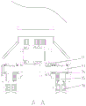
FIG. 1 is a front view of the present invention;
FIG. 2 is a schematic diagram of the structure inside the case;
FIG. 3 is a cross-sectional view of FIG. 2;
FIG. 4 is a schematic structural view of a rotating mechanism;
FIG. 5 is a schematic view of the lifting mechanism;
FIG. 6 is a flowchart illustrating a parking and warehousing charging process of an electric vehicle;
fig. 7 is a parking garage full state diagram.
In the figure: 1. a track; 2. a chassis; 3. a traveling mechanism; 4. a screwing mechanism; 5. a column; 6. a vehicle carrying board; 7. a lifting mechanism; 8. an accumulator case; 9. a roller; 10. a charging gun; 31. a traveling driven sprocket; 32. a traveling drive sprocket; 33. a walking driving shaft; 34. a traveling driving gear; 35. a roller with teeth; 36. a change gear; 37. a first reduction motor; 38. a walking transmission chain; 41. a second reduction motor; 42. rotating the drive gear; 43. a rotating base; 44. rotating the main shaft; 45. a roller double row bearing; 46. a flat bearing; 47. a transition gear mechanism; 471. a first rotating transition gear; 472. a second rotary transition gear; 473. a third rotary transition gear; 474. a first rotating transition gear shaft; 475. a second rotary transition gear shaft; 71. a lifting drive sprocket; 72. a lifting load-bearing sprocket; 73. a lifting driven sprocket; 74. a lifting chain; 75. pre-tightening the wheel; 76. and a third reduction motor.
Detailed Description
The technical solutions in the embodiments of the present invention will be described clearly and completely with reference to the accompanying drawings in the embodiments of the present invention, and it is obvious that the described embodiments are only some embodiments of the present invention, not all embodiments. Based on the embodiments in the present invention, all other embodiments obtained by a person skilled in the art without creative work belong to the protection scope of the present invention.
As shown in fig. 1-5, the parking energy storage robot of the present invention includes two rails 1 disposed on the ground, a case 2 moving back and forth is disposed on the rails 1, the case 2 includes a rotating mechanism 4 and a traveling mechanism 3 driving the case 2 to move, the front end of the case 2 is connected to a column 5 driven by the rotating mechanism 4 to rotate, a lifting mechanism 7 is disposed at the upper end of the column 5, a vehicle carrying plate 6 driven by the lifting mechanism 7 to slide up and down is disposed on the column 5, and at least one electric storage box 8 with a charging gun is fixedly mounted on the case 2;
the traveling mechanism 3 comprises a first speed reducing motor 37, the first speed reducing motor 37 is connected with a traveling driving sprocket 32, the traveling driving sprocket 32 is connected with a traveling driven sprocket 31 arranged at the front end of the case 2 through a traveling transmission chain 38, the traveling driven sprocket 31 is sleeved on the traveling driving shaft 33 and drives the traveling driving shaft 33 to rotate, the traveling driving shaft 33 is arranged on the case 2 in a penetrating manner, traveling driving gears 34 are arranged at two ends of the traveling driving shaft 33 in a penetrating manner, the traveling driving gears 34 are meshed with toothed rollers 35 rolling on a rail, and hanging wheels 36 which are symmetrical about the rail and are in contact with the rail are arranged below the toothed rollers 35; further, the rear end of the case 2 is provided with the roller 9 positioned on the track 1 and the change gear 36 matched with the roller 9, the cross section of the track 1 is in an I shape, the change gear 36 is positioned on two sides of the track 1 and contacts with the track 1, when the vehicle carrying plate 6 lifts the vehicle and the case 2 walks on the track 1, the change gear 36 not only can play a good role in guiding, but also can provide an anti-overturning moment in cooperation with the roller 9 and the toothed roller 35, and reliability is improved.
The rotating mechanism 4 comprises a second speed reducing motor 41, the second speed reducing motor 41 is connected with a rotating driving gear 42, the lower end of the upright post 5 is connected with a rotating main shaft 44 with teeth, the rotating main shaft 44 is sleeved in a rotating seat 43 fixed at the front end of the case 2, and a transition gear mechanism 47 is arranged between the rotating driving gear 42 and the rotating main shaft 44; the rotating mechanism 47 can rotate the vehicle carrying plate 6, when the vehicle carrying plate 6 descends, the vehicle carrying plate 6 rotates 90 degrees, a vehicle can directly drive into the vehicle carrying plate 6 without backing and warehousing operation, then the vehicle carrying plate 6 is lifted through the lifting mechanism 7, and then the vehicle carrying plate rotates 90 degrees back to enter a two-layer parking space, so that driving inconvenience is reduced.
The lifting mechanism 7 comprises a third speed reducing motor 76, the third speed reducing motor 76 is connected with a lifting driving chain wheel 71, a lifting bearing chain wheel 72 is arranged on one side of the lifting driving chain wheel 71, a lifting driven chain wheel 72 is arranged below the lifting driving chain wheel 71, and the distance between the edge of the lifting driving chain wheel 71 and the edge of the lifting bearing chain wheel 72 is smaller than the diameter of the lifting driven chain wheel 73; the lifting driving chain wheel 71, the lifting bearing chain wheel 72 and the lifting driven chain wheel 73 are wound with a lifting chain 74, one end of the lifting chain 74 is connected with the car carrying plate 6, and the lifting driving chain wheel 71, the lifting bearing chain wheel 72 and the lifting driven chain wheel 73 are arranged at the upper end of the upright post 5 in a centralized mode, so that the installation and the maintenance are facilitated.
Specifically, the transition gear mechanism 47 includes a first rotation transition gear 471, a second rotation transition gear 472 and a third rotation transition gear 473 engaged with the second rotation transition gear 472, the first rotation transition gear 471 and the second rotation transition gear 472 are both sleeved on a first rotation transition gear shaft 474, the third rotation transition gear 473 is sleeved on a second rotation transition gear shaft 475, the first rotation transition gear shaft 474 and the second rotation transition gear shaft 475 are both fixed on the chassis 2, the first rotation transition gear 471 is engaged with the rotation driving gear 42, and the third rotation transition gear 473 is engaged with the teeth on the rotation main shaft 44; the output torque of the second speed reducing motor 41 can be reduced by multi-stage gear transmission, and the rotating stability of the upright post is improved.
Specifically, the first reduction motor 37 is disposed at the rear end of the chassis 2, and the second reduction motor 41 is disposed at the front end of the chassis 2; a pre-tightening wheel 75 is arranged on one side of the lifting driving chain wheel 71, which is far away from the lifting bearing chain wheel 72, and the pre-tightening wheel 75 can increase the meshing gear teeth of the lifting driving chain wheel 71 and the lifting chain 74 to prevent the lifting chain 74 from disengaging.
The upper end and the lower end of the rotating main shaft 44 are both provided with a roller double-row bearing 45 and a plane bearing 46, so that the requirement of large axial force and overturning moment transmitted by the upright post 5 is met, and the rotating main shaft 44 can rotate well; the vehicle carrying plate 6 is provided with a charging gun which can charge an electric vehicle on the vehicle carrying plate 6.
The anti-falling device is arranged on the vehicle carrying plate 6 and comprises an anti-falling hanging plate connected with the vehicle carrying plate 6, a connecting plate, a travel switch and a tension spring which are connected with the anti-falling hanging plate, and a plurality of anti-falling grooves are formed in the upright post 5; anti-falling device prevents to carry the sweep to fall under outage or the cracked condition of chain, improves the utility model discloses a security.
Use the utility model discloses the time, when needing to park, first gear motor 37 work, running gear 3 moves quick-witted case 2 and stand 5 in operation, make and carry sweep 6 and shift out the parking stall, then second gear motor 41 work, it rotates to drive rotatory driving gear 42, transmission through the transition gear mechanism 47 with rotatory driving gear 42 meshing, rotatory main shaft 44 drives stand 5 and carries out anticlockwise 90 rotations, then, third gear motor 76 works, lift driving sprocket 71 corotation, lift chain 74 will carry sweep 6 and transfer to ground, the driver directly drives the vehicle into and carries sweep 6, as shown in fig. 6, if the electric motor car, can insert the rifle that charges for the vehicle, third gear motor 76 drives lift driving sprocket 71 reversal, carry sweep 6 to the car that will stop there being the vehicle and promote, then, second gear motor 41 reversal, rotatory main shaft 44 is toward circling round and is 90, then, the first speed reducing motor 37 rotates reversely, the traveling mechanism 3 moves the case 2 and the upright post 5, and the vehicle carrying plate 6 moves into a parking space; the utility model discloses convenient to use promotes enough steadily.
When the electric vehicle is parked and charged, after the electric vehicle is parked, connecting a charging gun of the vehicle carrying plate with a charging interface of the electric vehicle, and then executing the warehousing process; as shown in fig. 7, the two floors of the parking garage are all full of electric vehicles, so that the number of the original charging parking spaces is increased by half, and the charging number in a single unit time is increased to the maximum extent; the number of the charges in unit time is increased, and meanwhile, the occupied area is reduced.
Although the present invention has been described in detail with reference to the foregoing embodiments, it will be apparent to those skilled in the art that modifications may be made to the embodiments or portions thereof without departing from the spirit and scope of the invention.
Claims (8)
1. The utility model provides an energy storage robot parks, including two tracks (1) of arranging ground in, be provided with reciprocating motion's quick-witted case (2) on track (1), quick-witted case (2) are including running gear (3) that rotary mechanism (4) and drive machine case (2) removed, quick-witted case (2) front end is connected with by rotary mechanism (4) drive pivoted stand (5), stand (5) upper end is provided with hoist mechanism (7), be provided with on stand (5) by hoist mechanism (7) drive gliding year sweep (6) from top to bottom, its characterized in that: the case (2) is provided with at least one storage battery box (8) with a charging gun (10);
the traveling mechanism (3) comprises a first speed reducing motor (37), the first speed reducing motor (37) is connected with a traveling driving sprocket (32), the traveling driving sprocket (32) is connected with a traveling driven sprocket (31) arranged at the front end of the case (2) through a traveling transmission chain (38), the traveling driven sprocket (31) is sleeved on the traveling driving shaft (33) and drives the traveling driving shaft to rotate, traveling driving gears (34) penetrate through two ends of the traveling driving shaft (33), the traveling driving gears (34) are meshed with toothed idler wheels (35) rolling on the track (1), and hanging wheels (36) which are symmetrical about the track (1) and are in contact with the track (1) are arranged below the toothed idler wheels (35);
the rotating mechanism (4) comprises a second speed reducing motor (41), the second speed reducing motor (41) is connected with a rotating driving gear (42), the lower end of the upright post (5) is connected with a rotating main shaft (44) with teeth, the rotating main shaft (44) is sleeved in a rotating seat (43) fixed at the front end of the case (2), and a transition gear mechanism (47) is arranged between the rotating driving gear (42) and the rotating main shaft (44);
the lifting mechanism (7) comprises a third speed reducing motor (76), the third speed reducing motor (76) is connected with a lifting driving chain wheel (71), a lifting bearing chain wheel (72) is arranged on one side of the lifting driving chain wheel (71), a lifting driven chain wheel (73) is arranged below the lifting driving chain wheel (71), and the distance between the edge of the lifting driving chain wheel (71) and the edge of the lifting bearing chain wheel (72) is smaller than the diameter of the lifting driven chain wheel (73); the lifting driving chain wheel (71), the lifting bearing chain wheel (72) and the lifting driven chain wheel (73) are wound with a lifting chain (74), and one end of the lifting chain (74) is connected with the vehicle carrying plate (6).
2. The parking energy storage robot of claim 1, wherein: the first speed reduction motor (37) is arranged at the rear end of the case (2), and the second speed reduction motor (41) is arranged at the front end of the case (2).
3. The parking energy storage robot of claim 1, wherein: the rear end of the case (2) is provided with a roller (9) positioned on the track (1) and a change gear (36) matched with the roller (9).
4. The parking energy storage robot of claim 1, wherein: the transition gear mechanism (47) comprises a first rotating transition gear (471), a second rotating transition gear (472) and a third rotating transition gear (473) meshed with the second rotating transition gear (472), the first rotating transition gear (471) and the second rotating transition gear (472) are sleeved on a first rotating transition gear shaft (474), the third rotating transition gear (473) is sleeved on a second rotating transition gear shaft (475), the first rotating transition gear shaft (474) and the second rotating transition gear shaft (475) are fixed on the case (2), the first rotating transition gear (471) is meshed with the rotating driving gear (42), and the third rotating transition gear (473) is meshed with teeth on the rotating main shaft (44).
5. The parking energy storage robot of claim 1, wherein: and a pre-tightening wheel (75) is arranged on one side of the lifting driving chain wheel (71) far away from the lifting bearing chain wheel (72).
6. The parking energy storage robot of claim 1, wherein: the upper end and the lower end of the rotating main shaft (44) are respectively provided with a roller double-row bearing (45) and a plane bearing (46).
7. A parking energy storage robot as claimed in any one of claims 1 to 6, characterized in that: and a charging gun (10) is arranged on the vehicle carrying plate (6).
8. A parking energy storage robot as claimed in any one of claims 1 to 6, characterized in that: the car carrying plate (6) is provided with an anti-falling device.
Priority Applications (1)
| Application Number | Priority Date | Filing Date | Title |
|---|---|---|---|
| CN201921201122.1U CN210636879U (en) | 2019-07-27 | 2019-07-27 | Parking energy storage robot |
Applications Claiming Priority (1)
| Application Number | Priority Date | Filing Date | Title |
|---|---|---|---|
| CN201921201122.1U CN210636879U (en) | 2019-07-27 | 2019-07-27 | Parking energy storage robot |
Publications (1)
| Publication Number | Publication Date |
|---|---|
| CN210636879U true CN210636879U (en) | 2020-05-29 |
Family
ID=70794439
Family Applications (1)
| Application Number | Title | Priority Date | Filing Date |
|---|---|---|---|
| CN201921201122.1U Active CN210636879U (en) | 2019-07-27 | 2019-07-27 | Parking energy storage robot |
Country Status (1)
| Country | Link |
|---|---|
| CN (1) | CN210636879U (en) |
Cited By (1)
| Publication number | Priority date | Publication date | Assignee | Title |
|---|---|---|---|---|
| CN110259212A (en) * | 2019-07-27 | 2019-09-20 | 河南祥鼎智能科技股份有限公司 | One kind is parked energy storage robot |
-
2019
- 2019-07-27 CN CN201921201122.1U patent/CN210636879U/en active Active
Cited By (1)
| Publication number | Priority date | Publication date | Assignee | Title |
|---|---|---|---|---|
| CN110259212A (en) * | 2019-07-27 | 2019-09-20 | 河南祥鼎智能科技股份有限公司 | One kind is parked energy storage robot |
Similar Documents
| Publication | Publication Date | Title |
|---|---|---|
| CN103603527B (en) | A kind of comb tooth exchange type stereoscopic garage | |
| CN201620627U (en) | Hanging basket type parking device and guide rails thereof | |
| CN102587708B (en) | Comb middle-mounted horizontal planar mobile garage | |
| CN106121311B (en) | Lifting and horizontal moving stereo garage | |
| CN210636879U (en) | Parking energy storage robot | |
| CN107724746A (en) | A kind of parking systems | |
| CN201074414Y (en) | Stereo parking garage | |
| CN109488065B (en) | Car storing and taking method of binary mechanical parking equipment | |
| CN202990504U (en) | Novel practical garage capable of ascending, descending and moving transversely | |
| CN100441820C (en) | Full-automatic multi-layer garage | |
| CN202559796U (en) | Automobile self-drive double-deck stereo garage | |
| CN110130694B (en) | Spring energy storage type stereo parking garage | |
| CN2934471Y (en) | Multistoried full-automatic stereo garage | |
| CN206368587U (en) | A kind of AGV car carryings robot | |
| CN203223018U (en) | Three-dimensional parking place | |
| CN201972435U (en) | Suspension type three-layer parking garage | |
| CN2921192Y (en) | Honeycomb type multilayer parking device | |
| CN207660335U (en) | A kind of shared bicycle stereo parking facility | |
| CN206035010U (en) | Roll formula double -deck garage parking that circles round | |
| CN106884555B (en) | Chair lift stereo garage | |
| CN207063636U (en) | Carrier for AisleStack three-dimensional parking device | |
| CN211923711U (en) | Self-lifting vehicle ladder | |
| CN203247899U (en) | Car transfer system | |
| CN209283023U (en) | A kind of multi-direction road electricity energy harvester of roller | |
| CN106193712A (en) | A kind of roller convolution dual-layer parking garage |
Legal Events
| Date | Code | Title | Description |
|---|---|---|---|
| GR01 | Patent grant | ||
| GR01 | Patent grant |