CN210417918U - A anchor clamps that is used for feed bin about intelligence - Google Patents
A anchor clamps that is used for feed bin about intelligence Download PDFInfo
- Publication number
- CN210417918U CN210417918U CN201921249780.8U CN201921249780U CN210417918U CN 210417918 U CN210417918 U CN 210417918U CN 201921249780 U CN201921249780 U CN 201921249780U CN 210417918 U CN210417918 U CN 210417918U
- Authority
- CN
- China
- Prior art keywords
- axle
- slip table
- base
- electronic slip
- lead screw
- Prior art date
- Legal status (The legal status is an assumption and is not a legal conclusion. Google has not performed a legal analysis and makes no representation as to the accuracy of the status listed.)
- Active
Links
Images


Abstract
The utility model provides an anchor clamps that is used for feed bin about intelligence belongs to the storage facilities field. It includes electronic slip table of X axle, Y axle mount, the electronic slip table of Z axle and clamping mechanism, and the electronic slip table of X axle is provided with two, two electronic slip table parallel arrangement of X axle, two electronic slip tables of X axle all include base, X axle sliding motor, X axle slip lead screw and slider, X axle sliding motor set up in the one end of base, X axle slip lead screw set up in the base and with X axle sliding motor connects, be provided with the slide rail on the base, the slider set up in on the slide rail and with X axle slip lead screw threaded connection, Y axle mount install in on the slider, install the fixed plate on the Y axle mount, the electronic slip table of Z axle install in on the fixed plate, clamping mechanism install in on the electronic slip table of Z axle. Compared with the prior art, the utility model has the characteristics of handling efficiency is high and the flexibility is high.
Description
Technical Field
The utility model belongs to the storage device field particularly, relates to an anchor clamps that is used for feed bin about intelligence.
Background
The stereoscopic warehouse generally refers to a warehouse which stores unit goods by shelves with several, more than ten or even more than dozens of floors in height and uses corresponding material handling equipment to carry out warehousing and ex-warehouse operations of the goods.
Stereoscopic warehouse is carrying out the material and is depositing, need carry usually, and there is the phenomenon of artifical transport in current stereoscopic warehouse, and artifical handling efficiency is very low, also adopts the fork on the fork truck to carry, and fork truck carries and relies on artificial driving technique, and the flexibility is poor. In view of this, the utility model provides an anchor clamps that is used for feed bin about intelligence.
SUMMERY OF THE UTILITY MODEL
In order to solve the problem, the utility model provides an anchor clamps for feed bin about intelligence, it has the characteristics that handling efficiency is high and the flexibility is high.
The utility model discloses a following technical scheme realizes:
a clamp for intelligent loading and unloading of a storage bin comprises an X-axis electric sliding table, a Y-axis fixing frame, a Z-axis electric sliding table and a clamping mechanism, the X-axis electric sliding tables are arranged in parallel, each X-axis electric sliding table comprises a base, an X-axis sliding motor, an X-axis sliding screw rod and a sliding block, the X-axis sliding motor is arranged at one end of the base, the X-axis sliding screw rod is arranged in the base and is connected with the X-axis sliding motor, the base is provided with a slide rail, the slide block is arranged on the slide rail and is in threaded connection with the X-axis sliding screw rod, the Y-axis fixing frame is arranged on the sliding block, the Y-axis fixing frame is provided with a fixing plate, the Z-axis electric sliding table is installed on the fixed plate, and the clamping mechanism is installed on the Z-axis electric sliding table.
As a preferred technical scheme, the electronic slip table of Z axle includes slip table base, Z axle elevator motor, Z axle lift lead screw and fixed block, Z axle elevator motor set up in the top of slip table base, Z axle lift lead screw set up in inside the slip table base and with Z axle elevator motor connects, be provided with the lift slide rail on the slip table base, the fixed block set up in the lift slide rail and with Z axle lift lead screw threaded connection, the fixed block is fixed in on the fixed plate, the bottom of slip table base is fixed with clamping mechanism.
As a preferred technical scheme, clamping mechanism includes two-way cylinder, left base plate and right base plate, two-way cylinder the top with the bottom fixed connection of slip table base, left side base plate, right base plate are connected respectively the cylinder axle of two-way cylinder, fixedly connected with left splint on the left base plate, fixedly connected with right splint on the right base plate.
As a preferred technical scheme, grooves are formed in the left clamping plate and the right clamping plate.
As a preferable technical scheme, a lead protection cover is further arranged on the side of the X-axis electric sliding table.
Has the advantages that:
the utility model discloses an electronic slip table of X axle carries out clamping mechanism's horizontal migration, realizes reciprocating of clamping mechanism through the electronic slip table of Z axle, will the utility model discloses install in stereoscopic warehouse's top, can deposit in the material clamping transport stereoscopic warehouse in the positive place ahead of stereoscopic warehouse, adopt the utility model discloses can avoid the manual work to carry the material to stereoscopic warehouse or avoid utilizing fork truck to carry the material to stereoscopic warehouse, have the characteristics that handling efficiency is high and the flexibility is high.
Drawings
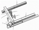
FIG. 1 is a perspective view of a fixture for an intelligent loading and unloading bin;
FIG. 2 is a front view of FIG. 1;
FIG. 3 is a schematic view of the internal structure of the X-axis electric sliding table;
FIG. 4 is a schematic view of an internal structure of the Z-axis electric sliding table;
fig. 5 is a schematic structural view of the clamping mechanism.
The attached drawings are as follows:
1. an X-axis electric sliding table; 11. a base; 12. an X-axis slide motor; 13. an X-axis sliding screw rod; 14. a slider; 15. a slide rail; 2. a Y-axis fixing frame; 3. a Z-axis electric sliding table; 31. a sliding table base; 32. a Z-axis lifting motor; 33. a Z-axis lifting screw rod; 34. a fixed block; 35. lifting the slide rail; 4. a clamping mechanism; 41. a bidirectional cylinder; 42. a left substrate; 43. a right substrate; 44. a motor shaft; 45. a left splint; 46. a right splint; 47. a groove; 5. a wire protective cover; 6. a part tray; 7. and (7) fixing the plate.
Detailed Description
For further disclosure and explanation of the technical solution of the present invention, the following description is made in conjunction with the accompanying drawings to provide a clear and complete explanation of the fixture for the intelligent feeding and discharging bin.
It should be noted that the terms "upper", "inner", "middle", "left", "right" and "one" used in the present specification are for convenience of description, and are not intended to limit the scope of the present invention, and the relative relationship between the terms and the corresponding elements may be changed or adjusted without substantial technical changes, and the scope of the present invention may be considered to be the scope of the present invention.
Referring to fig. 1 to 5, the present invention provides a fixture for an intelligent loading and unloading bin, comprising an X-axis electric sliding table 1, a Y-axis fixing frame 2, a Z-axis electric sliding table 3 and a clamping mechanism 4, wherein the X-axis electric sliding table 1 is provided with two X-axis electric sliding tables 1 arranged in parallel, each of the two X-axis electric sliding tables 1 comprises a base 11, an X-axis sliding motor 12, an X-axis sliding screw 13 and a slider 14, the X-axis sliding motor 12 is arranged at one end of the base 11, the X-axis sliding screw 13 is arranged in the base 11 and connected with the X-axis sliding motor 12, the base 11 is provided with a sliding rail 15, the slider 14 is arranged on the sliding rail 15 and connected with the X-axis sliding screw 13 by screw threads, the Y-axis fixing frame 2 is arranged on the slider 14, the Y-axis fixing frame 2 is provided with a fixing plate 7, the Z-axis electric sliding table 3 is arranged on the fixed plate 7, the clamping mechanism 4 is arranged on the Z-axis electric sliding table 3, and the X-axis sliding lead screw 13 can be driven to rotate through the work of the X-axis sliding motor 12, so that the sliding block 14 is driven to move back and forth in the sliding rail 15, and the Y-axis fixing frame 2 fixed on the sliding block 14 moves horizontally to drive the clamping mechanism 4 to move back and forth.
Specifically, the Z-axis electric sliding table 3 includes a sliding table base 31, a Z-axis lifting motor 32, a Z-axis lifting lead screw 33 and a fixed block 34, the Z-axis lifting motor 32 is disposed at the top of the sliding table base 31, the Z-axis lifting lead screw 33 is disposed inside the sliding table base 31 and connected to the Z-axis lifting motor 32, a lifting slide rail 35 is disposed on the sliding table base 31, the fixed block 34 is disposed in the lifting slide rail 35 and connected to the Z-axis lifting lead screw 33 by screw thread, the fixed block 34 is fixed on the fixed plate 7, the clamping mechanism 4 is fixed at the bottom of the sliding table base 31, the Z-axis lifting motor 32 drives the Z-axis lifting lead screw 33 to rotate and further act on the fixed block 34 by the action of the Z-axis lifting motor 32, and since the fixed block 34 is fixed on the fixed plate 7, the whole Z-axis electric sliding table 3 moves upwards or downwards relative to the fixed block 34 along the lifting, and then the clamping mechanism 4 is driven to adjust up and down.
Specifically, the clamping mechanism 4 includes a bidirectional cylinder 41, a left base plate 42 and a right base plate 43, the top of the bidirectional cylinder 41 is fixedly connected with the bottom of the sliding table base 31, the left base plate 42 and the right base plate 43 are respectively connected with a cylinder shaft 44 of the bidirectional cylinder 41, the left base plate 42 is fixedly connected with a left clamping plate 45, and the right base plate 43 is fixedly connected with a right clamping plate 46, it should be noted that, under the action of the bidirectional cylinder 41, the cylinder shaft 44 can be adjusted to extend or shorten, so that the left base plate 42 and the right base plate 43 extend or retract to two sides, and then the distance between the two base plates is adjusted, and further the distance between the left clamping plate 45 and the right clamping plate 46 is adjusted, so as to clamp or loosen the part tray 6.
Specifically, each of the left clamping plate 45 and the right clamping plate 46 is provided with a groove 47, and in this embodiment, the height of the groove 47 is equal to the height of the part tray 6, which is beneficial to further clamping the part tray 6 for carrying.
Specifically, the side of the X-axis electric sliding table 1 is further provided with a lead protection cover 5, and the lead protection cover 5 can be used for protecting a lead used for connecting a motor.
The utility model discloses a theory of operation does:
will the utility model discloses install the top at stereoscopic warehouse, control through backstage control box and software, when part tray 6 places in stereoscopic warehouse's dead ahead, the work of the electronic slip table of X axle 1, make Y axle mount 2 and the electronic slip table 3 of Z axle and the 4 translations of clamping mechanism, after the part tray 6 of dead ahead of alignment, the electronic slip table of Z axle 3 descends, clamping mechanism 4 presss from both sides tight part tray 6, the electronic slip table of Z axle 3 rises, the electronic slip table of X axle 1 moves back, then the electronic slip table of Z axle 3 descends, clamping mechanism 4 loosens part tray 6, put stereoscopic warehouse with part tray 6, with this circulation in the middle of with 6 stacks of part tray to the feed bin.
The utility model discloses an electronic slip table 1 of X axle carries out the horizontal migration of clamping mechanism 4, realizes reciprocating of clamping mechanism 4 through electronic slip table 3 of Z axle, will the utility model discloses install in stereoscopic warehouse's top, can deposit in the material clamping transport stereoscopic warehouse in the front just before stereoscopic warehouse, adopt the utility model discloses can avoid the manual work to carry the material to stereoscopic warehouse or avoid utilizing fork truck to carry the material to stereoscopic warehouse, have the characteristics that handling efficiency is high and the flexibility is high.
The present invention is not limited to the above embodiment, and if various modifications or changes of the present invention do not depart from the spirit and scope of the present invention, the present invention also includes such modifications and changes if such modifications and changes fall within the scope of the claims and the equivalent technology of the present invention.
Claims (5)
1. The utility model provides an anchor clamps that is used for feed bin about intelligence which characterized in that: including electronic slip table of X axle, Y axle mount, the electronic slip table of Z axle and clamping mechanism, the electronic slip table of X axle is provided with two, two the electronic slip table parallel arrangement of X axle, two the electronic slip table of X axle all includes base, X axle sliding motor, X axle slip lead screw and slider, X axle sliding motor set up in the one end of base, X axle slip lead screw set up in the base and with X axle sliding motor connects, be provided with the slide rail on the base, the slider set up in on the slide rail and with X axle slip lead screw threaded connection, Y axle mount install in on the slider, install the fixed plate on the Y axle mount, the electronic slip table of Z axle install in on the fixed plate, clamping mechanism install in on the electronic slip table of Z axle.
2. The clamp for the intelligent feeding and discharging bin according to claim 1, wherein: electronic slip table of Z axle includes slip table base, Z axle elevator motor, Z axle lift lead screw and fixed block, Z axle elevator motor set up in the top of slip table base, Z axle lift lead screw set up in inside the slip table base and with Z axle elevator motor connects, be provided with the lift slide rail on the slip table base, the fixed block set up in the lift slide rail and with Z axle lift lead screw threaded connection, the fixed block is fixed in on the fixed plate, the bottom of slip table base is fixed with clamping mechanism.
3. The clamp for the intelligent feeding and discharging bin according to claim 2, wherein: clamping mechanism includes two-way cylinder, left base plate and right base plate, the top of two-way cylinder with the bottom fixed connection of slip table base, left side base plate, right base plate are connected respectively the cylinder axle of two-way cylinder, fixedly connected with left splint on the left base plate, fixedly connected with right splint on the right base plate.
4. The clamp for the intelligent loading and unloading bin according to claim 3, wherein: and grooves are formed in the left clamping plate and the right clamping plate.
5. The clamp for the intelligent loading and unloading bin according to any one of claims 1 to 4, wherein: and a wire protection cover is also arranged on the side of the X-axis electric sliding table.
Priority Applications (1)
| Application Number | Priority Date | Filing Date | Title |
|---|---|---|---|
| CN201921249780.8U CN210417918U (en) | 2019-08-05 | 2019-08-05 | A anchor clamps that is used for feed bin about intelligence |
Applications Claiming Priority (1)
| Application Number | Priority Date | Filing Date | Title |
|---|---|---|---|
| CN201921249780.8U CN210417918U (en) | 2019-08-05 | 2019-08-05 | A anchor clamps that is used for feed bin about intelligence |
Publications (1)
| Publication Number | Publication Date |
|---|---|
| CN210417918U true CN210417918U (en) | 2020-04-28 |
Family
ID=70384498
Family Applications (1)
| Application Number | Title | Priority Date | Filing Date |
|---|---|---|---|
| CN201921249780.8U Active CN210417918U (en) | 2019-08-05 | 2019-08-05 | A anchor clamps that is used for feed bin about intelligence |
Country Status (1)
| Country | Link |
|---|---|
| CN (1) | CN210417918U (en) |
Cited By (1)
| Publication number | Priority date | Publication date | Assignee | Title |
|---|---|---|---|---|
| CN114516512A (en) * | 2022-03-28 | 2022-05-20 | 江苏西顿科技有限公司 | Warehouse for nuclear waste |
-
2019
- 2019-08-05 CN CN201921249780.8U patent/CN210417918U/en active Active
Cited By (1)
| Publication number | Priority date | Publication date | Assignee | Title |
|---|---|---|---|---|
| CN114516512A (en) * | 2022-03-28 | 2022-05-20 | 江苏西顿科技有限公司 | Warehouse for nuclear waste |
Similar Documents
| Publication | Publication Date | Title |
|---|---|---|
| CN110270973B (en) | Warehouse logistics robot and working method thereof, and automatic battery replacement method | |
| CN205855408U (en) | Self adaptation piling handgrip | |
| CN105364450A (en) | Full-automatic part sorting and conveying system | |
| CN210012199U (en) | Automatic stacker for warehouse goods shelves | |
| CN210417918U (en) | A anchor clamps that is used for feed bin about intelligence | |
| CN204823337U (en) | Last unloader of glass panels printing machine | |
| CN211337959U (en) | Tray carrying, lifting and tray distributing equipment | |
| CN109383974B (en) | Storage robot and control method thereof | |
| CN108455154B (en) | A kind of logistics goods storage system and method | |
| CN207943228U (en) | A kind of filling pipelining equipment | |
| CN210223981U (en) | Automatic feeding mechanism of semiconductor packaging all-in-one machine | |
| CN210824293U (en) | Linear parallel double-side lifting automatic hanging machine | |
| CN211002068U (en) | Packaging machinery hoisting device | |
| CN207087835U (en) | Solar panels performance detection on-gauge plate apparatus for temporary storage | |
| CN210504199U (en) | Feed bin about intelligence | |
| CN214732075U (en) | Electricity core balance device | |
| CN111924498A (en) | Universal large-capacity multilayer synchronous feeding mechanism | |
| CN113548354B (en) | Intelligent logistics storage system | |
| CN217755789U (en) | Feeding device for elevator | |
| CN215037473U (en) | Mechanical arm of stacking robot for logistics storage | |
| CN214491675U (en) | Automatic material taking mechanism of inductance element | |
| CN213327821U (en) | Substrate frame conveying device of vacuum coating machine | |
| CN220244412U (en) | Stereoscopic warehouse anti-falling device | |
| CN211194703U (en) | Automatic feeding device for producing battery case cover | |
| CN214878103U (en) | Stack feeding mechanism |
Legal Events
| Date | Code | Title | Description |
|---|---|---|---|
| GR01 | Patent grant | ||
| GR01 | Patent grant |