CN209889840U - Automatic feeding system used before combining coated automobile front windshield - Google Patents
Automatic feeding system used before combining coated automobile front windshield Download PDFInfo
- Publication number
- CN209889840U CN209889840U CN201920566045.3U CN201920566045U CN209889840U CN 209889840 U CN209889840 U CN 209889840U CN 201920566045 U CN201920566045 U CN 201920566045U CN 209889840 U CN209889840 U CN 209889840U
- Authority
- CN
- China
- Prior art keywords
- glass
- pair
- backrest
- belt conveyor
- synchronous belt
- Prior art date
- Legal status (The legal status is an assumption and is not a legal conclusion. Google has not performed a legal analysis and makes no representation as to the accuracy of the status listed.)
- Active
Links
Images


Abstract
A automatic system of going up line before being used for car front windshield to close piece, it includes glass placer (10), glass transfer device (20) and glass burst device, glass placer (10) are including fixing base (11), carousel (12), motor and glass rack (13), glass transfer device (20) are including the manipulator, frame (1), sliding plate (2), a pair of telescopic cylinder, a pair of rotatory die clamping cylinder and a pair of workbin (6) that connect that have feed inlet and discharge gate, glass burst device includes first hold-in range conveyer (31), second hold-in range conveyer (32), third hold-in range conveyer (33), longmen (34), second servo module (35), first lift cylinder (36), second lift cylinder (37), the utility model discloses the advantage is: the automatic loading device is mainly used for automatic loading before sheet combination, manual carrying is not needed, manpower is reduced, and production efficiency is improved.
Description
Technical Field
The utility model relates to a fender glass production line field before the car, concretely relates to be used for automatic online system before the piece is closed to fender glass before the coating film car.
Background
At present, the glass that keeps off glass before the piece closes the piece need be with placing of glass a slice before the piece closes the import department that closes piece equipment, because glass on the glass transports the frame is to putting (middle through a buckle, and this buckle only plays glass around distinguishing, and it is not very firm to block), then the manual work takes off the buckle, and a slice is carried glass to the import department that closes piece equipment, and this kind of manual mode is not conform to present production line demand.
Disclosure of Invention
The utility model aims to provide an automatic on-line system before the front windshield of a coated automobile closes the piece, aiming at the defects at present.
The utility model comprises a glass placing device, a glass transferring device and a glass slicing device,
the glass placing device comprises a fixed seat, a rotary table, a motor and a glass placing frame, the rotary table is movably arranged on the fixed seat through a rotary shaft, the motor is arranged on the fixed seat and is in transmission connection with the rotary shaft on the rotary table so as to drive the rotary table to rotate, the glass placing frame is arranged on the rotary table,
the glass transfer device comprises a mechanical arm, a frame, a sliding plate, a pair of telescopic cylinders, a pair of rotary clamping cylinders and a pair of material receiving boxes with a feed inlet and a discharge outlet, wherein a first vacuum glass sucker is fixedly arranged at one end of the frame, a first servo module is arranged on the frame, a connector connected with the power output end of the mechanical arm is arranged on the frame, the sliding plate is arranged on a sliding block of the first servo module, a second vacuum glass sucker is arranged at the power output end of the telescopic cylinders, a third vacuum glass sucker is arranged at the power output end of the rotary clamping cylinders, the pair of telescopic cylinders and the pair of rotary clamping cylinders are respectively arranged on the sliding plate through a bracket, and the pair of rotary clamping cylinders are positioned above the pair of telescopic cylinders, the pair of material receiving boxes are respectively arranged on the sliding plate, and the pair of telescopic cylinders and the pair of rotary clamping cylinders are positioned between the pair of material receiving boxes.
The glass slicing device comprises a first synchronous belt conveyor, a second synchronous belt conveyor, a third synchronous belt conveyor, a gantry, a second servo module, a first lifting cylinder and a second lifting cylinder,
the first synchronous belt conveyor, the second synchronous belt conveyor and the third synchronous belt conveyor are communicated in sequence,
the gantry is fixed on the ground, the second synchronous belt conveyor is positioned in the gantry,
the second servo module is detachably arranged in the frame of the second synchronous belt conveyor and the frame of the third synchronous belt conveyor, two stroke ends of the second servo module are respectively positioned in the second synchronous belt conveyor and the inlet of the third synchronous belt conveyor, a glass adsorption device is arranged on a power output shaft of the first lifting cylinder, the first lifting cylinder is arranged on a sliding block of the second servo module, a glass adsorption device is arranged on a power output shaft of the second lifting cylinder, the second lifting cylinder is arranged on the gantry through a support, and the glass adsorption device on the second lifting cylinder is positioned above the glass adsorption device on the first lifting cylinder.
The inlet ends of the turntable and the first synchronous belt conveyor are both in the stroke range of the manipulator.
The outlet of the material receiving box is provided with a pneumatic movable door to drive the movable door to open or close the outlet of the material receiving box through an air cylinder.
It also has an ultrasonic sensor for detecting the distance of the glass.
The glass adsorption device comprises at least four glass suckers and a sucker mounting seat, the at least four glass suckers are uniformly mounted on the sucker mounting seat, and the sucker mounting seat is mounted on a power output shaft of the first lifting cylinder through a connecting support.
The glass placing frame comprises an upper piece frame base, a backrest arranged in the middle of the upper piece frame base, a pressure rod, a first pressure rod guide rail, a second pressure rod guide rail, a fixed lock chain and a pressure rod accommodating part;
the backrest comprises two backrest vertical beams arranged on the upper sheet frame base, and a backrest upper cross beam, a backrest middle cross beam and a backrest lower cross beam which are arranged between the two backrest vertical beams;
the first pressure bar guide rail comprises a pair of first rectangular pipes, a first connecting plate and a second connecting plate, wherein the first connecting plate and the second connecting plate are fixedly connected with the upper parts and the lower parts of the pair of first rectangular pipes respectively;
the second pressure bar guide rail comprises a pair of second rectangular pipes and a third connecting plate fixedly connected with the lower parts of the pair of second rectangular pipes, the upper parts of the pair of second rectangular pipes are fixedly connected with the second connecting plate, the pair of first rectangular pipes and the pair of second rectangular pipes are positioned on two sides of the backrest, and a plurality of pairs of first positioning holes are formed in the first rectangular pipes and the second rectangular pipes;
the first rectangular pipe and the second rectangular pipe are both sleeved with a guide rail sliding sleeve, the guide rail sliding sleeve is provided with a pair of second positioning holes matched with the positioning holes, a bolt penetrates through the pair of first positioning holes and the pair of second positioning holes to fix the guide rail sliding sleeve, the side wall of the guide rail sliding sleeve is provided with a U-shaped block, and a cross rod is arranged inside the U-shaped block;
one end of the pressure lever is provided with a first fixed hook, the other end of the pressure lever is provided with a U-shaped clamping groove with an upward opening, the U-shaped clamping groove is matched with the cross rod, the groove width of the U-shaped clamping groove is the same as the diameter of the cross rod, so that the pressure lever is clamped on the cross rod of the U-shaped block, two second fixed hooks are arranged on the upper sheet frame base in an upward direction, and the fixed lock chain is hung on the first fixed hook and the second fixed hook; the stop block is provided with a butterfly bolt for fixing the stop block and the compression bar;
the pressure bar containing part comprises two first safety stop blocks and a plurality of L-shaped pressure bar supporting plates, wherein the two first safety stop blocks are arranged on one side of the upper sheet frame base and are respectively positioned at two ends of the upper sheet frame base, and the L-shaped pressure bar supporting plates are arranged between the two first safety stop blocks.
Two pairs of silica gel strips are arranged on the upper film frame base, and the two pairs of silica gel strips are symmetrically arranged on two sides of the upper film frame backrest.
And a pressure bar limiting block is also arranged in the middle between the two first safety stop blocks on one side of the upper sheet frame base.
The third connecting plate and the second connecting plate are respectively abutted against the lower backrest cross beam and the middle backrest cross beam, the third connecting plate is located below the lower backrest cross beam, and the second connecting plate is located above the middle backrest cross beam.
And the upper part of the vertical beam of the backrest is provided with a chain hook and a second safety stop block.
The utility model has the advantages that: the automatic loading device is mainly used for automatic loading before sheet combination, manual carrying is not needed, manpower is reduced, and production efficiency is improved.
Drawings
Fig. 1 is a schematic structural diagram of the present invention.
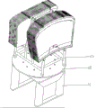
Fig. 2 is a schematic view of the glass placement device.
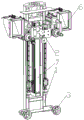
FIG. 3 is a schematic view of the glass transfer device.
FIG. 4 is a schematic view showing a mounting position of the second vacuum glass chuck.
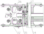
FIG. 5 is a schematic view of a second servo module mounting position.
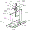
FIG. 6 is a schematic structural view of the glass placement frame;
FIG. 7 is a schematic side view of the structure of FIG. 6;
FIG. 8 is a schematic structural view of a guide rail sliding sleeve;
FIG. 9 is a schematic structural view of the pressing rod;
FIG. 10 is a schematic view of a stop block;
FIG. 11 is a schematic structural view of a second fixing hook;
FIG. 12 is a schematic structural view of a first safety block and an L-shaped pressure bar support plate;
FIG. 13 is a schematic view of the connection relationship at the second connecting plate;
FIG. 14 is a schematic view of the chain shackle and second safety stop.
Detailed Description
In order to make the objects, technical solutions and advantages of the embodiments of the present invention clearer, the technical solutions in the embodiments of the present invention will be clearly and completely described below with reference to the drawings in the embodiments of the present invention, and it is obvious that the described embodiments are some, but not all, embodiments of the present invention. The components of embodiments of the present invention generally described and illustrated in the figures herein may be arranged and designed in a wide variety of different configurations.
Thus, the following detailed description of the embodiments of the present invention, presented in the figures, is not intended to limit the scope of the invention, as claimed, but is merely representative of selected embodiments of the invention. All other embodiments, which can be derived by a person skilled in the art from the embodiments given herein without making any creative effort, shall fall within the protection scope of the present invention.
It should be noted that: like reference numbers and letters refer to like items in the following figures, and thus, once an item is defined in one figure, it need not be further defined and explained in subsequent figures.
In the description of the embodiments of the present invention, it should be noted that, if the terms "upper", "lower", "inside", "outside", etc. are used for indicating the orientations or positional relationships based on the orientations or positional relationships shown in the drawings or the orientations or positional relationships that the products of the present invention usually place when using, the present invention is only used for convenience of description and simplification of the description, but does not indicate or imply that the devices or elements indicated must have specific orientations, be constructed in specific orientations, and operate, and thus, the present invention should not be construed as being limited. Furthermore, the appearances of the terms "first," "second," and the like in the description of the present invention are only used for distinguishing between the descriptions and are not intended to indicate or imply relative importance.
In the description of the embodiments of the present invention, it should be further noted that unless otherwise explicitly stated or limited, the terms "disposed" and "connected" should be interpreted broadly, and may be, for example, fixedly connected, detachably connected, or integrally connected; can be mechanically or electrically connected; they may be connected directly or indirectly through intervening media, or they may be interconnected between two elements. The specific meanings of the above terms in the present invention can be understood in specific cases to those skilled in the art.
As shown in the figure, the utility model comprises a glass placing device 10, a glass transferring device 20 and a glass slicing device,
the glass placing device 10 comprises a fixed seat 11, a rotary table 12, a motor and a glass placing frame 13, wherein the rotary table 12 is movably arranged on the fixed seat 11 through a rotary shaft, the motor is arranged on the fixed seat 11 and is in transmission connection with the rotary shaft on the rotary table 12 so as to drive the rotary table 12 to rotate, the glass placing frame 13 is placed on the rotary table 12,
the glass transfer device 20 comprises a manipulator, a frame 1, a sliding plate 2, a pair of telescopic cylinders, a pair of rotary clamping cylinders and a pair of material receiving boxes 6 with a feeding port and a discharging port, wherein a first vacuum glass sucker 3 is fixedly arranged at one end of the frame 1, a first servo module 7 is arranged on the frame 1, a connector connected with a mechanical manual power output end is arranged on the frame 1, the sliding plate 2 is arranged on a sliding block of the first servo module 7, a second vacuum glass sucker 4 is arranged at the power output end of the telescopic cylinders, a third vacuum glass sucker 5 is arranged at the power output end of the rotary clamping cylinders, the pair of telescopic cylinders and the pair of rotary clamping cylinders are respectively arranged on the sliding plate 2 through a bracket, and the pair of rotary clamping cylinders are positioned above the pair of telescopic cylinders, the pair of material receiving boxes 6 are respectively arranged on the sliding plate 2, and the pair of telescopic cylinders and the pair of rotary clamping cylinders are positioned between the pair of material receiving boxes 6.
The glass slicing device comprises a first synchronous belt conveyor 31, a second synchronous belt conveyor 32, a third synchronous belt conveyor 33, a gantry 34, a second servo module 35, a first lifting cylinder 36 and a second lifting cylinder 37,
the first synchronous belt conveyor 31, the second synchronous belt conveyor 32 and the third synchronous belt conveyor 33 are communicated in sequence,
the gantry 34 is fixed to the ground, and the second timing belt conveyor 32 is located within the gantry 34,
the second servo module 35 is detachably mounted in the frames of the second synchronous belt conveyor 32 and the third synchronous belt conveyor 33, two stroke ends of the second servo module 35 are respectively located in the second synchronous belt conveyor 32 and at the inlet of the third synchronous belt conveyor 33, a glass adsorption device is arranged on a power output shaft of the first lifting cylinder 36, the first lifting cylinder 36 is mounted on a sliding block of the second servo module 35, a glass adsorption device is arranged on a power output shaft of the second lifting cylinder 37, the second lifting cylinder 37 is mounted on the gantry 34 through a support, and the glass adsorption device on the second lifting cylinder 37 is located above the glass adsorption device on the first lifting cylinder 36.
The inlet end of the turntable 12 and its first synchronous belt conveyor 31 are within the range of travel of the robot.
The outlet of the material receiving box 6 is provided with a pneumatic movable door to drive the movable door to open or close the outlet of the material receiving box 6 through an air cylinder.
It also has an ultrasonic sensor for detecting the distance of the glass.
The glass adsorption device comprises at least four glass suckers and a sucker mounting seat, the at least four glass suckers are uniformly mounted on the sucker mounting seat, and the sucker mounting seat is mounted on a power output shaft of the first lifting cylinder 36 through a connecting support.
The glass placing frame 13 comprises an upper sheet frame base 101, a backrest 102 arranged in the middle of the upper sheet frame base 101, a pressure lever 103, a first pressure lever guide rail 104, a second pressure lever guide rail 105, a fixed chain 106 and a pressure lever accommodating part;
the backrest 102 comprises two backrest vertical beams 1021 arranged on the upper sheet rack base 101, and an upper backrest cross beam 1022, a middle backrest cross beam 1023 and a lower backrest cross beam 1024 arranged between the two backrest vertical beams 1021;
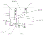
the first strut guide rail 104 comprises a pair of first rectangular tubes 1041, a first connecting plate 1042 and a second connecting plate 1043 fixedly connected with the upper part and the lower part of the pair of first rectangular tubes 1041 respectively, the first connecting plate 1042 is positioned above the backrest upper cross beam 1022, the first connecting plate 1042 and the backrest upper cross beam 1022 are connected through an upper support beam 1044, the second connecting plate 1043 is positioned between the backrest upper cross beam 1022 and the backrest middle cross beam 1023, and the second connecting plate 1043 and the backrest upper cross beam 1022 are connected through a lower support beam 1045;
the second pressure bar guide rail 105 comprises a pair of second rectangular pipes 1051 and a third connecting plate 1052 fixedly connected with the lower parts of the pair of second rectangular pipes 1051, the upper parts of the pair of second rectangular pipes 1051 are fixedly connected with the second connecting plate 1043, the pair of first rectangular pipes 1041 and the pair of second rectangular pipes 1051 are positioned at two sides of the backrest 102, and a plurality of pairs of first positioning holes 107 are arranged on the first rectangular pipes 1041 and the second rectangular pipes 1051;
a guide rail sliding sleeve 108 is sleeved on each of the first rectangular tube 1041 and the second rectangular tube 1051, a pair of second positioning holes 109 matched with the positioning holes 107 are formed in the guide rail sliding sleeve 108, a bolt 1030 penetrates through the pair of first positioning holes 107 and the pair of second positioning holes 109 to fix the guide rail sliding sleeve 108, a U-shaped block 1010 is arranged on the side wall of the guide rail sliding sleeve 108, and a cross rod 1011 is arranged inside the U-shaped block 1010;
one end of the pressure lever 103 is provided with a first fixed hook 1012, the other end of the pressure lever 103 is provided with a U-shaped clamping groove 1013 with an upward opening and matched with the cross rod 1011, the width of the U-shaped clamping groove 1013 is the same as the diameter of the cross rod 1011, so that the pressure lever 103 is clamped on the cross rod 1011 of the U-shaped block 1010, the upper rack base 101 is provided with two second fixed hooks 1017 upward, and the fixed lock chain 106 is hung on the first fixed hook 1012 and the second fixed hook 1017; a stop block 1014 is slidably sleeved on the compression bar 103, and a butterfly bolt 1025 for fixing the stop block 1014 and the compression bar 103 is arranged on the stop block 1014;
the pressure bar receiving portion comprises two first safety stops 1015 arranged on one side of the upper rack base 101 and respectively positioned at two ends of the upper rack base, and a plurality of L-shaped pressure bar supporting plates 1016 arranged between the two first safety stops 1015.
Two pairs of silica gel strips 1018 are arranged on the upper rack base 101, and the two pairs of silica gel strips 1018 are symmetrically arranged on two sides of the upper rack backrest 102.
And a pressure bar limiting block is further arranged in the middle between the two first safety stop blocks 1015 on one side of the upper rack base 101.
The third connecting plate 1052 and the second connecting plate 1043 respectively abut against the lower backrest cross beam 1024 and the middle backrest cross beam 1023, the third connecting plate 1052 is located below the lower backrest cross beam 1024, and the second connecting plate 1043 is located above the middle backrest cross beam 1023.
The upper part of the vertical backrest beam 1021 is provided with a chain hook 1019 and a second safety stop 1020.
Glass rack theory of operation: an operator firstly selects to fix the pressure lever 103 on the first pressure lever guide rail 104 or the second pressure lever guide rail 105 according to the size of the automobile skylight or the front windshield (the U-shaped clamping groove 1013 of the pressure lever 103 is upwards put into the U-shaped block 1010, and the cross rod 1011 is wrapped in the U-shaped clamping groove 1013, so that the pressure lever 103 is clamped on the cross rod 1011 of the U-shaped block 1010), then, the glass is placed on the silica gel strip 1018 of the upper rack base 101, one side of the glass is leaned against the first rectangular tube 1041 or the second rectangular tube 1051, the position of the guide rail sliding sleeve 108 on the first rectangular tube 1041 or the second rectangular tube 1051 is adjusted, the pressure lever 103 is enabled to be propped against the top of the glass, the position of the stop block 1014 on the press rod 103 is adjusted by sliding according to the space occupied by the glass after being put in, and the fixed chain 106 can be hung on the first fixed hook 1012 and the second fixed hook 1017 after the glass is full, and the glass is sucked by the waiting manipulator.
The working mode is as follows: when the device is used, the manipulator drives the device to move to a glass placing frame 13 (when one side of glass is used up, a motor drives a rotary table 12 to rotate to grab the glass on the other side), the glass is in an inclined state at the moment, two pieces of glass are clamped together (only a limiting effect is achieved, and two pieces of glass cannot be clamped) through a buckle, after the manipulator reaches a specified position, the second vacuum glass sucker 4 firstly contacts with the glass and starts to suck the glass after contacting with the glass, after the suction, the telescopic cylinder returns to the original position, the glass is erected and contacts with the first vacuum glass sucker 3 while being erected, after the first vacuum glass sucker 3 sucks the glass or when the glass is erected, the third vacuum glass sucker 5 is pushed against the other side of the other piece of glass after the pair of rotary clamping cylinders rotates and sucks the glass, the mechanical arm moves backwards to take out the glass, after the step is finished, the mechanical arm drives the frame 1 and the glass to rotate to a lying state, the glass is slowly in an inclined state while rotating, the buckle clamped on the glass falls into the material receiving box 6, finally, the mechanical arm places the two pieces of glass with the buckle removed at the inlet of the first synchronous belt conveyor 31, the first vacuum glass sucker 3, the second vacuum glass sucker 4 and the third vacuum glass sucker 5 deflate, the first synchronous belt conveyor 31 drives the two pieces of glass to enter the second synchronous belt conveyor 32, at the moment, the second lifting cylinder 37 drives the glass adsorption device to descend and adsorb on the glass above the two pieces of glass for adsorption, the second lifting cylinder 37 ascends after adsorption, at the moment, the first lifting cylinder 36 ascends to drive the lower layer of glass to be separated from the second synchronous belt conveyor 32 and drive the glass on the first lifting cylinder 36 to move to the third synchronous belt conveyor 33 through the second servo module 35, after the first lifting cylinder 36 descends and places glass on the third synchronous belt conveyor 33, the first lifting cylinder 36 returns, after returning, the second lifting cylinder 37 descends and places glass on the glass adsorption device of the first lifting cylinder 36, the glass adsorption device on the second lifting cylinder 37 deflates, the glass adsorption device of the first lifting cylinder 36 inhales, after adsorption, the glass is conveyed to the third synchronous belt conveyor 33 and returns, and the glass on the third synchronous belt conveyor 33 is ready to enter the sheet combining machine for combining sheets.
After the buckle gets into and connects workbin 6, through reaching the assigned position after, open the dodge gate in exit, make the buckle fall into the collection box.
The first servo module 7 mainly serves to adjust the position of the slide plate 2 to accommodate various sizes of glass.
The burst adopts the syllogic transmission, uses the servo module in lower part as moving the shuttle and moves glass and move and carry, mainly because second hold-in range conveyer length is very big, in order to accelerate the production beat, need carry out fast transmission through this mode, and this mode transmission efficiency is high, excellent in use effect.
Claims (9)
1. The automatic on-line system used before the laminating of the coated automobile front windshield is characterized by comprising a glass placing device (10), a glass transferring device (20) and a glass slicing device,
the glass placing device (10) comprises a fixed seat (11), a rotary table (12), a motor and a glass placing frame (13), wherein the rotary table (12) is movably arranged on the fixed seat (11) through a rotary shaft, the motor is arranged on the fixed seat (11) and is in transmission connection with the rotary shaft on the rotary table (12) so as to drive the rotary table (12) to rotate, the glass placing frame (13) is placed on the rotary table (12),
the glass transfer device (20) comprises a manipulator, a rack (1), a sliding plate (2), a pair of telescopic cylinders, a pair of rotary clamping cylinders and a pair of material receiving boxes (6) with a feeding port and a discharging port, wherein one end of the rack (1) is fixedly provided with a first vacuum glass sucker (3), the rack (1) is provided with a first servo module (7), the rack (1) is provided with a connector connected with a mechanical manual power output end, the sliding plate (2) is arranged on a sliding block of the first servo module (7), the power output end of the telescopic cylinders is provided with a second vacuum glass sucker (4), the power output end of the rotary clamping cylinders is provided with a third vacuum glass sucker (5), the pair of telescopic cylinders and the pair of rotary clamping cylinders are respectively arranged on the sliding plate (2) through supports, and the pair of rotary clamping cylinders are positioned above the pair of telescopic cylinders, a pair of material receiving boxes (6) are respectively arranged on the sliding plate (2), and a pair of telescopic cylinders and a pair of rotary clamping cylinders are positioned between the pair of material receiving boxes (6),
the glass slicing device comprises a first synchronous belt conveyor (31), a second synchronous belt conveyor (32), a third synchronous belt conveyor (33), a gantry (34), a second servo module (35), a first lifting cylinder (36) and a second lifting cylinder (37),
the first synchronous belt conveyor (31), the second synchronous belt conveyor (32) and the third synchronous belt conveyor (33) are communicated in sequence,
the gantry (34) is fixed on the ground, the second synchronous belt conveyor (32) is positioned in the gantry (34),
the second servo module (35) is detachably arranged in the machine frame of the second synchronous belt conveyor (32) and the third synchronous belt conveyor (33), two stroke ends of the second servo module (35) are respectively positioned at the inlet of the second synchronous belt conveyor (32) and the inlet of the third synchronous belt conveyor (33), a glass adsorption device is arranged on a power output shaft of the first lifting cylinder (36), the first lifting cylinder (36) is arranged on a slide block of the second servo module (35), a glass adsorption device is arranged on a power output shaft of the second lifting cylinder (37), the second lifting cylinder (37) is arranged on the gantry (34) through a bracket, and the glass adsorption device on the second lifting cylinder (37) is positioned above the glass adsorption device on the first lifting cylinder (36),
the inlet ends of the turntable (12) and the first synchronous belt conveyor (31) are all in the stroke range of the manipulator.
2. The automatic front windshield sheet-closing on-line system for the coated automobile according to claim 1, characterized in that a pneumatic movable door is arranged at the outlet of the material receiving box (6) to open or close the outlet of the material receiving box (6) by driving the movable door through a cylinder.
3. The system of claim 1, further comprising an ultrasonic sensor for detecting the distance between the glass sheets.
4. The automatic on-line system before closing for coating automobile front windshield according to claim 1, wherein the glass adsorption device comprises at least four glass suckers and a sucker mounting seat, the at least four glass suckers are uniformly arranged on the sucker mounting seat, and the sucker mounting seat is arranged on a power output shaft of the first lifting cylinder (36) through a connecting bracket.
5. The automatic front windshield sheet-closing wire-feeding system for the coated automobile front windshield sheet-closing device according to claim 1, wherein the glass placing frame (13) comprises an upper frame base (101), a backrest (102) arranged in the middle of the upper frame base (101), a pressure rod (103), a first pressure rod guide rail (104), a second pressure rod guide rail (105), a fixed lock chain (106) and a pressure rod accommodating part;
the backrest (102) comprises two backrest vertical beams (1021) arranged on the upper sheet rack base (101), and a backrest upper cross beam (1022), a backrest middle cross beam (1023) and a backrest lower cross beam (1024) which are arranged between the two backrest vertical beams (1021);
the first compression bar guide rail (104) comprises a pair of first rectangular tubes (1041), a first connecting plate (1042) and a second connecting plate (1043) which are fixedly connected with the upper portion and the lower portion of the pair of first rectangular tubes (1041) respectively, the first connecting plate (1042) is located above the backrest upper cross beam (1022), the first connecting plate (1042) is connected with the backrest upper cross beam (1022) through an upper supporting beam (1044), the second connecting plate (1043) is located between the backrest upper cross beam (1022) and the backrest middle cross beam (1023), and the second connecting plate (1043) is connected with the backrest upper cross beam (1022) through a lower supporting beam (1045);
the second pressure bar guide rail (105) comprises a pair of second rectangular pipes (1051) and a third connecting plate (1052) fixedly connected with the lower parts of the second rectangular pipes (1051), the upper parts of the second rectangular pipes (1051) are fixedly connected with the second connecting plate (1043), the first rectangular pipes (1041) and the second rectangular pipes (1051) are located on two sides of the backrest (102), and a plurality of pairs of first positioning holes (107) are formed in the first rectangular pipes (1041) and the second rectangular pipes (1051);
the guide rail sliding sleeve (108) is sleeved on each of the first rectangular tube (1041) and the second rectangular tube (1051), a pair of second positioning holes (109) matched with the positioning holes (107) are formed in the guide rail sliding sleeve (108), a bolt (1030) penetrates through the pair of first positioning holes (107) and the pair of second positioning holes (109) to fix the guide rail sliding sleeve (108), a U-shaped block (1010) is arranged on the side wall of the guide rail sliding sleeve (108), and a cross rod (1011) is arranged inside the U-shaped block (1010);
one end of the pressure lever (103) is provided with a first fixed hook (1012), the other end of the pressure lever is provided with a U-shaped clamping groove (1013) with an upward opening, the U-shaped clamping groove (1013) is matched with the cross rod (1011), the width of the U-shaped clamping groove (1013) is the same as the diameter of the cross rod (1011), so that the pressure lever (103) is clamped on the cross rod (1011) of the U-shaped block (1010), the upper rack base (101) is provided with two second fixed hooks (1017) upwards, and the fixed lock chain (106) is hung on the first fixed hook (1012) and the second fixed hook (1017); a stop block (1014) is slidably sleeved on the pressure lever (103), and a butterfly bolt (1025) for fixing the stop block (1014) and the pressure lever (103) is arranged on the stop block (1014);
the pressure bar containing part comprises two first safety stop blocks (1015) which are arranged on one side of the upper sheet frame base (101) and are respectively positioned at two ends of the upper sheet frame base, and a plurality of L-shaped pressure bar supporting plates (1016) which are arranged between the two first safety stop blocks (1015).
6. The automatic front windshield sheet-combining feeding system for the coated automobile front windshield sheet according to claim 5, wherein two pairs of silica gel strips (1018) are arranged on the upper sheet frame base (101), and the two pairs of silica gel strips (1018) are symmetrically arranged on two sides of the upper sheet frame backrest (102).
7. The automatic front windshield sheet-closing feeding system for the coated automobile according to claim 5, wherein a pressure rod limiting block is further arranged in the middle between the two first safety stoppers (1015) on one side of the upper sheet frame base (101).
8. The system of claim 5, wherein the third connecting plate (1052) and the second connecting plate (1043) respectively abut against the lower back cross member (1024) and the middle back cross member (1023), the third connecting plate (1052) is located below the lower back cross member (1024) and the second connecting plate (1043) is located above the middle back cross member (1023).
9. The automatic front windshield sheet-combining threading system for the coated automobile according to claim 5, wherein the upper part of the vertical backrest beam (1021) is provided with a chain hook (1019) and a second safety stop (1020).
Priority Applications (1)
| Application Number | Priority Date | Filing Date | Title |
|---|---|---|---|
| CN201920566045.3U CN209889840U (en) | 2019-04-24 | 2019-04-24 | Automatic feeding system used before combining coated automobile front windshield |
Applications Claiming Priority (1)
| Application Number | Priority Date | Filing Date | Title |
|---|---|---|---|
| CN201920566045.3U CN209889840U (en) | 2019-04-24 | 2019-04-24 | Automatic feeding system used before combining coated automobile front windshield |
Publications (1)
| Publication Number | Publication Date |
|---|---|
| CN209889840U true CN209889840U (en) | 2020-01-03 |
Family
ID=69019553
Family Applications (1)
| Application Number | Title | Priority Date | Filing Date |
|---|---|---|---|
| CN201920566045.3U Active CN209889840U (en) | 2019-04-24 | 2019-04-24 | Automatic feeding system used before combining coated automobile front windshield |
Country Status (1)
| Country | Link |
|---|---|
| CN (1) | CN209889840U (en) |
Cited By (1)
| Publication number | Priority date | Publication date | Assignee | Title |
|---|---|---|---|---|
| CN111056312A (en) * | 2019-04-24 | 2020-04-24 | 福耀玻璃(湖北)有限公司 | Automatic wire feeding system used before automobile front windshield combining |
-
2019
- 2019-04-24 CN CN201920566045.3U patent/CN209889840U/en active Active
Cited By (1)
| Publication number | Priority date | Publication date | Assignee | Title |
|---|---|---|---|---|
| CN111056312A (en) * | 2019-04-24 | 2020-04-24 | 福耀玻璃(湖北)有限公司 | Automatic wire feeding system used before automobile front windshield combining |
Similar Documents
| Publication | Publication Date | Title |
|---|---|---|
| CN209698378U (en) | Battery of mobile phone automatic assembling | |
| CN106514249B (en) | A kind of smoke alarm assembly line | |
| CN111048845B (en) | Storage battery film coating mechanism | |
| CN209947955U (en) | Full-automatic rubberizing production line of battery | |
| CN108340157B (en) | Camera assembly production line | |
| CN111056312A (en) | Automatic wire feeding system used before automobile front windshield combining | |
| CN209889840U (en) | Automatic feeding system used before combining coated automobile front windshield | |
| CN110712779B (en) | Full-automatic packaging equipment suitable for LED electronic display screen | |
| CN210781957U (en) | Connector assembling machine | |
| CN212732782U (en) | A rubber coating system for on liquid crystal glazing production line | |
| CN209870923U (en) | Automatic change aircraft box folder | |
| CN114670431A (en) | Using method of automatic adhesive tape sticking equipment | |
| CN209870922U (en) | Automatic change automatic packing plant of aircraft box folder | |
| CN210758064U (en) | Automatic leading-in device | |
| CN209889839U (en) | Automatic on-line system before car suppression front windshield packing | |
| CN219839132U (en) | Automatic feeding and discharging equipment based on AGV | |
| CN215205550U (en) | A envelope pile up neatly device for light guide plate | |
| CN209835022U (en) | Glass transfer device for automatic on-line before combining automobile front windshield | |
| CN220497578U (en) | Automatic frame unloading conveying mechanism that inserts of product | |
| CN218641832U (en) | Supplementary photovoltaic module outward appearance detects tilting mechanism | |
| CN219448396U (en) | Long and short side rubberizing equipment in display screen processing | |
| CN220153833U (en) | Relay vacuum degree detector | |
| CN216335207U (en) | Last unloading subassembly of battery piece thickness check out test set | |
| CN218224142U (en) | Double-rail automatic bending machine | |
| CN220431334U (en) | Multi-position automatic feeding and carrying equipment for ceramic detection jig |
Legal Events
| Date | Code | Title | Description |
|---|---|---|---|
| GR01 | Patent grant | ||
| GR01 | Patent grant |